HAL Id: hal-01719979
https://hal.archives-ouvertes.fr/hal-01719979
Submitted on 28 Feb 2018
HAL is a multi-disciplinary open access
archive for the deposit and dissemination of
sci-entific research documents, whether they are
pub-lished or not. The documents may come from
teaching and research institutions in France or
abroad, or from public or private research centers.
L’archive ouverte pluridisciplinaire HAL, est
destinée au dépôt et à la diffusion de documents
scientifiques de niveau recherche, publiés ou non,
émanant des établissements d’enseignement et de
recherche français ou étrangers, des laboratoires
publics ou privés.
A new inductorless DC-DC piezoelectric flyback
converter
Benjamin Pollet, Ghislain Despesse, François Costa
To cite this version:
Benjamin Pollet, Ghislain Despesse, François Costa. A new inductorless DC-DC piezoelectric flyback
converter. ICIT IEEE 2018, Feb 2018, Lyon, France. �hal-01719979�
A new inductorless DC-DC piezoelectric flyback
converter
Benjamin POLLET CEA LETI Grenoble, France SATIE, ENS Paris-Saclay
Cachan, France [email protected]
François Costa SATIE, ENS Paris-Saclay
Cachan, France Université Paris-Est Créteil,
ESPE Saint-Denis, France franç[email protected]
Ghislain Despesse CEA LETI Grenoble, France [email protected]
Abstract—This paper introduces a new kind of piezoelectric
DC-DC converter. A ceramic is used as an energy storage element to replace the traditional inductance. Once resonating, the system describes a cycle at each resonance period taking energy to the source, storing it temporarily and transmitting it to the load with soft switching. A resonator suitable for the converter is presented and characterized with an electrical equivalent model. A simulation representing the whole system, gives very attracting results with very high efficiency for different output powers. The converter was tested and fully validated by experimental works. An efficiency of 85 percent was reached for a 10-20 volts step up converter with an output power of 500 milliwatts.
Keywords—DC/DC-conversion, piezoelectric materials, inductor-less converters, mechanical storage.
I. INTRODUCTION
DC/DC converters market has kept growing during the past decades representing now billions of dollars [1]. The large diversity of their application fields (aviation, computer science, energy harvesting...) implies specific constraints and specific technological solutions. In this context, using piezoelectric materials for power conversion can be very relevant for some applications, one of them being low power with high voltage gain converters [2]. Therefore numerous converters with piezoelectric transformers (PT) were developed [3-5]. However, an inductance is necessary to obtain a high efficiency in DC/DC converters with PT [6]. In this paper, a new inductor-less boost converter with one single piezoelectric element (no coupled piezoelectric like in PT) is presented. The material works at its resonant frequency and behaves as an energy storage element like an inductance does in classical power electronics circuits. Therefore the storage is mechanic and not magnetic. A similar mechanics-based converter, using a variable capacitor instead of a piezoelectric resonator was proposed but the piezoelectric solution is advantageous in term of quality factor, power density and ease of implementation [7]. Very few piezoelectric converters without PT are described in the state of the art. The few ones presented operate like an improved switched capacitors converter, limiting the voltage gain unless to use a large number of piezoelectric and making
the efficiency very sensitive to load variations [8_9]. The presented converter is inductor-less, and has a high efficiency with a large set of possible voltage gain values.
II. STEP-UP CONVERTER DESCRIPTION
A. Topology presentation
The DC/DC converter is represented in Fig.1. In steady state, the transducer is resonating at its resonance frequency. Therefore, if all the switches are off, there is no charge transfer to the material and the piezoelectric voltage (Vp) variation is
sinusoidal. If one switch is turned on, Vp is constant and a
sinusoidal current transfer occurs. The converter principle is to alternate, constant voltage and constant charge phases to take energy from the source, storing it and giving it back to the load. This constitutes a cycle with an indirect energy transfer as in a popular magnetics-based flyback converter. At each cycle, the amount of energy get from the source must be the same as the one distributed to the load added to the lost one in order to maintain the resonance amplitude.
B. Cycle description in steady state
The whole 6-phases cycle is represented in Fig.2 for a 10-20 Volt converter. The origin of time is chosen when Vp is
equal to Vout and the resonator internal current is null. At this
time, all the switches are off and the voltage drops until reaching Vin (phase1).
When Vp is equal to Vin, kin is turned on to connect the
piezoelectric material to the input voltage with zero voltage switching mode (ZVS) in order to avoid switching losses.
Vin
kin kout
Vout k
3 Vp
Fig.2. Steady-state piezoelectric waveforms.
During this phase, Vp is equal to Vin and the resonator takes
energy from the source (phase2).
Then kin is turned off and Vp drops until reaching zero volt
when the piezoelectric deformation is maximum and the intern current generated by the vibration is zero (phase3).
When Vp is equal to zero volt, k3 is turned on to have a
ZVS commutation and the voltage remains zero (phase 4). k3 is turned off and Vp increases until reaching Vout.
(phase5).
When Vp is equal to Vout, kout is turned on with no
switching losses (ZVS mode). In this phase, the material is restituting energy to the load. This constant voltage phase lasts until the transfer current reaches zero (phase6). Then a new cycle begins.
C. Strategy of control
The control ensures ZVS operations and regulates the output voltage. Since the switches must be driven within a resonant period, it has to be faster than a classical frequency control. Fig.3 illustrates the control strategy. A diode is used for kout, therefore there is no need to control it. For turning on
kin, a comparator detects when Vp crosses Vin and orders to turn
it on for ZVS working. kin is switched off at a time that
permits Vp to reach zero volt exactly at half of the period (t3).
To achieve this, an internal regulation loop on t2 is necessary,
based on the time’s error on the zero voltage crossing around t3
in the previous cycle. The transition time t4, where k3 is
opened, is the one and only degree of freedom: the higher it is, the higher the output power is. This t4 parameter is used to
regulate the output voltage thanks to a proportional integral (PI) corrector. This regulation loop enables to reach the good piezoelectric displacement amplitude compared to the power demand: the internal current amplitude of the piezoelectric and then the current level exchanged with the external parts is proportional to that amplitude. Once the power demand is stabilized, the closed loop ensures energy balance between the input energy, output energy and lost energy in order to maintain the piezoelectric movement amplitude constant (steady state).
Fig.3. Strategy of control.
III. CHOICE OF THE PIEZOELECTRIC RESONATOR
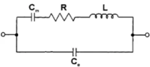
The piezoelectric transducer must have specific properties to fit the application. To optimize the efficiency and the maximal output power, the material must have both a high electro/mechanical coupling and a high quality factor. To evaluate the characteristics of the material, an electrical equivalent model of the piezoelectric resonator is used. This model is shown in Fig.4. Each element of the model has a physical meaning. C0 represents the real electric capacitance of
the material, and the other branch corresponds to the mechanical part. R expresses the mechanical losses inside the material. L is representing the mass and Cm the stiffness of the
material. The dielectric losses can be represented as well by a parallel resistance across the material but are neglected as they are very low. At resonance, the equivalent impedance of the mechanical part is just R and the current goes through the second branch. With this model (only relevant when close to the resonant frequency), it is simple to determine the equivalent parameters from an impedance analysis [10]. The knowledge of the equivalent elements gives the quality factor Q and the coupling factor kp thanks to (1) and (2).
A disc shaped PZT ceramic (Fuji Ceramic C-213) having a very little equivalent resistance and a high quality factor and a good coupling factor was characterized (see Fig.5 and TABLE I). The measured resonant frequency is 89 kHz. The figure compares the theoretical impedance with the measured one and confirms that the model is convenient. The frequency for which the impedance is the lowest is the resonant frequency fs and the one with the highest impedance is the anti-resonance frequency fp. This disc-shaped ceramic will be used for experimentations. It has a 25 millimeter diameter and a thickness smaller than 1 millimeter.
Fig.4. Piezoelectric equivalent model at resonant frequency.
TABLE I. ELEMENTS VALUES Cm 2.9 nF L 1.1 mH R 0.6 Ω C0 8.4 nF Resonant frequency 89 kHz Quality factor (Q) 1030 Coupling factor (kp) 0.57
Fig.5. Characterization of a disc-shaped PZT material.
IV. SIMULATION MODEL
A. Model description
To foresee the behavior of the converter, a simulation is performed on MATLAB/Simulink. To deal with the 6 different phases of the cycle, a finite state machine is chosen. The model description is illustrated on Fig.6. The Moore machine is made with a MATLAB script which communicates with the Simulink model. Sensors give data to the finite state machine input block which decide whether to stay in the current state or not. The finite state machine provides the switches kin, kout and
k3 positions of the electrical circuit. From that switches
configuration, the “Electro-mechanical system” block computes the current and voltage waveforms occurring on the piezoelectric material. In parallel, Vout is regulated with a
proportional integral corrector acting on t4.
At the beginning, the piezoelectric material is not resonating and the cycle cannot be as described in Fig.2. That is why the steady-state control strategy is not relevant. Therefore, at first, the switches are controlled with a predefined time sequence until the ceramic resonates with a sufficient amplitude to switch to the steady-state control strategy.
Fig.6. Simulink model of the converter.
With the help of the equivalent model of Fig.4, it is possible to test every kind of resonator and to verify if it is adapted to the converter and what performances can be expected.
For the losses part, the simulation takes only into account the mechanical losses in the piezoelectric due to the resistance R in the equivalent model but not losses due to the switches. It gives the theoretical limit that can be achieved with a given piezoelectric material (without parasitic elements, conduction and switching losses). However, it is very useful to choose the right resonator, test the corrector and foresee the system behavior and performances.
B. Simulation results
For the following results, the simulation is realized using the characteristics of the piezoelectric measured in Fig.5. Fig.7 shows a simulation for an input voltage source of 10 volts, a voltage gain of 2 and an output power of 1 Watt. The green curve presents the power that the piezoelectric material takes from the source during a cycle. The black curve corresponds to the energy going from the material to the load. The converter and the voltage regulation is working as expected since the output voltage ends at 20 volts with a response time of 2 milliseconds. At the beginning, the ceramic needs to take more energy than it restitutes (green curve much higher than the black one) so that the material can increase its resonance amplitude. In steady state, the output power is very close to the input power because the efficiency is very high (higher than 96%).
The simulation gives information about the transient. The resonating current amplitude is around 400 milliamps. This current should be as low as possible to decrease the losses and self-heating but at the same time the output current, exchanged during phase 6, is quite directly linked to that resonating current. Besides a too high internal current will heat the material and destroy it. Therefore the maximum current allowed by the material is the limit of the system.
Fig.7. Simulation of the converter with 1 W output power.
C. Influence of the material on the efficiency
In this section, the impact of the quality factor and the coupling factor on the efficiency is investigated thanks to the simulation model. All simulations are made in the same conditions (10-20 volt converter at 0.5 Watt and with the same resonance frequency). The efficiency of the converter as a function of the quality factor is presented in Fig.8 assuming a constant coupling factor of 57% meaning that only R is changed. The efficiency as a function of the coupling factor with a constant quality factor value equal to 1030 is presented in Fig.9. In this case, only C0 is changed.
Of course, the efficiency increases with the quality factor and therefore, the material resistance must be as low as possible. In term of design, for a disc shaped resonator, the radius and the thickness must be small to get a low mechanical resistance. The coupling factor must be as high as possible to get the best efficiency. A better coupling factor implies a lower blocked capacitance (C0). This capacitance should be as low as
possible for a given R, L, Cm branch.
To design a converter exhibiting a high efficiency, the simulation shows that both a high quality factor and a high coupling factor are required. The shapes of the efficiency curves (see Fig.8 and Fig.9) show that below minimal values of quality factor and coupling factor, the efficiency drops quickly. The quality factor is proportional of the inverse of the resistance R which is around 1 ohm for a quality factor of 500. A variation of 1 ohm due to parasitic elements or a temperature rise reduces the efficiency from 95 to 89 percent.
Fig.8. Impact of the quality factor on efficiency.
Fig.9. Impact of the coupling factor on efficiency.
V. EXPERIMENTATION
A. Presentation
To fully validate the principle of this new piezoelectric converter, a real converter was designed, fabricated and tested. This converter is based on the piezoelectric characterized in section III. The switch kout is a Schottky diode and kin, k3 are
MOSFETs. A Field-Programmable Gate Array (FPGA) runs the finite state machine, controls the switches and ensures the output voltage regulation. A driver enables to bring the right voltages to the MOSFET gates from the outputs of the FPGA. A voltage level detection block based on analogic comparators is used to ensure some state transitions on the Moore machine (0V, Vin and Vout detections). An analogic to digital converter measures the output voltage in order to achieve the voltage regulation. The whole converter is schematically summarized in Fig.10 and a photography of the experiment is shown on Fig.11.
Fig.10. Representation of the real converter.
Fig.11.DC-DC converter.
B. Reconstitution of the cycle
The circuit was tested for different output voltages and different output powers with an input voltage of 10 Volts. The converter principle is fully validated with the 6-phases cycle. The experimental current and voltage waveforms (see Fig.12 and Fig.13) are very close to the expected ones. The control system well ensures the ZVS conditions. However, input and output current waveforms indicates that the current is not fully sinusoidal because parasitic inductances creates ringings. Those harmonics are not corresponding to a higher mode of the resonator because the measured frequency of the ringings is different to the thickness mode resonance and a strong link between the lengths of the wires and this frequency was observed.
Fig.12. Cycle with Vout at 20 Volts.
Fig.13. Cycle with Vout at 25 Volts.
C. Power efficiency curve
In this section, the efficiency is studied for a 10-20 and a 10-25 volts step-up converter for different output powers. The experimental efficiency (which does not take into account the power associated to the control system) as a function of the output power is presented on Fig.14 and compared to the theoretical one. For a voltage gain of 2, the efficiency increases until reaching a peak value (an efficiency of almost 87% was measured for a 300 milliwatts output power). Then, the efficiency remains high (higher than 80%) for a large set of output power before starting to decreases significantly around 600 milliwatts. This drop is mainly due to a high resonating current which rises losses in the mechanical resistance. The same shape is observed for a 25 volts output voltage but with a smaller efficiency.
A minimum of mechanical energy has to be stored in the piezoelectric only to ensure a voltage variation from 0V to Vout
on the blocked capacitance C0. The compensation of the
mechanical losses to maintain this minimal mechanical oscillation amplitude imposes a minimum of electrical energy consumption, even if no current is transferred to the output. The higher the output voltage is, the higher is this energy. That is why, for low power range, the efficiency is slightly away from the maximal efficiency. From few hundreds of milliwatts, these losses becomes negligible compared to other losses. When the output power is low, this energy is more preponderant on the efficiency and when it is high the more impacting element becomes the resonating current.
The experimental shape of efficiency is in agreement with the simulated one (10% below) especially for powers between 300 and 700 milliwatts. The difference is due to conduction losses in the switches and parasitic capacitance and because the applied cycle is not perfect (the switching is not exactly with zero voltage, and t3 is not exactly at half of the resonance
Fig.14. Results for two output voltage values.
VI. CONCLUSION
A new piezoelectric flyback step-up converter is proposed where the material is the energy storage element. Contrary to most of the other piezoelectric converters, there is no piezoelectric transformer and it is totally inductor-less which is advantageous when it comes to reduce the converter size keeping a high quality factor. Its topology and control principles enables to convert energy with a high efficiency for different voltage gains and different output powers thanks to zero voltage switching conditions. With an impedance measurement, piezoelectric materials can be characterized and compared for the DC/DC conversion application. A simulation model considering the losses inside the piezoelectric resonator was performed. This model lets to expect excellent results in term of efficiency when the transducer has a high quality factor and a high electro-mechanical coupling. A first realization was made successfully based on an FPGA to drive the switches. The first experimental results show an efficiency up to 87% for power of few hundreds of milliwatt and the theoretical analysis let to expect a promising efficiency higher than 95% up to 1 Watt of output power.
REFERENCES
[1] S. D. Mitchell, S. M. Ncube, T. G. Owen, and M. H. Rashid, “Applications and market analysis of dc-dc converters,” in Electrical and Computer Engineering, 2008. ICECE 2008. International Conference on, 2008, pp. 887–891. Bessel functions,” Phil. Trans. Roy. Soc. London, vol. A247, pp. 529–551, April 1955.
[2] E. Sarraute, D. Vasic, and F. Costa, static piezoelectric transformer or
Transformateurs statiques piézoélectriques. Ed. Techniques Ingénieur,
2005.
[3] M. J. Prieto, J. Diaz, J. A. Martin, and F. Nuno, “A very simple DC/DC converter using piezoelectric transformer,” in Power Electronics Specialists Conference, 2001. PESC. 2001 IEEE 32nd Annual, 2001, vol. 4, pp. 1755–1760
[4] M. Khanna, R. Burgos, Q. Wang, K. D. T. Ngo, and A. Vazquez Carazo, “New Tunable Piezoelectric Transformers and Their Application in DC– DC Converters,” IEEE Transactions on Power Electronics, vol. 32, no. 12, pp. 8974–8978, Dec. 2017.
[5] Y.-P. Liu, D. Vasic, F. Costa, W.-J. Wu, and C.-K. Lee, “Design of fixed frequency controlled radial-mode stacked disk-type piezoelectric transformers for DC/DC converter applications,” Smart Materials and Structures, vol. 18, no. 8, p. 085025, Aug. 2009.
[6] D. Vasic and F. Costa, “Piezoelectric applications in power electronics” “Applications des éléments piézoélectriques en électronique de puissance,” Techniques de l’ingénieur, Composants actifs en électronique de puissance. Techniques de l’ingénieur, pp. 235–24, 2011.
[7] S. Ghandour, G. Despesse, and S. Basrour, “Design of a new MEMS DC/DC voltage step-down converter,” in NEWCAS Conference
(NEWCAS), 2010 8th IEEE International, 2010, pp. 105–108.
[8] J.-H. Park, G.-S. Seo, B.-H. Cho, and K.-P. Yi, “A Resonant-type Step-up DC/DC Converters with Piezoelectric Transducer,” The Transactions of the Korean Institute of Power Electronics, vol. 14, no. 5, pp. 343–354, 2009.
[9] S. Moon and J.-H. Park, “High Power DC–DC Conversion Applications of Disk-Type Radial Mode Pb(Zr,Ti)O$_{3}$ Ceramic Transducer,” Japanese Journal of Applied Physics, vol. 50, no. 9, p. 09ND20, Sep. 2011.
[10] C. Y. Lin and F. C. Lee, “Design of a piezoelectric transformer converter and its matching networks,” in Power Electronics Specialists Conference, PESC’94 Record., 25th Annual IEEE, 1994, vol. 1, pp. 607–612.