ScienceDirect
Available online at Available online at www.sciencedirect.comwww.sciencedirect.com
ScienceDirect
Structural Integrity Procedia 00 (2016) 000–000www.elsevier.com/locate/procedia
2452-3216 © 2016 The Authors. Published by Elsevier B.V.
Peer-review under responsibility of the Scientific Committee of PCF 2016.
XV Portuguese Conference on Fracture, PCF 2016, 10-12 February 2016, Paço de Arcos, Portugal
Thermo-mechanical modeling of a high pressure turbine blade of an
airplane gas turbine engine
P. Brandão
a, V. Infante
b, A.M. Deus
c*
aDepartment of Mechanical Engineering, Instituto Superior Técnico, Universidade de Lisboa, Av. Rovisco Pais, 1, 1049-001 Lisboa,
Portugal
bIDMEC, Department of Mechanical Engineering, Instituto Superior Técnico, Universidade de Lisboa, Av. Rovisco Pais, 1, 1049-001 Lisboa,
Portugal
cCeFEMA, Department of Mechanical Engineering, Instituto Superior Técnico, Universidade de Lisboa, Av. Rovisco Pais, 1, 1049-001 Lisboa,
Portugal Abstract
During their operation, modern aircraft engine components are subjected to increasingly demanding operating conditions, especially the high pressure turbine (HPT) blades. Such conditions cause these parts to undergo different types of time-dependent degradation, one of which is creep. A model using the finite element method (FEM) was developed, in order to be able to predict the creep behaviour of HPT blades. Flight data records (FDR) for a specific aircraft, provided by a commercial aviation company, were used to obtain thermal and mechanical data for three different flight cycles. In order to create the 3D model needed for the FEM analysis, a HPT blade scrap was scanned, and its chemical composition and material properties were obtained. The data that was gathered was fed into the FEM model and different simulations were run, first with a simplified 3D rectangular block shape, in order to better establish the model, and then with the real 3D mesh obtained from the blade scrap. The overall expected behaviour in terms of displacement was observed, in particular at the trailing edge of the blade. Therefore such a model can be useful in the goal of predicting turbine blade life, given a set of FDR data.
© 2016 The Authors. Published by Elsevier B.V.
Peer-review under responsibility of the Scientific Committee of PCF 2016.
Keywords: High Pressure Turbine Blade; Creep; Finite Element Method; 3D Model; Simulation.
* Corresponding author. Tel.: +351 218419991.
E-mail address: [email protected]
Procedia Structural Integrity 5 (2017) 163–170
2452-3216 2017 The Authors. Published by Elsevier B.V.
Peer-review under responsibility of the Scientific Committee of ICSI 2017 10.1016/j.prostr.2017.07.089
ScienceDirect
StructuralIntegrity Procedia 00 (2017) 000–000www.elsevier.com/locate/procedia
2452-3216© 2017 The Authors. Published by Elsevier B.V.
Peer-review under responsibility of the Scientific Committee of ICSI 2017.
2nd International Conference on Structural Integrity, ICSI 2017, 4-7 September 2017, Funchal,
Madeira, Portugal
Behavior
of damaged concrete cylinders passively confined
B. Moussaoui
1, K. Ait tahar
2, Y. Bouamra
21University Mouloud Mammeri of Tizi ouzou, Laboratory LAMOMS, Algeria 2University Akli Mohand Oulhadj of Bouira, Laboratory LM2D, Algeria
Abstract
This study focused on the behavior of the damaged concrete cylinders passively confined by an envelope constituted by the stack of the polymers tubes bonded by a STR resin under the axial compression load until rupture. The aim is to study the influence of the thickness of the polymer tube and the degree of damage of the concrete on the confinement rate. The compressive load was applied only on the concrete and not on the tube. Three series were considered: concrete cylinders, confined undamaged concrete cylinder and confined damaged concrete cylinder. The concrete cylinder is passively confined by 1, 2 and 3 tubes respectively. All the tubes have the same thickness but different diameters, so that during the stacking of the tubes the clearance between them is rapidly absorbed by the resin to ensure good contact and adhesion between the tubes over the all the circumference of the concrete cylinder. The effect of the radial confinement is shown by the different stress-strain curves depicted for each series of concrete cylinder. Analysis of the results obtained from the various compression tests carried out on the various short concrete cylinders shows that the ultimate stresses at the peak and the corresponding deformations experience an improvement as a function of the thickness of the polymer tube, the lateral confinement pressure does not vary linearly with the thickness of the polymer tube but above all that the confinement effect is higher for the damaged concrete cylinders Comparatively to the undamaged concrete cylinder. In conclusion, passive confinement by polymer tubes is particularly recommended for damaged concrete cylinders and columns.
© 2017 The Authors. Published by Elsevier B.V.
Peer-review under responsibility of the Scientific Committee of ICSI 2017.
Keywords: Confinement, concrete, polymer tube, damage, thickness, experimental;
* Corresponding author. Tel.: +213774450895
E-mail address: [email protected], [email protected], [email protected]
10.1016/j.prostr.2017.07.089 2452-3216
ScienceDirect
StructuralIntegrity Procedia 00 (2017) 000–000www.elsevier.com/locate/procedia
2452-3216© 2017 The Authors. Published by Elsevier B.V.
Peer-review under responsibility of the Scientific Committee of ICSI 2017.
2nd International Conference on Structural Integrity, ICSI 2017, 4-7 September 2017, Funchal,
Madeira, Portugal
Behavior
of damaged concrete cylinders passively confined
B. Moussaoui
1, K. Ait tahar
2, Y. Bouamra
21University Mouloud Mammeri of Tizi ouzou, Laboratory LAMOMS, Algeria 2University Akli Mohand Oulhadj of Bouira, Laboratory LM2D, Algeria
Abstract
This study focused on the behavior of the damaged concrete cylinders passively confined by an envelope constituted by the stack of the polymers tubes bonded by a STR resin under the axial compression load until rupture. The aim is to study the influence of the thickness of the polymer tube and the degree of damage of the concrete on the confinement rate. The compressive load was applied only on the concrete and not on the tube. Three series were considered: concrete cylinders, confined undamaged concrete cylinder and confined damaged concrete cylinder. The concrete cylinder is passively confined by 1, 2 and 3 tubes respectively. All the tubes have the same thickness but different diameters, so that during the stacking of the tubes the clearance between them is rapidly absorbed by the resin to ensure good contact and adhesion between the tubes over the all the circumference of the concrete cylinder. The effect of the radial confinement is shown by the different stress-strain curves depicted for each series of concrete cylinder. Analysis of the results obtained from the various compression tests carried out on the various short concrete cylinders shows that the ultimate stresses at the peak and the corresponding deformations experience an improvement as a function of the thickness of the polymer tube, the lateral confinement pressure does not vary linearly with the thickness of the polymer tube but above all that the confinement effect is higher for the damaged concrete cylinders Comparatively to the undamaged concrete cylinder. In conclusion, passive confinement by polymer tubes is particularly recommended for damaged concrete cylinders and columns.
© 2017 The Authors. Published by Elsevier B.V.
Peer-review under responsibility of the Scientific Committee of ICSI 2017.
Keywords: Confinement, concrete, polymer tube, damage, thickness, experimental;
* Corresponding author. Tel.: +213774450895
E-mail address: [email protected], [email protected], [email protected]
© 2017 The Authors. Published by Elsevier B.V.
1. Introduction
In concrete structures subjected to mechanical stress, the initiation and the development of cracks as well as the appearance of the deformations is considered as the starting point of any failure and rupture. The rigidity of the materials is thus reduced. A lot of techniques and process for the reinforcement of concrete have been proposed by designers for several decades to improve the performance of these concretes and extend the lifetime of structures [1, 2, 3, 4, and 5]. The contribution of the reinforcement and confinement in the improvement of concrete performance has been investigated. Many experimental and analytical studies on reinforced concrete column with different type of FRP and metallic tubes have been conducted in the past three decades.
The low tensile strength, impact resistance, crack and shear resistance of the concrete, a new materials and techniques are used to remedy some of this weaknesses. [ 6, 7, 8]. The concept of the confinement of the concrete is realized using composite materials 'FRP' based on glass, carbon and other fibers. This confinement mechanism increases the strength and especially under compression loading.
When the concrete is subjected to axial compression, the latter deforms laterally. This deformation produces a cracking which increases with the increase of the load and which finally leads to the rupture of the concrete. If the concrete is retained laterally to reduce this deformation, the strength of the concrete and its ductility will be increased. This phenomenon is commonly called confinement of the concrete [5]. The confinement of concrete which consists in preventing these deformations can be achieved either by an external envelope or by a small spacing between the stirrups. The various composites offer modulus of elasticity and various rigidities which can modify the axial and radial behavior of the confined concrete cylinders [9, 10, 11, 12].
Confinement generally increases two characteristics of the concrete: the compressive strength fcc fco and the deformation corresponding to the ultimate compressive stress cc co [13,14,15]. . Thus in seismic regions, reinforcement is provided to confine the concrete and consequently to increase the ductility of the columns and beams [16].
Two aspects of confinement appear; When the confinement level is low, the deformations generated are close to ordinary deformations, which is commonly called "softening strain" [17], and when confinement is high, We are in this case, in the presence of great deformations, we speak then of "strain-hardening". "PRF" composite materials have been used for concrete confinement only since the early 1980s, although the use of concrete filled concrete pipes (PVC) began in the late 1970. Kurt, C.E. [18] suggested the use of plastic pipes, filled with concrete. The specimens were examined under axial compression load. He found that the ultimate strength of short columns increased 3.3 times the flash pressure of the tubes accompanied also by a marked improvement in ductility. No conclusions were drawn for long columns.
Saafi et al. (1999) [9] conducted experimental and analytical studies to evaluate the performance of concrete columns confined with CFRP and GFRP tubes. They found that columns reinforced by carbon fiber or glass fiber fabrics show significant growth in strength and ductility compared to those of unconfined specimens. The rate of increase depends on the thickness, the mechanical properties of the composite tube and the resistance of the control concrete. The mode of failure of the composite specimens was generally marked by the rupture of the fiber tube with bursting along half the height of the specimen. In the case of carbon fiber tubes, the rupture was more sudden and was accompanied by simultaneous rupture of the composite tube and the crushing of the concrete core.
In order to thoroughly understand the compressive behavior of the passively confined by an envelope constituted by the stack of the polymers tubes bonded by a STR resin under the axial compression load until rupture, The axial compression tests have been carried out to study the influence of the thickness of the polymer tube and the degree of damage of the concrete on the confinement rate. A comprehensive conclusion of compression behavior of confined damaged concrete cylinders by a polymer tubes was summarized, which can be used to aid engineers in designing and reinforcing damaged concrete members to ensure a desirable performance of element.
2. Experimental program
2.1. Raw material and description of test specimens
The specimens have been made according to Eurocode 2, A conventional rotary drum concrete mix was used for mixing Portland cement, gravel, natural sand, water and superplasticiser, Before filling the moulds, slump tests have been carried according to EN 12350-2 standards. Mix proportions of the used concrete are depicted in table 1. A cast iron cylindrical mould is used for axial compressive tests. The filling of the cylindrical moulds was carried out in two phases, after casting, each phase was vibrated and consolidated using a vibrating needle of 40 mm diameter, in two phases for a better homogenization of the mixture according to the recommended standard. After 24 h, the cylindrical specimens were demoulded, and then were cured in saturated limewater for 28 days until testing. Six standard cylinders with a diameter of 10 cm and a height of 20 cm were casted from each batch. Three specimens will be tested up to the total rupture of the cylinder to determine ultimate strength while the other three will suffer damage under a load below the breaking limit.. In total, 18 cylinder specimens have been prepared. The passively confined specimens and identical reference specimens are used for comparison purposes. The compressive load was applied only on the concrete and not on the tube.
Three series were considered: concrete cylinders, confined undamaged concrete cylinder and confined damaged concrete cylinder. The concrete cylinder is passively confined by 1, 2 and 3 tubes respectively. All the tubes have the same thickness but different diameters, so that during the stacking of the tubes the clearance between them is rapidly absorbed by the epoxy resin STR to ensure good contact and adhesion between the tubes over the all the circumference of the concrete cylinder. In the tests, three identical type of polymer tubes of diameter 100 mm, were adopted to investigate the influence of thickness of the polymer tube on ultimate axial compressive strength and confinement pressure , as shown in Fig. 6(a) and (b).
Table 1. Mix proportions of the used concrete
Component amount (Kg/m3)
Cement CPJ 42.5 425
Sand 750
Gravel 3/8 253
Gravel 8/15 572 Water / cement ratio 0,54 Super plastizer 5,1L
Figure1- The various confined concrete cylinders by polymer tubes
Concrete
Polymer tubes
The polymer tubes of = 100 mm were cut all along the height to insert inside the concrete cylinders. The opening varies according to the number of tubes used for confinement. The openings are alternated to avoid bursting at the opening, because it is an area of weakness. The specified average 28-day compressive strength of the used concrete was determined, it was found to be 25.2 MPa. The geometrical parameters of the used polymer tube are given in table 2.
Table 2 Used materials properties
Materials Thickness (mm) Young Modulus (MPa) Tensile stress (MPa) Ultimate tensile strain (%)
Polymer tube Ø 100 PN4 2,00 2400 21 10,4 Epoxy resin STR 0,97 2800-3200 35 2.2
2.3. Loading procedure and characteristics values
Cylinders Ø100x200 mm were carried out and tested under a load of axial compression load. The compression test was conducted according to NFP18-406 standards for cylindrical concrete specimens. The test were carried out by using a digital testing machine of 3000 kN capacity with a loading rate of 2.5 kN/s. A preload at 20 kN was firstly applied, then the load is increased until failure for the reference concrete cylinder and until damage for others cylinder to be confined by polymer tubes. The rupture is detected by the testing machine. A quasi-static rate of loading is applied with a speed of 2,5Kn/s. acquisition and piloting is managed by a computer provided with driving software which treats all the results. The characteristics of the used concrete are given in table 3. The stress–strain curves are indicated and the failure mode of the concrete cylinders is observed. The results allow evaluating the contribution of the polymer tube in increasing the strength, stiffness and confinement level comparatively to the reference concrete cylinder.
Table 3 Characteristics of the concrete
3. Test results and discussion
The compression behavior at ultimate limit state was experimentally studied . The different axial compression tests performed allow us to determine the values of the ultimate strengths and the corresponding displacements. This part includes the analysis of the load- displacement response of the various specimens, the measure of the differences in strengths between the reference and the confined concrete cylinder, the analysis of the mechanisms and failure modes and finally the evaluation of the contribution of the polymer tube in observed behavior.
3.1. Load-deflection response
The bearing capacity is identified by the value of the ultimate load, detected during the test. The various stress-displacement curves, describing the evolution of the external load applied as a function of the stress-displacement, are illustrated in the figures. The effect of the confinement produced by the polymer tube is analyzed by considering the two study parameters: the number of tubes used (thickness) and the damage condition of the concrete cylinder. The stress-strain curves of various damaged and undamaged confined concrete cylinders are given to bring more clarity relative to the behavior of confined cylinders. The results are plotted in Figure 2.
Characteristics of the concrete Average Values (MPa) Compressive strength fcj ( 28 days) 25.2
Yield stress 22,4 Modulus of elasticity Eco 31172 Poisson’s ration 0,15
The polymer tubes of = 100 mm were cut all along the height to insert inside the concrete cylinders. The opening varies according to the number of tubes used for confinement. The openings are alternated to avoid bursting at the opening, because it is an area of weakness. The specified average 28-day compressive strength of the used concrete was determined, it was found to be 25.2 MPa. The geometrical parameters of the used polymer tube are given in table 2.
Table 2 Used materials properties
Materials Thickness (mm) Young Modulus (MPa) Tensile stress (MPa) Ultimate tensile strain (%)
Polymer tube Ø 100 PN4 2,00 2400 21 10,4 Epoxy resin STR 0,97 2800-3200 35 2.2
2.3. Loading procedure and characteristics values
Cylinders Ø100x200 mm were carried out and tested under a load of axial compression load. The compression test was conducted according to NFP18-406 standards for cylindrical concrete specimens. The test were carried out by using a digital testing machine of 3000 kN capacity with a loading rate of 2.5 kN/s. A preload at 20 kN was firstly applied, then the load is increased until failure for the reference concrete cylinder and until damage for others cylinder to be confined by polymer tubes. The rupture is detected by the testing machine. A quasi-static rate of loading is applied with a speed of 2,5Kn/s. acquisition and piloting is managed by a computer provided with driving software which treats all the results. The characteristics of the used concrete are given in table 3. The stress–strain curves are indicated and the failure mode of the concrete cylinders is observed. The results allow evaluating the contribution of the polymer tube in increasing the strength, stiffness and confinement level comparatively to the reference concrete cylinder.
Table 3 Characteristics of the concrete
3. Test results and discussion
The compression behavior at ultimate limit state was experimentally studied . The different axial compression tests performed allow us to determine the values of the ultimate strengths and the corresponding displacements. This part includes the analysis of the load- displacement response of the various specimens, the measure of the differences in strengths between the reference and the confined concrete cylinder, the analysis of the mechanisms and failure modes and finally the evaluation of the contribution of the polymer tube in observed behavior.
3.1. Load-deflection response
The bearing capacity is identified by the value of the ultimate load, detected during the test. The various stress-displacement curves, describing the evolution of the external load applied as a function of the stress-displacement, are illustrated in the figures. The effect of the confinement produced by the polymer tube is analyzed by considering the two study parameters: the number of tubes used (thickness) and the damage condition of the concrete cylinder. The stress-strain curves of various damaged and undamaged confined concrete cylinders are given to bring more clarity relative to the behavior of confined cylinders. The results are plotted in Figure 2.
Characteristics of the concrete Average Values (MPa) Compressive strength fcj ( 28 days) 25.2
Yield stress 22,4 Modulus of elasticity Eco 31172 Poisson’s ration 0,15 0,00 5,00 10,00 15,00 20,00 25,00 30,00 35,00 40,00 0 1 2 3 4 5 6 7 8 9 10 11 12 (Mpa) ‰ Confined Concrete-PT1 Confined Concrete -PT3 Confined Concrete -PT2 Concrete Refernce 0 5 10 15 20 25 30 0 10 20 30 40 (MPa) ‰ Concrete Reference Confined Concrete -PT 1 Confined Concrete -PT2 Confined Concrete-PT3 The analysis of the results allows us to draw the following conclusions:
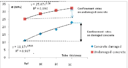
The figure 2 clearly shows that the strength and ductility of concrete cylinders are dependent of the state of damage of the concrete and the thickness of the polymer tube. The ultimate strength values of various confined concrete cylinders are plotted in Figure 3. Increasing the thickness of polymer tube causes increase strength and ductility of the specimen and the confinement effect is very important for the damaged concrete cylinder comparatively to the reference concrete cylinder.
In the elastic phase (start of loading), the evolution of the force - displacement is described by a linear line. All confined and unconfined undamaged concrete cylinders are in a non-cracked state. The confinement rate produced by the polymer tube is very low, or negligible.
Figure2- Stress–Strain curves comparison: a) Undamaged concrete, b) Damaged concrete
Figure3-Ultimate strength values for all tested concrete cylinders
0 5 10 15 20 25 30 35 40 CC Ref CC 1 PT CC 2 PT CC 3 PT Damaged concrete Undamaged concrete 32,81 35,08 11,18 15,96 MPa 29,27 25,2 19,02 22,73 a) a) b)
Figure 4-. Influence of the tube thickness on the ultimate compressive strength
a) undamaged concrete cylinder, b) damaged concrete cylinder
All the curves have the same slope. For the confined damaged concrete cylinders, the lateral confinement pressure is mobilized from the beginning of the loading and experiences a greater evolution with the increase of the axial load of compression.
When the compression effort increase, the confinement pressure on the concrete increase also (the confinement pressure is well mobilized). This confinement pressure makes it possible to reduce the propagation speed of the cracks, by opposing the rapid openings of the cracks. The propagation velocity of the stress field is greatly reduced. The confined concrete cylinder then carries a greater load compared to the reference concrete cylinder. The average ultimate strength value for the damaged concrete cylinder confined by three polymer tubes is 22.73 kN and it is almost equal to the strength of the reference cylinder, which is equal to 25.2 kN. Confinement for damaged concrete cylinders increases the rupture load by 42.75% for confinement with 1 tube, 70.12% in confinement with 2 tubes and 97.88% for confinement with 3 tubes, while in the case of undamaged concrete cylinders, confinement increases the rupture load by 16.15% for confinement with 1 tube, 30.2% in confinement with 2 tubes and 39.21% for confinement with 3 tubes. With respect to the last branch of the curves, after the peak, all the cylinders have almost the same shape of evolution, the displacement increases very rapidly with a small increase in the load and then the resistance is reduced and the speed is accelerated until the final rupture of the cylinder.
Analysis of the results obtained from the various compression tests carried out on the various short concrete cylinders shows that the ultimate stresses at the peak depend of the thickness of the polymer tube as depicted in fig 4, and the confinement effect is higher for the damaged concrete cylinders comparatively to the undamaged concrete cylinder.
3.2. Failure mechanisms analysis
Fig. 5 shows the failure mechanisms of the different studied concrete cylinders specimens. The failure of the concrete cylinder is achieved after the appearance of the axial cracks. This failure mechanism occurs more brutally than the failure mechanism of the confined concrete cylinder, which provides a higher level of compressive strength and ductility which is clearly visible in Fig.2.
B. Moussaoui et al. / Procedia Structural Integrity 5 (2017) 163–170 169 6 Moussaoui Boualem , Ait tahar Kamal &Bouamra Youcef / StructuralIntegrity Procedia 00 (2017) 000–000
Figure 4-. Influence of the tube thickness on the ultimate compressive strength
a) undamaged concrete cylinder, b) damaged concrete cylinder
All the curves have the same slope. For the confined damaged concrete cylinders, the lateral confinement pressure is mobilized from the beginning of the loading and experiences a greater evolution with the increase of the axial load of compression.
When the compression effort increase, the confinement pressure on the concrete increase also (the confinement pressure is well mobilized). This confinement pressure makes it possible to reduce the propagation speed of the cracks, by opposing the rapid openings of the cracks. The propagation velocity of the stress field is greatly reduced. The confined concrete cylinder then carries a greater load compared to the reference concrete cylinder. The average ultimate strength value for the damaged concrete cylinder confined by three polymer tubes is 22.73 kN and it is almost equal to the strength of the reference cylinder, which is equal to 25.2 kN. Confinement for damaged concrete cylinders increases the rupture load by 42.75% for confinement with 1 tube, 70.12% in confinement with 2 tubes and 97.88% for confinement with 3 tubes, while in the case of undamaged concrete cylinders, confinement increases the rupture load by 16.15% for confinement with 1 tube, 30.2% in confinement with 2 tubes and 39.21% for confinement with 3 tubes. With respect to the last branch of the curves, after the peak, all the cylinders have almost the same shape of evolution, the displacement increases very rapidly with a small increase in the load and then the resistance is reduced and the speed is accelerated until the final rupture of the cylinder.
Analysis of the results obtained from the various compression tests carried out on the various short concrete cylinders shows that the ultimate stresses at the peak depend of the thickness of the polymer tube as depicted in fig 4, and the confinement effect is higher for the damaged concrete cylinders comparatively to the undamaged concrete cylinder.
3.2. Failure mechanisms analysis
Fig. 5 shows the failure mechanisms of the different studied concrete cylinders specimens. The failure of the concrete cylinder is achieved after the appearance of the axial cracks. This failure mechanism occurs more brutally than the failure mechanism of the confined concrete cylinder, which provides a higher level of compressive strength and ductility which is clearly visible in Fig.2.
Figure 5-. Failure mechanisms of the tested concrete cylinders
The propagation of stresses caused by the radial deformations of the cylindrical specimen is also prevented, through the mobilization of the lateral pressure due to the polymer tube; the concrete crack is therefore trapped inside the polymer tube, which allows to increase the load corresponding to the crack propagation and to ensure a relatively ductile behavior.
In all cases, the rupture of the concrete cylinders is obtained once the polymer tube is ruptured (whatever the thickness of the polymer tube. For damaged concrete cylinders, crushing and dislocation of the concrete pieces trapped inside the tube is observed. For the confined concrete cylinders the failure mechanism occurs when the tube is bursting, as depicted by fig 5. The burst of the tube produces a great noise.
4. Conclusions
The experimental investigation allows us to observe the failure mode of the confined concrete cylinders and to evaluate the contribution of the polymer tube in increasing of the strength, and confinement level. It enables us to observe the differences in strengths between the reference concrete cylinder and the confined cylinder. The results given in the form of curves of loads - axial displacements show that the ultimate load and correspondent ultimate displacement are influenced by the thickness of the polymer tube and the degree of damage of the concrete.
The experimental results show that, with respect to the reference cylinder, the ultimate compressive strength of the cylinders confined by 3 polymer tubes increases by about 97.88%. In this case, the radius of the confined cylinder is increased by only 6-8 mm. also, Test results shows clearly the improvement of the confinement rate of the damaged concrete cylinder nearly about to 2,5 times compared to the confined undamaged concrete cylinder. Finally, the lateral confinement pressure does not vary linearly with the thickness of the polymer tube. In this respect, it is thus necessary to continue the work by a theoretical and numerical study to develop an analytical model that allows to apprehend the real behavior and to highlight the different conclusions formulated in this experimental work.
References
[1] [2] [3] [4] [5] [6] [7] [8] [9] [10] [11] [12] [13] [14] [15] [16] [17] [18]
Bentayeb F, Ait tahar K., Chateauneuf A. New technique for reinforcement of concrete columns confined by embedded composite grid. Constr Build Mate 2008; 22: 1624–1633
Ahmad, S.H. and Shah, S.P. “Stress-strain curves of concrete confined by spiral reinforcement”, ACI Journal, Vol. 79, No. 6, pp. 484-490, 1982.
Mirmiran. A., Shahawy, M., “Behavior of concrete columns confined with fiber composites”, Journal of Structural Engineering, ASCE, Vol. 123, pp. 583-590, 1997.
Saadatmanesh, H., Ehsani, M. R. and Li, M. W. “Strength and ductility of concrete columns externally reinforced with fiber composite straps”, ACI Structural journal, Vol. 91, No.4, pp. 434-447, 1994.
Xiao, Y., Wu, H. “Compressive behavior of concrete confined by various types of FRP composite jackets”, Journal of Reinforced Plastics and Composites, Vol. 22, No. 13, pp. 1187-1201, 2003.
Mander, J. B., Priestley, M.J.N. and Park, R. “Theoretical stress-strain model for confined concrete”, Journal of Structural Engineering, ASCE, Vol. 114, No.8, pp. 1804- 1826, 1988.
Fardis, M.N., Khalili, H.H., “Concrete encased in fiber glass-reinforced plastic”, ACI Material Journal Proceedings, Vol. 78, No. 6, pp. 440-446, 1981.
Berthet, J.F., Ferrier E. and Hamelin P. “Compressive behavior of concrete externally confined by composite jackets- Part A: Experimental study”, Construction and Building Materials, Vol. 19, pp. 223-232, 2005.
Saafi, M., Toutanji, H.A. and Li, Z. “Behavior of concrete columns confined with fiber reinforced polymer tubes”, ACI Materials Journal, Vol. 96, No. 4, pp. 500-509, 1999
Ait tahar K. and al. Parametric analysis of the models of confinement of the concrete column. Key Engineering Materials Vol. 498 (2012) pp1-14 d.
Nanni, A., Bradford, N.M. “FRP jacketed concrete under uniaxial compression”, Construction and Building Materials, Vol. 9, No. 2, pp. 115-124, 1995.
Saafi, M., Toutanji, H.A. and Li, Z. “Behavior of concrete columns confined with fiber reinforced polymer tubes”, ACI Materials Journal, Vol. 96, No. 4, pp. 500-509, 1999.
Mander, J. B., Priestley, M.J.N. and Park, R. “Theoretical stress-strain model for confined concrete”, Journal of Structural Engineering, ASCE, Vol. 114, No.8, pp. 1804- 1826, 1988.
Ait tahar K, Chateauneuf A, ‘Confinement of the Concrete Structures by Embedded Composite Grids’’ journal Key Engineering Materials Vol. 425, 2010 pp 195-216
Karbahari, V. M., and Gao, Y. “Composite Jacketed concrete under uniaxial compression-verification of simple design equations”, Journal of Materials in Civil Engineering, ASCE, Vol. 9, No. 4, pp. 185-193, 1997. Sheikh, S.A., Uzumeri, S.M. “Strength and ductility of tied concrete columns”, Journal of Structural Division, ASCE, Vol. 106, No. 5, pp. 1079-1102, 1980.
Wu G, Lü Z.T, Wu Z.S , Strength and ductility of concrete cylinders confined with FRP composites, Const. Build..Mat. N°.20, 2006, pages 134-148
Kurt, C.E. “Concrete filled structural plastic columns”, Proceedings of the American Society of civil engineering, Vol. 104, No. ST1, pp. 55-63, 1978 .