HAL Id: hal-02264893
https://hal.archives-ouvertes.fr/hal-02264893
Submitted on 7 Aug 2019
HAL is a multi-disciplinary open access
archive for the deposit and dissemination of
sci-entific research documents, whether they are
pub-lished or not. The documents may come from
teaching and research institutions in France or
abroad, or from public or private research centers.
L’archive ouverte pluridisciplinaire HAL, est
destinée au dépôt et à la diffusion de documents
scientifiques de niveau recherche, publiés ou non,
émanant des établissements d’enseignement et de
recherche français ou étrangers, des laboratoires
publics ou privés.
Type Synthesis of Kinematically Redundant 3T1R
Parallel Manipulators
Xianwen Kong, Damien Chablat, Stéphane Caro, Jingjun Yu, Clément
Gosselin
To cite this version:
Xianwen Kong, Damien Chablat, Stéphane Caro, Jingjun Yu, Clément Gosselin. Type Synthesis of
Kinematically Redundant 3T1R Parallel Manipulators. ASME 2013 International Design
Engineer-ing Technical Conferences and Computers and Information in EngineerEngineer-ing Conference, Aug 2013,
Portland, United States. pp.V06AT07A047, �10.1115/DETC2013-12575�. �hal-02264893�
Proceedings of the ASME 2013 International Design Engineering Technical Conferences & Computers and Information in Engineering Conference IDETC/CIE 2013 August 4–7, 2013, Oregon, Portland, USA
DETC2013-12575
TYPE SYNTHESIS OF KINEMATICALLY REDUNDANT 3T1R PARALLEL MANIPULATORS
Xianwen Kong
School of Engineering and Physical Sciences Heriot-Watt University
Edinburgh, UK, EH14 4AS email: [email protected]
Damien Chablat and St ´ephane Caro
Institut de Recherche en Communications et Cybern ´etique de Nantes
UMR CNRS n 6597, 1 rue de la No ¨e, 44321 Nantes email: (stephane.caro, damien.chablat)@irccyn.ec-nantes.fr
Jingjun Yu
Robotics Institute
School of Mechanical Engineering and Automation Beihang University
Beijing 100191, China email: [email protected]
Cl ´ement Gosselin
D ´epartement de G ´enie M ´ecanique Universit ´e Laval
Pavillon Adrien-Pouliot, 1065 Avenue de la m ´edecine Qu ´ebec, Qu ´ebec, Canada, G1V 0A6
email: [email protected]
ABSTRACT
A kinematically redundant parallel manipulator (PM) is a PM whose degrees-of-freedom (DOF) are greater than the DOF of the moving platform. It has been revealed in the literature that a kinematically redundant PM has fewer Type II kinematic singular configurations (also called forward kinematic singular configurations, static singular configurations or parallel singu-lar configurations) and/or constraint singusingu-lar configurations than its non-redundant counterparts. However, kinematically redun-dant PMs have not been fully explored, and the type synthesis of kinematically redundant PMs is one of the open issues. This paper deals with the type synthesis of kinematically redundant 3T1R PMs (also called SCARA PMs or Schoenflies motion gen-erators), in which the moving platform has four DOF with re-spect to the base. At first, the virtual-chain approach to the type synthesis of kinematically redundant parallel mechanisms is re-called. Using this approach, kinematically redundant 3T1R PMs are constructed using several compositional units with very few mathematical derivations. The type synthesis of 5-DOF 3T1R PMs composed of only revolute joints is then dealt with sys-tematically. This work provides a solid foundation for further research on kinematically redundant 3T1R PMs.
KEY WORDS Parallel manipulator, Kinematically redun-dant parallel manipulator, Type synthesis, Virtual-chain ap-proach, Screw theory
NOMENCLATURE
3T1R Three-DOF translation and one-DOF rotation.
C Order of the twist system (also the connectivity) of the mov-ing platform of a parallel manipulator.
c Order of the wrench system of a parallel manipulator. ci Order of the wrench system of the i-th leg.
fi Sum of DOF of all the joints in leg i.
F DOF of a parallel manipulator. P Prismatic joint.
PKC Parallel kinematic chain. PM Parallel manipulator.
PPPR= PPPR virtual-chain equivalent. R Revolute joint.
˝
R R joints within a 3T1R PM whose axes are parallel to the axes of rotation of the 3T1R motion.
`
R R joints except for the ˝R joints within a leg that have parallel axes.
R Actuated R joint.
R Redundant DOF of a parallel manipulator. Ri Redundant DOF of leg i.
V= Virtual-chain equivalent.
W Wrench system of a parallel manipulator. Wi Leg wrench system of leg i.
ζ0 A wrench of zero-pitch (or constraint force).
ζ∞ A wrench of∞-pitch (or constraint couple).
1 INTRODUCTION
During the past decade, great advances have been made on the type synthesis of parallel mechanisms (PMs). In addition to a large number of PMs (see [1–8] for example), several systematic
approaches have been proposed for the type synthesis of PMs, such as the method based on the displacement group [2, 9–15], the method based on screw theory [16–19], the single-opened-chain approach [20], the virtual-single-opened-chain approach [21, 22], the linear transformation approach [23] and other approaches such as [24].
While most works have been focusing on non-redundant PMs, several works on redundant PMs, including redundantly actuated PMs and kinematically redundant PMs, have also been published [4, 25–32]. In a kinematically redundant PM, the degrees-of-freedom (DOF) of the PM are greater than the DOF of the moving platform (also the connectivity of the moving plat-form with respect to the base). It has been revealed that a kine-matically redundant PM has fewer Type II kinematic singular configurations than its non-redundant counterpart [29, 30]. Re-cently, a systematic study on the type synthesis of kinematically redundant translational PMs has been published in [31], where the characteristics of kinematically redundant translational PMs have been identified as compared with their associated non-redundant counterparts from the perspective of constraint singu-larity and Type II kinematic singusingu-larity. Kinematically redundant PMs have been classified into four categories: (a) PMs that have fewer constraint singularities and Type II kinematic singularities than the associated non-redundant PMs, (b) PMs that have fewer constraint singularities than the associated non-redundant PMs, (c) PMs that have fewer Type II kinematic singularities than the associated non-redundant PMs and (d) PMs that have the same constraint singularities and Type II kinematic singularities as the associated non-redundant PMs. Considering the needs of 3T1R PMs (also PPPR= PMs [22], SCARA PMs or Schoenflies mo-tion generators) and the fact that a 3T1R PM may suffer from constraint singularities and Type II singularities [33], this paper will focus on the type synthesis of kinematically redundant 3T1R PMs, which is still an open issue.
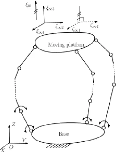
In this paper, the type synthesis of kinematically redundant 3T1R PMs will be investigated. The virtual-chain approach to the type synthesis of kinematically redundant PMs [21, 22, 31] will be recalled in Section 2. In Sections 3–6, the type synthe-sis of 5-DOF 3T1R PMs (Fig. 1) will be dealt with in detail. Here and throughout this paper, ζ∞(ζ0) denotes a wrench of
∞-pitch (0-∞-pitch) representing a constraint couple (force). ξ∞(ξ0)
denotes a twist of∞-pitch (0-pitch) representing a translation (rotation). Finally, conclusions will be drawn.
Due to space limitation, we confine ourselves to the type synthesis of 5-DOF 3T1R PMs involving only R (revolute) joints. For simplicity reasons, here and throughout this paper, R denotes actuated R joints. ˝R denotes R joints within the same 3T1R PM whose axes are parallel to the axes of rotation of the 3T1R motion. ´R or `R denotes R joints with parallel axes within a single-loop kinematic chain or a leg of PMs but are not parallel to the axes of the ˝R joints.
2 THE VIRTUAL-CHAIN APPROACH
In [21, 22, 31], a virtual-chain approach has been proposed to the type synthesis of non-redundant and kinematically redun-dant PMs. Families of PMs have been constructed using sev-eral classes of compositional units. One of the characteristics
Base Moving platform X Y Z O ξ∞2 ξ∞3 ξ∞1 ζ∞2 ζ∞1 ξ01 Fig. 1 A 5-DOF PPPR= PMs. Base Moving platform PPPR virtual chain X Y Z O
Fig. 2 PPPR virtual chain.
of the virtual-chain approach is that few derivations are needed. In [34, 35], the virtual-chain approach has been extended to the type synthesis of PMs with multiple operation modes. This sec-tion will recall the virtual-chain approach to the type synthesis of kinematically redundant PMs.
2.1 Virtual chain
Different applications may have different motion patterns. Vir-tual chains were introduced in [22] to represent the motion pat-terns of PMs. For example, 3T1R motion, one of the commonly used motion patterns, can be represented with a PPPR virtual chain (Fig. 2). For clarity, a virtual chain is encircled by a rect-angle drawn with dashed lines. The wrench system of the PPPR virtual chain is a 2-ζ∞-system.
2.2 Instantaneous mobility analysis of kinematic chains
The instantaneous mobility analysis of kinematic chains is the starting point in the type synthesis of PMs if the virtual-chain approach is applied.
During the past few years, several formulas (see [22, 23, 36] for example) have been proposed to calculate the DOF of PMs. The instantaneous mobility criteria proposed in [22] based on screw theory is recalled below.
ζ∞
Fig. 3 `R `R `R `R ´R ´RPPP single-loop kinematic chain.
2.2.1 Single-loop kinematic chain The instanta-neous mobility,F, of a single-loop kinematic chain is
F = f − 6 + c. (1) where f denotes the sum of DOF of all the joints, and c denotes the order of the common wrench system, which is the reciprocal system of the twist system composed of all the joint twists, of the single-loop kinematic chain.
Let us take the `R `R `R `R ´R ´RPPP single-loop kinematic chain (Fig. 3) as an example. For this kinematic chain, the common wrench system is a 1-ζ∞-system. The basis wrench of the 1-ζ∞
-system is the ζ∞whose direction is perpendicular to the axes of
all the R joints. One then has c = 1. In addition, one has f = 9. Using Eq.(1), one obtains the DOF of the kinematic chain as
F = f − 6 + c = 9 − 6 + 1 = 4.
2.2.2 Parallel kinematic chains Consider an m-legged parallel kinematic chain (PKC) (Fig. 4). The wrench sys-tem of a PKC [Fig. 4(a)] is equal to the sum of the leg-wrench systems [Fig. 4(b)], i.e.,
W =
m
X
i=1
Wi (2)
LetC denote the order of the twist system of the PKC (also the connectivity). Riand R denote the redundant DOF of leg i and the PKC respectively. c andF denote the order of the wrench system,W, and DOF of the PKC. ci and fi denote the order of the leg wrench system,Wi, and the sum of DOF of all the joints in leg i. One has
C = 6 − c (3) R = m X i=1 Ri (4) Ri = fi− (6 − ci) = fi− 6 + ci (5) The DOF of the PKC is
F = C + R = C + m X i=1 Ri = 6− c + m X i=1 Ri (6) Base ζ∞2 ζ∞1 ζ∞3 Leg 1 Leg 2 Leg 3 (a) The PKC. Base Leg 1 ζ∞1 ζ∞2 (b) Leg 1. Fig. 4 3-P ´R ´R ´R ´R PKC.
The DOF obtained using Eq. (6) is usually instantaneous. If c, ciand Riare the same in different general configurations, the
DOF is full-cycle.
In addition to the mobility, another important index, the number of overconstraints or redundant constraints ∆, of a PKC is defined as ∆ = m X i=1 ci− c (7)
Consider the 3-P ´R ´R ´R ´R PKC [32] shown in Fig. 4. In this PKC, all the axes of the R joints within a same leg are parallel. The direction of a P joint is not perpendicular to the axes of the R joints within the same leg. Not all the axes of the R joints on the moving platform are parallel. The wrench system of each leg is a 2-ζ∞-system [Fig. 4(b)]. The wrench system of the PKC is the 2-ζ∞-system [Fig. 4(a)]. One has ci = 2, c = 3, Ri =
5− (6 − 2) = 1 and m = 3. Then one obtains C = 6 − c = 3 F = C + 3 X i=1 Ri= 6 and ∆ = 3 X i=1 ci− c = 6 − 3 = 3.
To facilitate the type synthesis of PMs, we substitute Eq. (7) into Eq. (6) and then obtain
m
X
i=1
ci= 6− C + ∆ = 6 − F + R + ∆ (8)
Equations (4), (5) and (2) can then be respectively rewritten as
m X i=1 Ri = R (9) fi= 6 + Ri− ci (10) m X i=1 Wi= W. (11)
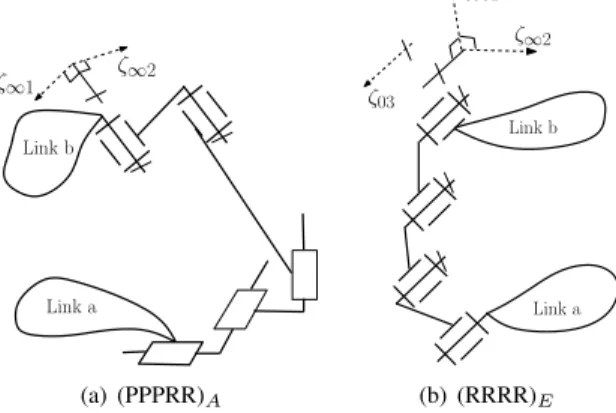
Link a Link b ζ∞1 ζ∞2 (a) (PPPRR)A Link b Link a ζ∞1 ζ∞2 ζ03 (b) (RRRR)E
Fig. 5 Example compositional units.
2.3 Compositional units
If one uses only the instantaneous mobility criteria to perform the type synthesis of PMs, there is no guarantee that the PMs can undergo the desired finite motion. Compositional units are there-fore identified in [22] using which PMs with full-cycle mobility can be constructed directly.
A compositional unit is a serial kinematic chain with the following kinematic characteristic: In any configuration of a compositional unit, its wrench system always includes a spec-ified number of independent wrenches of zero-pitch or infinity-pitch. The compositional units will be used in the construction of single-loop kinematic chains and PKCs. Only two classes of compositional units (Fig. 5) that will be used in the type synthesis of PPPR= PMs are recalled below.
• Parallelaxis compositional units. A parallelaxis composi-tional unit is a serial kinematic chain composed of at least one R joint and at least one P joint in which the axes of all the R joints are parallel and not all the directions of the P joints are perpendicular to the axes of the R joints. The characteristic of a compositional unit of this class is that the axes of all the R joints are always parallel. The wrench system of this compositional unit always includes a 2-ζ∞ -system. The 2-ζ∞-system is composed of all the ζ∞whose directions are perpendicular to all the axes of the R joints [Fig. 5(a)]. A parallelaxis compositional unit is denoted by ()A.
• Planar compositional units. A planar compositional unit is a serial kinematic chain composed of at least two R and/or P joints which include at least one R joint and in which all the links are moving along parallel planes. In a composi-tional unit of this class, the axes of all the R joints are par-allel, and the direction of each P joint is perpendicular to all the axes of the R joints. The wrench system of this com-positional unit always includes a 2-ζ∞-1-ζ0-system. The 2-ζ∞-1-ζ0-system is composed of all the ζ0 whose axes are parallel to the axes of the R joints as well as all the ζ∞ whose directions are perpendicular to the axes of all the R joints [Fig. 5(b)]. A planar compositional unit is denoted by ()E. Base Moving platform X Y Z O ξ∞2 ξ∞3 ξ∞1 ζ∞2 ζ∞1 ξ01
Fig. 6 A 5-DOF PPPR= parallel mechanisms with a PPPR virtual chain added.
2.4 Conditions for a PKC to be anF-DOF V= PKC
Let us consider anF-DOF V= PKC (Fig. 1). When one connects the base and the moving platform of a PKC by an appropriate virtual chain (Fig. 2) matching the motion pattern of the PKC, the function of the PKC is not affected (Fig. 6). It is apparent that a PKC is anF-DOF V= PKC if it satisfies the following three conditions:
(1) The redundant DOF, Ri, of the legs satisfy m
X
i=1
Ri=F − C = F + c − 6 (12)
(2) Each leg of the PKC and the same virtual chain constitute a (C + Ri)-DOF single-loop kinematic chain.
(3) The wrench system of the PKC is the same as that of the virtual chain in any general configuration.
Conditions (1) and (2) for V= PKCs guarantee that the mov-ing platform can undergo the V= motion and the DOF of the PM is at leastF, while Condition (3) for V= PKCs further guarantees that the DOF of the moving platform is the same as that of the virtual chain and the DOF of the PKC isF.
2.5 Systematic type synthesis of V= parallel mecha-nisms
Based on the above conditions, a general systematic procedure can be proposed for the type synthesis ofF-DOF V= PMs. The proposed procedure can be divided into four steps, namely: Step 1 Determination of the combinations of leg structural
pa-rameters. Step 1 can be performed using Eqs. (11), (8) and (9).
Step 2 Type synthesis of legs for V= PKCs.
According to Condition (2) of V= PKCs, each leg, together with a virtual chain, forms a (C+Ri)-DOF single-loop kine-matic chain. For a set of leg structural parameter ciand Ri
ζi ∞1 ζi ∞1 ζi ∞2 (b) 1-ζi ∞system (a) 2-ζi ∞system
Fig. 7 Leg-wrench systems (ci> 0) of PPPR= PKCs.
obtained in Step 1, the types of legs can be obtained by con-structing (C + Ri)-DOF single-loop kinematic chains using
the compositional units and then removing the virtual chain from these single-loop kinematic chains.
Step 3 Assembly of legs for V= PKCs.
The m-legged V= PKCs can be generated by assembling m legs for V= PKCs that are obtained in Step 2 according to the combinations of leg structural parameters obtained in Step 1, such that the sum of the leg-wrench systems is the same as that of the virtual chain (Condition (3) for V= PKCs). The conditions, if any, can be easily satisfied by inspection.
Step 4 Selection of actuated joints.
V= PMs can be generated by selecting the actuated joints for each V= PKC obtained in Step 3.
3 STEP 1: DETERMINATION OF THE COMBINATIONS OF LEG STRUCTURAL PARAMETERS
For the PPPR= PKC and a specified number of overconstraints ∆, the combinations of leg structural parameters of a PKC can be determined using Eqs. (11), (8) and (9).
In any general configuration, the wrench system of a PPPR= PKC is the same as that of its PPPR virtual chain, i.e., a 2-ζ∞ -system (Eq. (11)). It then follows that any leg-wrench -system with order ci> 0 of a PPPR= PKC is the 2-ζ
∞-system or 1-ζ∞
-system (Fig. 7). Since all the wrenches in the wrench -systems, W, and the leg-wrench systems, Wi, are of the same pitch, the
combinations of leg-wrench systems can be simply represented by the combinations of the orders, ci, of leg-wrench systems.
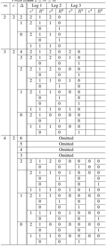
The combinations of the orders, ci, of leg-wrench systems can be determined by solving Eq. (8). Using Eq. (9) , one can further determine the combination of redundant DOF of legs. Ta-ble 1 shows all the combinations of leg structural parameters ci and Rifor m(2
≤ m ≤ C)-legged 5-DOF PPPR= PKCs. The combinations of leg structural parameters corresponding to all possible values of ∆ have been listed for completeness.
From Table 1, one obtains that there are six sets of structural parameters, ci and Ri, of legs for 5-DOF PPPR= PKCs (Table
2).
4 STEP 2: TYPE SYNTHESIS OF LEGS
Once the structural parameters of legs have been obtained, the types of legs with ci > 0 can be constructed using the composi-tional units as follows1. The type synthesis of legs with structural
1Types of legs with ci= 0 have been well documented in the literature and
are therefore not discussed in this paper. In addition, the types of legs with
inac-Table 1 Combinations ofciandRiform-legged 5-DOF PPPR=
PKCs (Case2≤ m ≤ 3)
m c ∆ Leg 1 Leg 2 Leg 3
c1 R1 c2 R2 c3 R3 c4 R4 2 2 2 2 1 2 0 1 2 1 1 0 0 1 0 2 1 1 0 0 1 1 1 1 0 3 2 4 2 1 2 0 2 0 3 2 1 2 0 1 0 0 0 1 2 2 1 2 0 0 0 0 0 1 2 1 1 0 1 0 0 1 0 1 2 1 1 0 0 0 0 1 0 0 0 1 1 1 1 0 1 0 0 2 1 0 0 0 0 0 1 0 1 1 1 0 0 0 0 0 1 4 2 6 Omitted 5 Omitted 4 Omitted 3 Omitted 2 2 1 2 0 0 0 0 0 0 0 1 0 0 2 1 1 0 1 0 0 0 0 1 0 0 0 0 0 1 1 1 1 0 1 0 1 0 1 2 1 1 0 0 0 0 0 0 1 0 0 0 0 1 0 1 1 1 0 1 0 0 0 0 0 0 1 0 2 1 0 0 0 0 0 0 0 0 0 1 1 1 1 0 0 0 0 0 0 0 1
Table 2 Structural parameters, ci and Ri, of legs for 5-DOF
PPPR= PKCs.
Ri 0 1
ci 2 1 0 2 1 0 fi 4 5 6 5 6 7
parameters ci = 1 and Ri = 1 will be used as an example to il-lustrate the synthesis procedure.
4.1 Step 2a: Calculate the number of joints in a leg
The number of joints in a leg with structural parameters ci and Ri can be obtained using Eq. (10). For example, for legs with
structural parameters ci= 1 and Ri= 1, one has
fi= 6 + Ri− ci= 6 + 1− 1 = 6.
All the numbers of joints of legs for 5-DOF PPPR= PKCs ob-tained are shown in the third row of Table 2.
4.2 Step 2b: Type synthesis of (C + Ri)-DOF
single-loop kinematic chains
A (C + Ri)-DOF single-loop kinematic chain that contains the
PPPR= virtual chain and has Wi as its common wrench
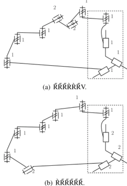
sys-tem can be constructed using the compositional units. Accord-ing to [22], a 5-DOF sAccord-ingle-loop kinematic chain with a 1-ζ∞ -system as its common wrench -system is composed of two spa-tial Parallelaxis and/or planar compositional units. Figure 8 shows two of the 5-DOF single-loop kinematic chains. For ex-ample, the ˝R ˝R ˝R `R `R ˝RV single-loop kinematic chain shown in Fig. 8(a) is composed of one spatial Parallelaxis compositional unit, ˝R ˝R ˝R `R `R ˝RV denoted by 1, and one planar compositional unit, `R `R denoted by 2. The basis wrench of the 1-ζ∞-system of the single-loop kinematic chain is the ζ∞whose direction is perpendicular to the axes of all the R joints.
4.3 Step 2c: Discard single-loop kinematic chains in which the twists of all the joints but the PPPR= virtual chain are reciprocal to a ζ that does not belong to the wrench system of the virtual chain.
In a (C + Ri)-DOF single-loop kinematic chain that contains the PPPR= virtual chain and hasWias its common wrench system obtained in Step 2b, the wrench system of the serial kinematic chain composed of all the joints except the PPPR= virtual chain containsWi. In order to ensure the wrench system of the serial kinematic chain composed of all the joints except the PPPR= vir-tual chain isWi, one needs to discard the single-loop kinematic chains in which the twists of all the joints but the PPPR= virtual chain are reciprocal to a ζ that does not belong to the wrench system of the PPPR= virtual chain.
For example, the `R ˝R ˝R ˝R ˝R ˝RV kinematic chain [Fig. 8(b)] should be discarded since the twists of the six R-joints are re-ciprocal to any ζ0with its axis parallel to the axes of the ˝R joints and intersects the axis of the `R joint. Such a ζ0does not belong to the wrench system of the PPPR virtual chain.
tive joints [18, 22] will not be discussed in this paper due to space limitation.
1 1 1 1 1 1 1 1 2 2 (a) ˝R ˝R ˝R `R `R ˝RV. 1 1 1 1 1 1 2 2 2 2 (b) `R ˝R ˝R ˝R ˝R ˝R.
Fig. 8 Two 5-DOF single-loop kinematic chains.
4.4 Step 2d: Generation of types of legs
In each of the (C + Ri)-DOF single-loop kinematic chains
ob-tained in step 2c, the wrench system of the serial kinematic chain composed of all the joints except the PPPR= virtual chain isWi. Therefore, the types of legs for PPPR= PMs can be readily ob-tained by removing the virtual chains from the (C + Ri)-DOF single-loop kinematic chains.
In removing the virtual chain, the specific geometric condi-tions that the joint axes or direccondi-tions satisfy before removing the virtual chain need to be satisfied by the leg. Such conditions can be easily indicated by the notations introduced before.
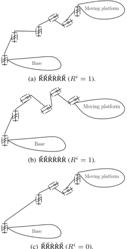
For example, by removing the PPPR virtual chain from the 5-DOF ˝R ˝R ˝R `R `R ˝RV single-loop kinematic chain [Fig. 8(a)], one obtains an ˝R ˝R ˝R `R `R ˝R leg for PPPR= PKCs (Fig. 9(a)). The wrench system of this leg is a 1-ζ∞-system, the basis wrench of which is the ζ∞whose direction is perpendicular to the axes of all the R joints.
A number of legs for 5-DOF PPPR= PMs have been ob-tained. The geometric conditions that the legs satisfy are summa-rized in Table 3. One can easily list the types of legs according to these geometric conditions. For example, in legs for PPPR= PMs with structural parameters ci= 1 and Ri= 1, one can obtain the
following 11 types of legs composed of six R joints. ˝ R ˝R ˝R ˝R `R `R, ˝R ˝R ˝R `R `R ˝R, ˝R ˝R `R `R ˝R ˝R, ˝R `R `R ˝R ˝R ˝R, `R `R ˝R ˝R ˝R ˝R, ˝ R ˝R ˝R `R `R `R, ˝R ˝R `R `R `R ˝R, ˝R `R `R `R ˝R ˝R, `R `R `R ˝R ˝R ˝R, ˝R ˝R `R `R `R `R and ˝ R `R `R `R `R ˝R.
5 STEP 3: ASSEMBLY OF LEGS
The type synthesis of PPPR= PKCs consists in obtaining the types of PPPR= PKCs by assembling the legs obtained in Step 2 according to the combinations of leg structural parameters ob-tained in Step 1. In the assembly of legs, conditions that guar-antee that the sum of all the leg-wrench systems constitutes a 2-ζ∞-system (Conditions (3) for V= PKCs) should be revealed,
Table 3 Legs for PPPR= PKCs (CasesRi=0 or 1)
Ri Class No. Type Description Leg-wrench system 0 5R 1 R ˝˝R ˝R `R `R
The axes of two or three successive `R joints within a leg are parallel, while the axes of the re-maining joints are ˝R joints whose axes are par-allel to the axes of rotation in the 3T1R PM.
1-ζ∞-system 2 R ˝˝R `R `R ˝R 3 R `˝R `R ˝R ˝R 4 R ``R ˝R ˝R ˝R 5 R ˝˝R `R `R `R 6 R `˝R `R `R ˝R 7 R ``R `R ˝R ˝R 1 6R 8 R ˝˝R ˝R ˝R `R `R 9 R ˝˝R ˝R `R `R ˝R 10 R ˝˝R `R `R ˝R ˝R 11 R `˝R `R ˝R ˝R ˝R 12 R ``R ˝R ˝R ˝R ˝R 13 R ˝˝R ˝R `R `R `R 14 R ˝˝R `R `R `R ˝R 15 R `˝R `R `R ˝R ˝R 16 R ``R `R ˝R ˝R ˝R 17 R ˝˝R `R `R `R `R 18 R `˝R `R `R `R ˝R Base Moving platform (a) ˝R ˝R ˝R `R `R ˝R (Ri= 1). Base Moving platform (b) ˝R ˝R `R `R `R `R (Ri= 1). Base Moving platform (c) ˝R ˝R `R `R ˝R (Ri= 0).
Fig. 9 Several legs for PPPR= PMs with a 1-ζ∞-system.
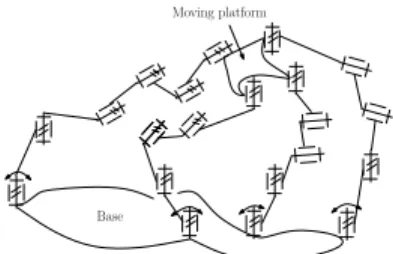
For example, one combination of leg structural parameters for the 5-DOF PPPR= PMs are c1= 1, R1= 1, c2= 1, R2= 0, c3 = 1, R3 = 0 , c4 = 1, and R4 = 0 (see the 10throw from the last in Table 1). According to Step 2, one type of the legs
Moving platform
Base
Fig. 10 ˝R ˝R ˝R `R `R ˝R-3- ˝R ˝R `R `R ˝R PPPR= PKC.
with structural parameter c1 = 1 and R1 = 1 is an ˝R ˝R ˝R `R `R ˝R
leg (Fig. 9(a)). One type of the legs with structural parameter c1 = 1 and R1 = 0 is an ˝R ˝R `R `R ˝R leg (Fig. 9(c)). By
assem-bling one ˝R ˝R ˝R `R `R ˝R leg and three ˝R ˝R `R `R ˝R legs, one obtains the ˝
R ˝R ˝R `R `R ˝R-3- ˝R ˝R `R `R ˝R PPPR= PKC shown in Fig. 10. The leg wrench system of leg i is a 1-ζ∞-system the basis wrench of
which is the ζ∞i whose direction is perpendicular to the axes of all the R joints. The direction of ζ∞i may vary with the position of the moving platform. In order to guarantee that the sum of ζ1
∞and ζ∞2 constitutes the 2-ζ∞-system in a general
configura-tion, the following case should be avoided: The axes of all the R joints on the moving platform (base) are parallel, and the axes of all the R joints on the base (moving platform) are parallel but are not parallel to the axes of R joints on the moving platform (base).
6 STEP 4: SELECTION OF ACTUATED JOINTS
The selection of actuated joints for PPPR= PMs involves finding all the possible PPPR= PMs for a given PPPR= PKC and remov-ing the cases for which the set of actuated joints is invalid.
Since finding all the candidate PPPR= PMs for a PPPR= PKC is trivial, only the validity condition that the actuated joints of PMs need to satisfy is given below:
Moving platform
Base
Fig. 11 ˝R ˝R ˝R `R `R ˝R-3- ˝R ˝R `R `R ˝R PPPR= PM.
Moving platform
Base
Fig. 12 ˝R ˝R `R `R `R `R-3- ˝R ˝R `R `R ˝R 5-DOF PPPR= PM with an idle DOF.
A set ofF actuated joints for an F-DOF PPPR= PM is valid if and only if, in a general configuration, all the basis wrenches of the actuation wrench systemsWi
6⊃ (i = 1, 2,· · · , m), of all
the legs, together with the basis wrenches, ζ∞1and ζ∞2, of the
wrench system of the PPPR= PKC constitute a basis of the 6-system.
As defined in [31], the actuated wrench system,Wi 6⊃, of leg
i is composed of all the wrenches that are reciprocal to the twists of all the joints in leg i except the actuated joints and do not belong to the wrench system,Wi, of the leg i.
The ˝R ˝R ˝R `R `R ˝R-3- ˝R ˝R `R `R ˝R PPPR= PM (Fig. 11) is one of the potential 5-DOF PPPR= PMs obtained from the ˝R ˝R ˝R `R `R ˝
R-3-˝
R ˝R `R `R ˝R PPPR= PKC. The leg actuation wrench system of each leg is a 1-ζ0-system the basis wrench of which is the ζ06⊃i whose
axis intersects the axes of all the unactuated R joints in the same leg. The axes of ζ06⊃i may vary with the pose of the moving plat-form. It can be verified that ζ06⊃1 , ζ06⊃2 , ζ06⊃3 and ζ06⊃4 , together with ζ∞1 and ζ∞2 , constitute a basis of the 6-wrench system in a gen-eral configuration. Therefore, the ˝R ˝R ˝R `R `R ˝R-3- ˝R ˝R `R `R ˝R PPPR= PM is valid.
A large number of 5-DOF PPPR= PMs can be obtained fol-lowing the above procedure. It is noted that there may exist PMs with idle DOF, which refer toF-DOF PMs in which less than F actuated joints can be used to fully control the motion of the moving platform. For example, the ˝R ˝R `R `R `R `R-3- ˝R ˝R `R `R ˝R 5-DOF PPPR= PM (Fig. 12), a set of four R joints can be used to fully control the motion of the moving platform [32]. One of the ´R joints in the ˝R ˝R `R `R `R `R leg has an idle DOF.
7 CONCLUSIONS
The type synthesis of 5-DOF PPPR= PMs has been studied and several types of 5-DOF PPPR= PMs have been obtained. The class of PPPR= PMs that have fewer constraint singularities and Type II kinematic singularities than their associated non-redundant PMs, such as the ˝R ˝R ˝R `R `R ˝R -3- ˝R ˝R ˝R `R `R ˝R PPPR= PM,
deserve further investigation.
This work, together with [31], lays the foundation to the op-timal type synthesis of kinematically redundant PMs and may contribute to the development of energy-efficient reconfigurable PMs.
ACKNOWLEDGMENT
The first three authors would like to thank the Royal Society, United Kingdom, through an International Joint Project No. JP100715. The first author acknowledges the financial support from the Engineering and Physical Sciences Research Council (EPSRC), United Kingdom, under grant No. EP/I016333/1. .
REFERENCES
[1] Clavel, R., 1990, “Device for the movement and positioning of an element in space,” United States Patent No. 4976582. [2] Herv´e, J.M. and Sparacino, F., 1991, “Structural synthesis
of parallel robots generating spatial translation,” Proc. of the fifth International Conference on Advanced Robotics, Pisa, Italy, Vol. 1, pp. 808–813.
[3] Gosselin, C.M., St-Pierre, E., and Gagn´e, M., 1996, “On the development of the Agile Eye: Mechanical design, control issues and experimentation,” IEEE Robot. & Autom. Maga-zine, vol. 3, no. 4, pp. 29-37.
[4] Kim, J., Park, F., Ryu, S., Kim, J., Park, C., and Iurascu, C., 2001, “Design and analysis of a redundantly actuated par-allel mechanism for rapid machining,” IEEE Trans. Robot. Autom., 17, pp. 423-434.
[5] Chablat, D. and Wenger, P., 2003, “Architecture optimiza-tion of a 3-DOF translaoptimiza-tional parallel mechanism for ma-chining applications, the Orthoglide,” IEEE Trans. Robot. Autom., vol. 19, no. 3, pp. 403–410.
[6] Angeles, J., Caro, S., Khan, W., and Morozov, A., 2006, “Kinetostatic design of an innovative Sch¨oenflies-motion generator,” Proc. Inst. Mech. Eng., Part C, J. Mech. Eng. Sci., vol. 200, no. 7, pp. 935-943.
[7] Richard, P.-L., Gosselin, C.,and Kong, X., 2007, “Kinematic analysis and prototyping of a partially decoupled 4-DOF 3T1R parallel manipulator,” ASME J. Mech. Des., vol. 129, no. 6, pp. 611-616.
[8] Pierrot, F., Nabat, F., Company, O., Krut, S., and Poignet, P., 2009, “Optimal design of a 4-DOF parallel manipulator: From academia to industry,” IEEE Trans. Robot., vol. 25, no. 2, pp. 213–224,.
[9] Herv´e, J.M., 1999, “The Lie group of rigid body displace-ments, a fundamental tool for mechanisms design,” Mech. Mach. Theory, vol. 34, no. 5, pp. 719–730.
[10] Angeles, J., 2004, “The qualitative synthesis of parallel ma-nipulators,” ASME J. Mech. Des., vol. 126, no. 4, pp. 617– 624.
[11] Li, Q. C., Huang, Z., and Herv´e, J. M., 2004, “Type synthe-sis of 3R2T 5-dof parallel mechanisms using the lie group of displacements,” IEEE Trans. Robot. Autom., vol. 20, no. 2, pp. 181-190.
[12] Lee, C. C. and Herv´e, J. M., 2006, “Translational parallel manipulators with doubly planar limbs,” Mech. Mach. The-ory, vol. 24, no. 4, pp. 433-455.
[13] Refaat, S., Herv´e, J.M.,, Nahavandi, S., and Trinh, H., 2007, “Two-mode over-constrained three-DOF rotational-translational linear-motor-based parallel kinematics mecha-nism for machine tool applications,” Robotica, vol. 25, no, 4, pp. 461–466.
[14] Salgado, O., Altuzarra, O. Amezua, E., and Hern´andez, A., 2007, “A parallelogram-based parallel manipulator for Sch¨onflies smotion,” ASME J. Mech. Design, vol. 129, No. 12, pp. 1243-1250.
[15] Meng, J., Liu, G. F., and Li, Z. X., 2007, “A geometric theory for synthesis and analysis of sub 6-DOF parallel ma-nipulators,” IEEE Trans. Robot., vol. 23, no. 4, pp. 625-649. [16] Huang, Z. and Li, Q.-C., 2002, “General Methodology for the type synthesis of lower-mobility symmetrical parallel manipulators and several novel manipulators,” Int. J. Robot. Res., vol. 21, no. 2, pp. 131–145.
[17] Kim, D., and Chung, W.K., 2003, “Kinematic condition analysis of three-DOF pure translational parallel manipula-tors,” ASME J. Mech. Des., vol. 125, no. 2, pp. 323–331. [18] Kong, X., and Gosselin, C.M., 2004, “Type synthesis of
3-DOF translational parallel manipulators based on screw the-ory,” ASME J. Mech. Des., vol. 126, no. 1, pp. 83–92. [19] Fang, Y. and Tsai, L.-W., 2004, “Analytical identification
of limb structures for translational parallel manipulators,” J. Field Robotics, vol. 21, no. 5, pp. 209–218.
[20] Jin,Q. and Yang, T.-L., 2004, “Theory for topology synthesis of parallel manipulators and its application to three-dimension-translation parallel manipulators,” ASME J. Mech. Des., vol. 126, no. 4, pp. 625-639.
[21] Kong X. and Gosselin, C.M., 2004, “Type synthesis of 3-DOF translational parallel manipulators based on screw theory and a virtual joint,” Proc. the 15th CISM-IFToMM Symposium on Robot Design, Dynamics and Control (Ro-ManSy2004), Saint-Hubert, Paper number Rom04-06. [22] Kong X. and Gosselin, C., 2007, Type Synthesis of Parallel
Mechanisms, Springer.
[23] Gogu, G., 2007, Structural Synthesis of Parallel Robots: Part 1: Methodology, Springer.
[24] Gao, F., Yang, J., and Ge, J.Q, 2010, “Type Synthesis of Parallel Mechanisms Having the Second Class GF Sets and Two Dimensional Rotations,” ASME Journal of Mechanisms and Robotics, 3(1), 011003.
[25] Pierrot, F., and Chiacchio, P., 1997, “Evaluation of veloc-ity capabilities for redundant parallel robots,”‘ Proc. IEEE ICRA, Albuquerque, New Mexico, pp. 774-779.
[26] Liu, G.F., Wu, Y.L., Wu, X.Z., Kuen, Y.Y. and Li, Z. X., 2001, “Analysis and control of redundant parallel manipula-tors,” Proc. IEEE ICRA, Seoul, Korea, pp. 3748-3754. [27] Zanganeh, K. E., and Angeles, J., 1994, “Mobility and
po-sition analyses of a novel redundant parallel manipulator,” Proc. IEEE ICRA, San Diego, pp. 3049-3054.
[28] Huang, Z. and Kong, X., 1995, “Kinematic analysis on the spatial parallel mechanisms with redundant degree of free-dom,” Chinese J. Mech. Eng., vol.31, no. 3, pp. 44-50. [29] Wang, J., and Gosselin, C.M., 2004, “Kinematic analysis
and design of kinematically redundant parallel mechanisms,” ASME J. Mech. Des., vol. 126, no. 1, pp. 109–118.
[30] Ebrahimi, I., Carretero, J.A., and Boudreau, R., 2007, “3-PRRR redundant planar parallel manipulator: Inverse displacement, workspace and singularity analyses,” Mech. Mach. Theory, vol. 42, pp.1007-1016.
[31] Kong, X., 2011, “Type synthesis and classification of kine-matically redundant translational parallel manipulators,”’ In Geometric Methods in Robotics and Mechanism Research: Theory and Applications (Eds Y. Lou and Z Li), Lambert Academic Publishing, pp. 63–84.
[32] Kong, X. and Gosselin, C.M., 2002, “A class of 3-DOF translational parallel manipulators with linear input-output equations,” Proc. the Workshop on Fundamental Issues and Future Research Directions for Parallel Mechanisms and Manipulators, Qu´ebec, Qu´ebec, October 3–4, pp. 25–32. [33] Amine, S., Tale Masouleh, M., Caro S, Wenger, P., and
Gosselin, C.M., 2012, “Singularity Conditions of 3T1R Par-allel Manipulators With Identical Limb Structures,” J. Mech-anisms Robotics, vol. 4, no. 1, 011011.
[34] Kong, X., 2011, “Type synthesis of parallel manipulators with both planar and translational operation modes,” Pro-ceedings of the ASME 2011 International Design Engineer-ing Technical Conferences & Computers and Information in Engineering Conference, DETC2011-48510, August 28– 31, 2011, Washington, DC, USA.
[35] Kong, X., 2012, “Type synthesis of variable-degrees-of-freedom parallel manipulators with both planar and 3T1R operation modes,” Proceedings of the ASME 2012 In-ternational Design Engineering Technical Conferences & Computers and Information in Engineering Conference, DETC2012-70621, August 12–15, 2012, Chicago, IL, USA. [36] Dai, J.S., Huang, Z. and Lipkin, H., 2006, “Mobility of overconstrained parallel mechanisms,” ASME J. Mech. Des., vol. 128, no. 1, pp. 220–229.