Science Arts & Métiers (SAM)
is an open access repository that collects the work of Arts et Métiers Institute of Technology researchers and makes it freely available over the web where possible.
This is an author-deposited version published in: https://sam.ensam.eu
Handle ID: .http://hdl.handle.net/10985/7378
To cite this version :
Franck SCUILLER, Eric SEMAIL, JeanFrederic CHARPENTIER, Stéphane CLENET -Comparizon of Conventional and Unconventional 5-phase PM Motor Structures for Naval Applications - IASME TRANSACTIONS - Vol. 1, n°2, p.365-370 - 2004
Any correspondence concerning this service should be sent to the repository Administrator : archiveouverte@ensam.eu
Comparison of conventional and unconventional 5-phase PM motor
structures for naval applications
F. SCUILLER
(1)E. SEMAIL
(2), J.F. CHARPENTIER
(1)and S. CLENET
(2)(1)
IreNav/French Naval Academy,
(2)L2EP/ENSAM
Lanveoc-Poulmic BP 600 F-29240 BREST ARMEES
FRANCE
charpentier@ecole-navale.fr, http://www.ecole-navale.fr
Abstract: - Multi-phase motors are widely used in marine propulsion. In this paper, a Multi-machine modeling of
Surface Mounted PM motors is presented and applied to a 5-phase machine. The latter is proved to be equivalent to a set of two-phase fictitious machines each ones being characterized by a set of specific harmonic ranks. A simple control consists of supplying each fictitious machine with a current which contains only one harmonic. A five phase machine is then supplied by currents with only first and third harmonics. Considering this kind of control, it is shown that for a given stator resistance and average torque the Joule losses and the torque ripple are minimized if a simple criterion on the harmonics of electromotive force at constant speed is fullfilled. Different structures of rotor are then compared to examine numerically which improvements can be practically obtained.
Key-Words: - marine application, multi-phase PM motor, multi-machine, design.
1 Introduction
Electric marine propulsion widely uses multi-phase motors because of reliability, smooth torque and partition of power. Usually supplied by Pulse Amplitude Modulation Current Source Inverter (PAM CSI), these motors can nowadays be controlled by Voltage Source Inverter (VSI) thanks to advances in power semiconductors (IGBT, IGCT) and Digital Signal Processor (DSP)[1,2,3]. This kind of supply increases the flexibility of control. Studies [4,5,6,7] exhibit potential improvements on multi-phase induction motors. Multi-phase PM synchronous motor are also used [2,8,9]. The permanent excitation due to permanent magnets gives another design freedom degree. To find control laws [10], and also criteria of drive design, a vectorial machine model of multi-phase motor is presented [11]: a multi-multi-phase machine is equivalent to a set of 1-phase and 2-phase machines. In the paper, this approach enables, for a chosen supply strategy and a chosen stator, the definition of a criterion for the design of PM motor rotor with minimum Joule losses, under constraint of given average torque value. This criterion is used to find unconventional motor structures which can be very advantageous for this kind of application.
2 Multi-machine modeling of a
multi-phase machine
2.1
Assumptions and notations
Usual assumptions are used to model the machine: • All phases are identical and regularly shifted by an
angle:
n 2π
α = (1)
• Effects of saturation and damper windings are neglected;
All quantities relating to the phase k are written xk.
The n-phase machine is described in figure 1.
1 s j 1 s u us2 js2 N α α ) 1 (k − k s u sk j S
Fig.1: Presentation of n-phase synchronous machine
2.2 Usual modeling in a natural base
In the usual matricial approach of n-phase electric machines, a vector n-space is implicitly considered since vectors with n lines are defined. This space is provided with an orthonormal base
B
n=
{
uur uur
x x
1n, ,...,
2nuur
x
nn}
that can be called “natural” since the coordinates of a vector in this base are the measurable values relative to each phase.
In this paper, this space is considering to be an Euclidean vectorial space with the usual canonic dot product.
In this natural base, different vectors are defined:
• n n 2 2 n 1 1 s ... sn n s s u x u x u x u = + + + (2) • n n 2 s2 n 1 1 ... sn n s s j x j x j x j = + + + (3) • n n 2 s2 n 1 1 ... sn n s s φ x φ x φ x φ = + + + (4) • n n 2 2 n 1 1x e x ... enxn e e = + + + (5) where :
• φsk is the flux through the phase k exclusively
produced by the stator currents ;
• ek is the electromotive force (EMF) induced in the
phase k only due to the rotor magnets.
Taking into account Rs, the stator resistance per phase,
the vectorial voltage equation is:
e dt d j R u n s s s s r r + + = B / φ (6) The Bn index indicates that the differentiation is
operated according to the Bn natural base.
This equation can be projected onto each vector of the natural base to find again the more usual equation:
n
.
sk sk s k s sk kd
u
u x
R j
e
dt
φ
=
uuur
uur
=
+
+
(7)Using the assumptions previously defined, a linear relation between the stator currents vector and the stator flux vector can be written as:
L ( ) s s js
φ
uur= uur (8)usually with the matrix notation:
[
]
1 1 2 1 2 2 2 1 1 2 ss s s s s ss s s s s s s s s ss L M ... M M L ... M L , ... ... ... ... M M ... LL B
n n n n n n s Mat s n = = (9)The modeling of the machine in the natural base is not simple due to the complexity of the matrix
[ ]
ns
L . It would be interesting to find a simpler form for matrix
Ls.
2.3. Vectorial decomposition in eigenspaces of
L
SEquation (9) is true whatever the chosen base associated with the stator coils. The symmetry of the inductance matrix
[ ]
ns
L states that:
• there exists F eigenspaces Eg associated with the F
eigenvalues of Ls;
• the dimension of the eigenspace Eg is equal to the
multiplicity of eigenvalue Lg;
• the eigenspaces are orthogonal each others.
Then, every vector y of ncan be decomposed into a sum of vectors as yg with yg ∈Eg:
∑
= = =g F g g y y 1 (10) gy is easily obtained by orthogonal projection onto
Eg.
Moreover, as Lg are eigenvalues of Ls, a simpler
expression between flux and currents is obtained:
g F g g g F g g g s
∑
∑
L j = = = = = = 1 1 φ φ (11)2.4 Multi-machine concept
It is now possible to show that the torque of a multi-phase machine can be decomposed into the sum of the torques of machines which are magnetically decoupled. At first, the electric power in the stator is expressed:
s s n k k sk sk s u j u j p . 1 = =
∑
= = (12) With expression (6) we obtain:s s s s n s s s s s s j e j dt d j j R j u p = . = . + . + . φ B (13) The first term is related to stator Joule losses.
With the previous assumptions, the eigenvalues and eigenvectors are constant and electromotive force do not depend on currents. This gives:
dt j d L dt d g F g g g s n
∑
= = = 1 φ B ande
d
d
srdt
d
φ
θ
θ
=
uuuur
r
where srφ the flux vector due to the field created by the rotor. Therefore, as the eigenspaces are orthogonal to another, expression (13) becomes: 2 1 2 2 1 . ( ) . . ( ( ) ) 1 ( ) . 2 g F srg g s s s s g g g g g g F srg g g s g g g d d j d p u j R j L j j dt dt d d d L j d R j j dt dt d
φ
θ
θ
φ
θ
θ
= = = = = = + + = + + ∑
∑
uuuur uuruur uur uur uur uur
uuuur uur
uur uur
The first term can be considered as stator Joule losses, the second term as the derivative of stator magnetic energy and the third as the product of angular speed dθ/dt and torque: g srg g
j
d
d
C
.
θ
φ
=
(15)Thus the total torque is:
∑
= = =g F g g C C 1 (16)F fictitious machines can be considering, each one is
associated with an eigenspace. These machines are magnetically independent and the number of phases of each one is equal to the dimension of its associated eigenspace.
2.5 Harmonic Characterization of fictitious
machines
It is now interesting to characterize these fictitious machines to be able to control and supply them correctly.
Expression (15) shows that the torque Cg is the dot product of the vectorial projections of two vectors. The first one is the stator current vector, which is imposed by the power supply. The second one that depends on the design of the machine is:
sr
d
d
φ
ε
θ
=
uur
r
(17) This vectorε
rcorresponds to the back EMF for a 1rad/s speed and can be called “elementary EMF vector”.
As it is a 2π/p periodic function, it can be expanded
into a Fourier series and consequently expressed as a sum of vectors associated with harmonic order number
k. Properties of symmetry, due to the regular
manufacturing assumption, involve, as usual, the cancellation of cosine terms and of even sine terms. Moreover, when a vector linked to a harmonic is projected into an eigenspace, then the result is not the same depending on the number of harmonic rank. Depending on the considered eigenspace associated with the fictitious studied machine, the null terms of the Fourier serie are not the same. There is a distribution of the different harmonics between the eigenspaces. This particularity is verified for every vector which has the same mathematical properties as dφ dsr/ θ. Thus, it is
possible to associate each fictitious machine with a characteristic family of harmonics.
For 5-phase and 7-phase Table 1 and Table 2 describe the decomposition.
Fictitious machine Families of harmonics First 2-phase machine 1, 9, 11,…, 5h±1
Second 2-phase machine 3,7,13…, 5h±3
1-phase machine 5,15,…5h Table 1 : Harmonic characterization for
5-phase machine
Fictitious machine Families of harmonics First 2-phase machine 1, 13, 15,…, 7h±1
Second 2-phase machine 3,11,17…, 7h±5
Third 2-phase machine 5,9,19…, 7h±5
1-phase machine 7,21,…7h
Table 2 : Harmonic characterization for 7-phase machine
3. Multi-machine design strategy.
3.1
Assumption on supplying strategy
The aim of this study is to look at several structures of PM five-phase machine with a supply strategy based on the multi-machine concept. With this approach, the current is controlled with a PMW multi-leg inverter in each of the fictitious machines.
A simple control consists of supplying each fictitious machine with a current which has only one harmonic[10]. For example, to supply the two 2-phase fictitious machines of a 5-phase PM machine, the current in phase k must be a sum of two harmonics, the first and the third i.e.:
,1 ,3
2
sin(
(
1)
)
5
2
sin(3(
(
1)
))
5
s s k j jjs
f
t
k
f
t
k
π
ω
π
ω
=
− −
+
− −
(18)3.2
Supplying strategy for a given fictitious
machine
The aim of the presented work is to minimize the Joule losses for a given performance in terms of electromagnetic torque (average value Cf and torque
ripple).
The torque is the dot product of elementary EMF vector and the current vector:
. s
C=
ε
r uurj (19)In order to use the multimachine concept, the Fourier decomposition of elementary EMF must be calculated :
, 0
2
sin( (
(
1)
))
5
k m mf
εm t
k
π
ε
+∞ω ϕ
==
∑
+ − −
(20)with
ϕ
being the out of phase of elementary EMF versus current.Next, by considering (15) and table 1, average torque of the two fed fictitious machines can be calculated :
1 ,1 ,1 2 ,3 ,3
5
cos( )
(1 _
)
2
5
cos(3 ) (2
_
)
2
s s j jC
f
f
st machine
C
f
f
nd machine
ε εϕ
ϕ
<
>=
<
>=
If
ϕ
= 0 (maximum torque strategy), according to (16),the global average torque is
,1 ,1 ,3 ,3 ,13 ,13 ,13 ,1 ,3 ,13 ,1 ,3
5
5
.
2
2
[
,
]
[
,
]
s s s s s s j j j j j jC
f
f
f
f
f
f
f
f
f
with
f
f
f
ε ε ε ε ε ε
< >=
+
=
=
=
uuuur uuuur
uuuur
uuuur
(22)Therefore the Joule losses can be expressed as a function of the statoric resistance Rs and the square of
,13 s j
f
uuuur
norm. 2 ,135
.
2
s s s s s jR
Pj
=<
R j j
uur uur
>=
uuuur
f
(23) Finding the best current distribution between the two fictitious machines for a given motor topology and for a given average torque (uuuur
f
ε,13, Rs and Cf are fixed) can beformulated as the following optimization problem :
- optimization variables : ,13 ,1
,
,3 s s s j j jf
=
f
f
uuuur
- objective : to minimize5
,13 22
s s jR
Pj
=
uuuur
f
- constraint :
5
uuuur uuuur
f
ε,13.
f
js,13=
2
C
fThis problem has a single solution that can be easily shown to be: * ,13 2 ,13 ,13 2 5 s f j C f f fε ε = uuuur uuuur uuuur (24)
That means that the value of the current harmonics that corresponds to each fictitious machine must be proportional to the corresponding harmonics of the EMF. The corresponding Joule losses are given by
2 2 * 2 2 2 ,1 ,3 ,13
2
2
5(
)
5
S f S fR C
R C
Pj
f
f
f
ε ε ε=
=
+
uuuur
(25)With the supply strategy defined in paragraph 3.1, the other harmonics of the elementary EMF vector generate pulsating torques which do not contribute to the average value of the torque. To have a constant torque the other harmonics of each fictitious fed machine family must be minimized in the elementary EMF (for a 5 phase that means that the 7th , 9th and 11th harmonics of the EMF must be very small).
3.3 Machine rotor design criterion
.We consider the same stator topology and windings for all the studied PM machines : same iron topology, number of pole pairs, winding distribution (conventional distributed winding with polar step) and same air gap value. That means that the resistance Rs is
fixed and that the values of the elementary EMF are related by the rotor topology. So the best rotor configuration in terms of losses corresponds to the minimal value of Pj* in eq. (25). This configuration
corresponds to the maximal value for the norm of ,13
f
εuuuur
vector (that contains the first harmonic of each fed machine).
For a 5-phase PM machine supply using the assumptions presented in paragraph 3.1, it corresponds to the maximal value of
f
ε,12+
f
ε,32. Furthermore to minimize the torque ripple due to the pulsating torques harmonic 7,9 and 11 of elementary EMF must be also minimized.4. Study of several PM motor structures
4.1 Studied structures common parameters
This work studies and compares several structures of Surface Mounted Permanent Motor using the design criterion presented in the previous section. The considered machine have the same stator configuration. The rotor configuration also corresponds to a common set of parameters: same magnet volume, same magnet material and magnetization. The required torque corresponds to the specifications of a small podded propeller. The considered common parameters (stator and rotor) are given in Table 3.
4.2 Performance characterization and
validation
Fig.2: Magnetic flux density distribution in a conventional case
The elementary EMF of each studied machine are calculated using a 2D Finite Difference Field
calculation software (DIFIMEDI) [12]. This tool enables the validation of the presented choices with a good accuracy. As an example the magnetic flux density distribution for radial magnets with a pole pitch of 180 electrical degrees is given in fig. 2 (1 pole).
Table 3: machine common parameters set
4.3 Presentation of the 2 studied rotor designs.
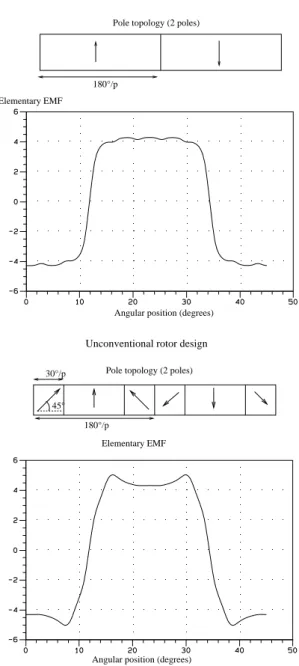
In this paper 2 kinds of rotor design are presented. The first one is the classical structure with a radial magnet over all the pole pitch. In the second one each pole is made of 3 magnets which are magnetized in unconventional magnetization directions. In both cases the magnets are stuck on the surface of the iron rotor core. The second kind of rotor can be easily made with bonded isotropic Rare earth magnets. Both rotors structures are shown in fig. 3. In the second configuration the widths and orientations of the magnets have been chosen in order to maximize the 1st and 3rd harmonics and to minimize the 7th, 9th and 11th harmonics of the elementary EMF. In figure 3 the waveforms of the elementary EMF for the 2 kinds of design are shown. The corresponding harmonic magnitudes amplitude are presented in table 4.
Table 4: EMF harmonic magnitudes
Elementary EMF Pole topology (2 poles)
45° 180°/p 30°/p
Angular position (degrees) Pole topology (2 poles)
180°/p Elementary EMF
Angular position (degrees)
Unconventional rotor design Conventional rotor design
Fig.3: Elementary EMF waveform for the 2 rotor design
5.2 Results
The first kind of structure considered is a conventional radial rotor with a sinusoidal current supply. In a second approach this classical machine is supplied using the strategy presented at paragraph 3.1. The required current level (first harmonic and third harmonic), the corresponding Joule losses and torque ripple are given in the first line of Table 4. The third EMF harmonic of this machine is around 25% of the first one. So with the strategy defined in part 3.1 the Joule losses have been reduced worth 5% for the same average torque (Table 5). We can also notice that for both cases the EM torque ripple is important. This phenomenon is due to the pulsating torques caused by the 7th and 9th harmonics of EMF.
Number of phases N = 5 Number of pole pairs P = 8 Stator core thickness Th = 6 mm Air gap e = 1 mm Angular teeth width Wt = 2.25 degrees Axial machine length L = 35 cm Bore Diameter D = 166 mm Slot depth Ds = 1 cm Total number of slot Ns = 80 (1slot/phase/pole) Number of conductors/slot 20
Slot fill factor 0.5 Statoric resistance Rs = 1.2 Ohms Required average torque 60N.m (100 to 500rpm) Power at 500rpm 3.1 kW Magnet total volume 1042 cm3 (almost 6 kg) Magnet material NeFeB Isotropic Bonded magnet Magnet Magnetization 0.6 T 1st harmonic 5,250 V 5,610 V 3rd harmonic 1,460 V 1,780 V 5th harmonic 0,697 V 0,530 V 7th harmonic 0,417 V 0,056 V 9th harmonic 0,295 V 0,024 V 11th harmonic 0,110 V 0,073 V Conventional design Unconventional design Rotor type
Next a second kind of rotor is considered. This unconventional machine is supplied using the strategy presented at paragraph 3.1. The corresponding Joule losses, currents value and EM torque ripple values are given also in Table 5. It is noted that the Joule losses have been reduced by about 20%. The EM torque ripples have also been widely reduced : the 7th and 9th harmonics of the EMF are very small, so the pulsating torques related to these harmonics has been reduced. So the presented unconventional structure of machine associated with a multi-machine feeding current strategy seems to be a very interesting solution in terms of minimization of the Joule losses and torque ripple.
Table 5: Results for a required torque of 60N.m
Fig.4: Global EM Torque for the 3 cases (60 N.m required)
4 Conclusion
In this paper several design configurations of Surface Mounted PM 5 phase motors fed by a PMW voltage inverter are studied using the association of a multi-machine modeling and a 2D Finite Difference field calculation software. This approach enables the determination of a design criterion to minimize the Joule’s losses for a given performance in terms of torque. For a given common set of parameters and a given performance specifications, some conventional and unconventional structures of rotor are compared. This study shows that the choice of unconventional rotor configurations can be a very interesting choice to improve performances of multiphase SMPM machines.
References:
[1] D. Gondouin, F. Menneron, “New diesel-electric propulsion system topologies ”, All Electrical
ShipAES 2000, 26-27 Oct. 2000 Paris, pp 66-71.
[2] P. Letellier, “ High Power Permanent magnet machines for electric propulsion drives ”, All Electrical
ShipAES 2000, 26-27 Oct. 2000 Paris, pp 126-132.
[3] S. Siala S., E. Guette, J. L. Pouliquen, “ Multi-inverter PWM control: a new generation drives for cruise ship electric propulsion”, European Power
Electronics Conference (EPE’2003) , September 2003,
Toulouse (France), CD-ROM
[4] A.C.Smith, S.Williamson, C.G.Hodge, « High Torque Dense Naval Propulsion Motors », IEEE
International Conference, IEMDC’03, Vol 3,1-4 June
2003,CD-ROM.
[5] C. Hodge, S. Williamson, S. Smith, « Direct Drive Marine Propulsion Motors », International
Congress on Electrical Machines (ICEM’02), August
2002, Brugges (Belgium), CD-ROM.
[6] H. Xu, H. A. Toliyat, L. J. Petersen, “Five-Phase Induction Motor Drives With DSP-Based Control System”, IEEE Transactions on Power Electronics, vol. 17 no 4, July 2002, pp. 524-533.
[7] P.T. Norton, P.E. Thompson, "The naval electric ship of today and tomorrow", All Electrical
Ship AES 2000, 26-27 october 2000 Paris, France, pp
80-86.
[8] Arkkio, N. Bianchi, S. Bolognani, T.Jokinen, F. Luise, M.Rosu, “Design of Synchronous PM Motor for Submersed Marine Propulsion Systems “, International
Congress on Electrical Machines (ICEM’02), August
2002, Brugges (Belgium), CD-ROM.
[9] R. Shi R., H. A. Toliyat, A. El-Antably, “Field Oriented Control of Five-phase Synchronous Reluctance Motor Drive with Flexible 3rd Harmonic Current Injection for High Specific Torque “, IEEE-IAS
annual meeting 2001, September/October 2001,
Chicago (USA), CD-ROM.
[10] Kestelyn X., Semail E., Hautier JP. “Vectorial Multi-machine modeling for a five phase machine”,
International Congress on Electrical Machines (ICEM’02), August 2002, Brugges (Belgium),
CD-ROM.
[11] E. Semail, A. Bouscayrol, J.P. Hautier, “Vectorial formalism for analysis and design of polyphase synchronous machines”, EPJ AP (European
Physical Journal-Applied Physics), vol. 22 no 3, June
2003, pp. 207-220.
[12] M. Lajoie-Mazenc, H. Hector, R. Carlson “procédé d’analyse des champs électrostatiques et magnétostatiques dans les structures planes et de révolution : programme DIFIMEDI”, Compumag’78, Grenoble France 4-6 sept. 1978
H1 only 63,0 W 4,3 N.m 3,25 A 0,00 A Rotor type Feeding current
strategy Joule losses EM torque ripple
Current first harmonic (RMS) Current third harmonic (RMS) Conventional (radial magnetization) Unconventional (3 magnets/pole) H1 and H3 (&3,1) 58,7 W 5,6 N.m 3,01 A 0,84 A H1 and H3 (&3,1) 50,3 W 1,2 N.m 2,76 A 0,88A