UNIVERSITÉ DE MONTRÉAL
CANTILEVER ARRAY PLATFORM FOR QUANTITATIVE BIOLOGICAL
ANALYSIS
BAHAREH GHOLAMZADEH AJEZ DÉPARTEMENT DE GÉNIE ÉLECTRIQUE ÉCOLE POLYTECHNIQUE DE MONTRÉAL
MÉMOIRE PRÉSENTÉ EN VUE DE L’OBTENTION DU DIPLÔME DE MAÎTRISE ÈS SCIENCES APPLIQUÉES
(GÉNIE ÉLECTRIQUE) AOÛT 2013
16.27 KHz
UNIVERSITÉ DE MONTRÉAL
ÉCOLE POLYTECHNIQUE DE MONTRÉAL
Ce mémoire intitulé:
CANTILEVER ARRAY PLATFORM FOR QUANTITATIVE BIOLOGICAL
ANALYSIS
Présenté par : GHOLAMZADEH AJEZ Bahareh
en vue de l’obtention du diplôme de : Maîtrise ès Sciences Appliquées a été dûment accepté par le jury d’examen constitué de :
M. SAVARIA Yvon, Ph.D., président
M. SAWAN Mohamad, Ph.D., membre et directeur de recherche
M. GHAFAR-ZADEH Ebrahim, Ph.D., membre et codirecteur de recherche M. ZHU Guchuan, Ph.D., membre
16.27 KHz
DEDICATION
16.27 KHz
ACKNOWLEDGMENT
I would like to express my sincere gratitude to my research directors Prof. Mohamad Sawan and Prof. Ebrahim Ghafar-Zadeh for their guidance and support during my graduate study. Also, I want to thank Prof. Yvon Savaria and Prof. Guchuan Zhu for accepting to evaluate this thesis. I would also like to thank Prof. Peter Grutter and Prof. Yoichi Miyahara in Physics department of McGill University for giving me the access to their laboratory in order to complete the mechanical characterization step of this project. Their suggestions and ideas helped me a lot in completing this thesis.
I am grateful to all the staff of Electrical engineering department of Polytechnique Montreal, specially Marie-Yannick Laplante, Laurent Mouden and Réjean Lepage for all their help and support.
I would also like to thank all my friends in Polystim neurotechnologies Laboratory, specially Ghazal Nabovati, Nicolas Laflamme-Mayer, Jérôme Le Lan, Guillaume Simard, and Sami Hached who were always there for me and made my study in Polytechnique one of the best experiences of my life.
My special thanks go to my family who are living far away, but their unconditional love and encouragement helped me a lot during the hard moments.
Finally I want to thank the Canada Research Chair on Smart Medical Devices for the financial support, and the CMC Microsystems for their service and support.
16.27 KHz
RÉSUMÉ
L'objectif de ce projet est de développer un réseau de microcapteurs pour collecter des données biologiques quantitatives. Ces types de données peuvent être utilisés dans divers domaines, notamment pour l'analyse cellulaire et moléculaire, la détection d’interactions biologiques spécifiques, la surveillance de maladies et la découverte de médicaments.
Les capteurs proposés possèdent des réseaux de « cantilevers » qui convertissent les interactions biologiques en variations mécaniques et électriques. Ces capteurs peuvent avoir une sensibilité élevée et ont montré leurs efficacités dans diverses applications. De plus, leur utilisation permet de concevoir un système à haut débit pour la détection en temps réel de diverses paramètres. Afin de développer ces capteurs, un logiciel multiphysique (COMSOL) a été utilisé pour modéliser les « cantilevers » et plusieurs simulations électromécaniques ont été réalisées pour atteindre une conception appropriée.
Deux méthodes de lecture, piezorésistive et capacitive, ont été choisies pour être utilisées avec les capteurs. Les deux capteurs ont été fabriqués par le biais de CMC Microsystems; le processus PolyMUMPs a été employé pour la fabrication de réseaux de capteurs capacitifs, et les capteurs piézorésistifs, quant à eux, ont été développés par le processus de MetalMUMPs. Enfin, les capteurs fabriqués ont été caractérisés suivant différentes étapes incluant l’interferometrie afin d'assurer leur fonctionnalité.
Sur la base des résultats de simulation et de caractérisation obtenus, ces capteurs peuvent être utilisés pour élaborer une plateforme haut débit à bas coût pour diverses applications biologiques.
16.27 KHz
ABSTRACT
The objective of the present project is to develop an array of microsensors for gathering cellular and molecular quantitative biological data. Such data can be used in various fields including cellular and molecular analysis, detection of specific biological interactions, monitoring diseases, and drug discovery.
The proposed sensing platform in this project can convert biological interactions into mechanical variations and subsequently converts the mechanical variations to electrical ones. This platform offers the advantage of high sensitivity, real time measurement, high throughput sensing array suitable for fundamental studies as well as clinical applications.
We modeled the operation of cantilevers using COMSOL multiphysics software. These simulation techniques can efficiently be used to choose the suitable design and dimensions of cantilevers. Two readout methods, piezoresistive and capacitive, have been chosen to be used along with sensors. Both sensors were fabricated through CMC Microsystems; PolyMUMPs process was employed for fabrication of capacitive sensor array and piezoresistive sensors were developed by MetalMUMPs process. The functionality of cantilevers and their incorporated sensors were characterized through different techniques including interferometry.
Based on these simulation and characterization results, the proposed sensors can be good candidate for developing a low cost, high throughput platform for various biological applications.
16.27 KHz
TABLE OF CONTENTS
DEDICATION ... III ACKNOWLEDGMENT ... IV RÉSUMÉ ... V ABSTRACT ... VI TABLE OF CONTENTS ...VII LIST OF TABLES ... IX LIST OF FIGURES ... X LIST OF SYMBOLES AND ABBREVISATIONS ... XIIIINTRODUCTION ... 1
CHAPITRE 1 FUNDAMENTALS OF CANTILEVER BIOSENSORS... 3
1.1 Modes of cantilever operation ... 5
1.2 Cantilever’s readout methods ... 7
1.2.1 Optical ... 8
1.2.2 Piezoresistive ... 9
1.2.3 Piezoelectric ... 12
1.2.4 Capacitive ... 13
1.3 Applications of cantilever biosensors ... 14
1.3.1 Label free detection of molecules ... 15
1.3.2 DNA analysis ... 19
1.3.3 Cell studies ... 22
CHAPITRE 2 PIEZORESISTIVE CANTILEVER ARRAY PLATFORM ... 26
2.1 Journal ARTICLE 1: A Cantilever Array Platform Dedicated to Quantitative Biological Analysis ... 26
16.27 KHz
2.1.1 Introduction ... 26
2.1.2 Cantilever design and implementation ... 29
2.1.3 Multiphysical modeling ... 32
2.1.4 Characterization of sensors ... 36
2.1.5 Discussion ... 39
2.1.6 Conclusion ... 40
2.1.7 Acknowledgment ... 41
CHAPITRE 3 CAPACITIVE CANTILEVER ARRAY PLATFORM ... 42
3.1 PolyMUMPs process ... 42
3.2 Simulations ... 45
3.3 Characterization and measurements ... 52
CHAPITRE 4 GENERAL DISCUSSION ... 57
CHAPITRE 5 CONCLUSION ... 61
REFERENCES ... 62
16.27 KHz
LIST OF TABLES
Table 1-1: Existing Cantilever sensor platforms ... 15
Table 2-1: Simulation parameters ... 32
Table 3-1: Simulation parameters ... 45
Table 3-2: Dimension of cantilevers on the chip ... 49
16.27 KHz
LIST OF FIGURES
Figure 1-1: AFM Cantilever (Image provided by Geiss and Hurley, NIST, Boulder, Colorado,
USA) [11] ... 3
Figure 1-2: Cantilever array platform with sensing and reference cantilevers [13] ... 4
Figure 1-3: (a) Static and (b) dynamic modes of cantilever ... 6
Figure 1-4: Optical detection for cantilevers ... 8
Figure 1-5: Wheatstone bridge ... 10
Figure 1-6: Differential measurement in cantilevers; sensor beams will deflect due to attachment of particles while reference beams will have no or very small deflection ... 11
Figure 1-7: Sensing platform for monitoring multiple cantilevers; VCSEL (Vertical cavity surface emitting lasers), PSD (Position sensitive detector) [40] ... 18
Figure 1-8: DNA structure ... 20
Figure 1-9: Attachment of cell to substrate through focal adhesions ... 23
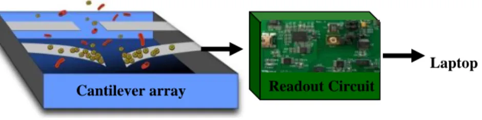
Figure 2-1: Illustration of the proposed cantilever array platform for quantitative biological analysis ... 28
Figure 2-2: Fabrication steps of cantilever sensors. (a) deposition of oxide layers, (b) oxide etching, (c) deposition of first layer of Silicon Nitride, (d) deposition of first layer of Polysilicon, (e) patterning of Polysilicon, (f) deposition of second layer of Silicon Nitride, (g) patterning of Silicon Nitride, (h) deposition of Anchor metal, (i) Final etching steps ... 30
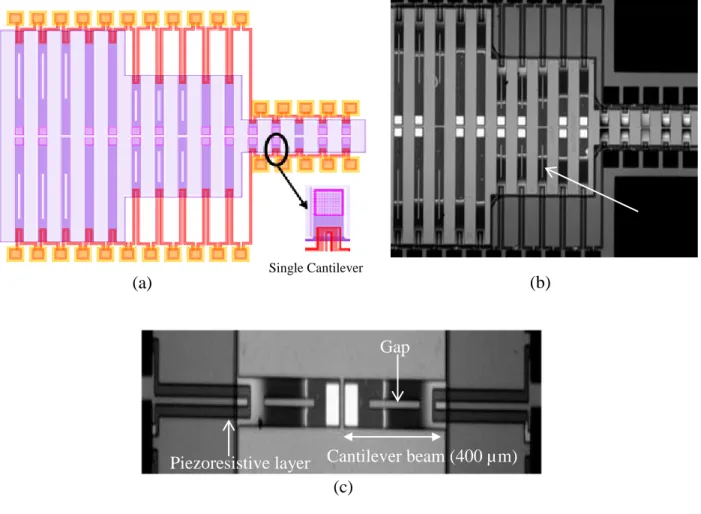
Figure 2-3: Piezoresistive sensor chip containing 30 cantilevers: (a) Schematic, (b) Microscopic image, (c) Zoomed image of two cantilever sensors ... 31
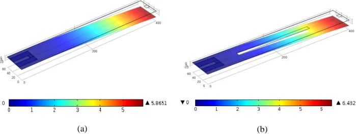
Figure 2-4: Displacement of cantilever sensors due to surface stress of 96 nN for rectangular cantilever beam, (a) without and (b) with the gap ... 33
Figure 2-5: Deflection of cantilever (L=100, 400, and 700 µm) versus applied forces ... 33
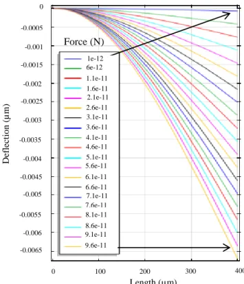
Figure 2-6: Displacement of sensor with length of 400 µm due to application of force in pico Newton range ... 34
16.27 KHz
Figure 2-7: Displacement of sensor with length of 700 µm due to application of force in pico
Newton range ... 34
Figure 2-8: Von Mises’s stress distribution (N/m2) on cantilever beam for 1 nN force ... 35
Figure 2-9: Variation of conductance for piezoresistive sensor (Length of cantilever=100 µm, Length of piezoresistive structure=20 µm) ... 36
Figure 2-10: Block diagram of resonance frequency measurement setup; LD (Laser diode), PD (Photo detector) ... 36
Figure 2-11: Interferometry setup for resonance frequency measurements ... 37
Figure 2-12: Frequency response of cantilever (Length=100 µm) ... 37
Figure 2-13: Comparison of resonance frequency ... 38
Figure 2-14: Electrical measurement setup ... 38
Figure 2-15: Piezoresistive sensing change due to applied mechanical force ... 39
Figure 2-16: Practical considerations (a) Stiction of long cantilevers, (b) Displacement of the pads, (c) Removal of Polysilicon layer, (d) fractured cantilevers ... 40
Figure 3-1: Structure of Capacitive sensor ... 42
Figure 3-2: Fabrication steps of cantilever sensors in PolyMUMPs process;(a) Deposition of first layer of Polysilicon (Poly0), (b) Patterning Poly0, (c) Oxide deposition and formation of dimple, (d) Patterning the oxide layer, (e) Deposition and patterning of second layer of Polysilicon (Poly1), (f) Removal of sacrificial layer ... 44
Figure 3-3: Layout of capacitive sensors ... 44
Figure 3-4: Fabricated sensors ... 45
Figure 3-5: Displacement of 50 µm beam for various ranges of force, (a) Micro Newton, (b) Nano Newton, (c) Pico Newton ... 46
Figure 3-6: Displacement of 100 µm beam for various ranges of force, (a) Micro Newton, (b) Nano Newton, (c) Pico Newton ... 47
16.27 KHz
Figure 3-8: Displacement of 200 µm beam for micro Newton forces ... 48
Figure 3-9: Distribution of electrical voltage (V) and Electric field (Arrows) on cross sectional plans for a beam with 50 µm length ... 49
Figure 3-10: Variation of capacitance for 50 µm beam due to various ranges of force, (a) Micro Newton, (b) Nano Newton, (c) Pico Newton ... 50
Figure 3-11: Variation of capacitance for 100 µm beam for various ranges of force, (a) Micro Newton, (b) Nano Newton, (c) Pico Newton ... 51
Figure 3-12: Interferometry setup ... 52
Figure 3-13: Resonance frequency measurements; (a) 50 µm beam, (b) 100 µm beam, (c) 300 µm beam, (d) 400 µm beam ... 54
Figure 3-14: Comparison of simulation and experimental results for resonance frequency ... 54
Figure 3-15: Setup for electrical measurements; (a) Capacitive to digital convertor board, (b) Wire bonded chip on PCB ... 55
Figure 3-16: Variation of capacitance due to application of force ... 55
Figure 4-1: Adhesion of the beams to the substrate due to stiction problem ... 57
Figure 4-2: Fracture of beams during the wire-bonding and tests ... 58
16.27 KHz
LIST OF SYMBOLES AND ABBREVISATIONS
α-hGH human Growth Hormone antibody AFM Atomic Force Microscopy
ASIC Application Specific Integrated Circuit CCD Charge Coupled Device
CMOS Complementary Metal Oxide Semiconductor CRP C-Reactive Proteins
DNA Deoxyribonucleic Acid E.Coli Escherichia Coli
GST Glutathione-S-Transferase HBsAg Hepatitis B surface antigen HbA1c Glycated hemoglobin
hGh human Growth Hormone
IgG Immunoglobulin G antibody
ISFET Ion Sensitive Field Effect Transistor
LD Laser Diode
MBM Molecular Biomechanical MEMS Microelectromechanical system
MOSFET Metal Oxide Semiconductor Field Effect Transistor MUMPs Multi User MEMS Processes
PCB Printed Circuit Board PD Photo Detector PDMS Polydimethylsiloxane PSA Prostate Specific Antigen
16.27 KHz
PSD Position Sensitive Detector PZT Lead Zirconate Titanate SIO2 Silicon Dioxide
SOI Silicon on Insulator ssDNA Single Strand DNA
TSMC Taiwan Semiconductor Manufacturing Company VCSEL Vertical Cavity Surface Emitting Laser
Zno Zink oxide
t Thickness L Length E Young modulus ρ density f Resonance Frequency ε0 Dielectric Constant εr Relative Permittivity F Force
A Effective area of Capacitor
d Distance between two plates of Capacitor
∆v Output Voltage of Wheatstone Bridge
Vi Applied Voltage to Wheatstone Bridge π1 Longitudinal Piezoresistive Coefficient
ξ Correction Factor
σ Stress
16.27 KHz ∆z Displacement of the cantilever beam
υ Poisson ratio
β Expansion Coefficient
λ Thermal Conductivity
P Total generated power
n Geometrical parameter w Width k Spring Constant C Capacitance R Resistance ∆ε Strain variation
INTRODUCTION
The optical methods are widely used in biological laboratories using labeling techniques. These methods require bulky and costly setup along with expensive chemical and biological reagents. Developing a system that gives us quantitative biological data and enables us to analyze the samples without using labeling methods can be useful for many applications. Such a system can be used in biological research, for instance to analyze several parameters like cell growth, extracellular matrix interactions, and DNA analysis. Hospitals and laboratories can also benefit from this device for various clinical purposes including the detection of cancer markers in patient’s sample.
Nowadays, considerable efforts are made for designing label-free techniques. However, most of these platforms contain small number of sensors, or they rely on using expensive measurement instruments. High throughput sensing platforms incorporated with appropriate readout systems can overcome these limitations and will be very useful for many life science applications. The primary step toward developing such a platform is the selection and modeling of sensors.
In order to propose a sensor for a biological analysis platform, different parameters should be taken into account. One of the first steps is to choose the type of sensor. Several studies have demonstrated the advantages of microelectromechanical systems (MEMS) for biological applications [1-3]. These devices are called BioMEMS. By using a large number of MEMS sensors in a platform it would be possible to monitor multiple parameters in real time. BioMEMS are implemented using different structures like micro-needles, membranes, cantilevers, plates, and etc. Among all the above-mentioned structures, cantilevers show a good potential for measuring various parameters with high sensitivity. Cantilevers are composed of a suspended beam that can convert biological interactions into mechanical and electrical variations. These sensors function based on the adhesion of cells or molecules on their top surface. Due to the variation in surface stress after adhesion, the beam will deflect and it is possible to relate the amount of deflection to the biological interaction that causes the displacement. One of advantages of the cantilever structure is that its fabrication is supported in several standard MEMS processes. Using a standard fabrication process makes it possible to develop many sensors at low cost. Another advantage of using cantilevers as sensors is that they have the potential to be integrated along with readout circuits on one chip.
16.27 KHz
Next step toward developing a sensing platform is to choose a suitable readout method for the detection of final output. Several methods can be used to measure the displacement of cantilevers among which optical, capacitive, piezoresistive, and piezoelectric readout are the most common techniques. Each of these methods has its own advantages and disadvantages. In order to select a good readout technique, one should consider various parameters including cost, portability, simplicity, and sensitivity.
Finally, in order to design an efficient system, it is important to model the sensors before the fabrication process and analyze the effect of different parameters on them. For modeling structures like cantilevers that deal with mechanical and electrical variations, it is essential to consider both physics in the modeling. Multiphysical simulations have already been used for several biological engineering applications and it has been shown that the results from these simulations can help in understanding the sensing process [4-5]. By considering all the relevant physics in modeling of cantilever sensors, it would be possible to reach a suitable design before starting the fabrication step.
In this project we have developed two arrays of cantilever sensors for quantitative biological analysis. Piezoresistive and capacitive techniques have been chosen as readout methods and the sensors have been modeled with COMSOL Multiphysics software. The multiphysical simulation methods enable us to create a link between electrical and mechanical characteristics of cantilever. Each array of sensors has been developed with a standard MEMS fabrication process through CMC Microsystems and several characterizations have been done to ensure their functionality. This thesis is organized in 5 chapters. In chapter 1, the fundamentals of cantilever biosensors will be introduced and different biological applications of these types of sensors will be presented. Chapter 2 contains the information regarding the first proposed sensor array that uses piezoresistive measurement for detection of displacement. The content of this chapter is submitted as journal paper to IEEE Sensors Journal. Chapter 3 focuses on the second proposed cantilever array using capacitive readout method following by the detailed information of simulation, fabrication and characterization processes. Chapter 4 discusses the challenges of developing these sensors along with practical considerations. Finally, the project will be concluded in chapter 5.
CHAPITRE 1
FUNDAMENTALS OF CANTILEVER BIOSENSORS
Nowadays developing small and inexpensive systems for monitoring various biological parameters is one of the growing demands in life science. Handheld devices have attracted the attention of researchers in both industrial and academic sectors to develop miniaturized biological analysis systems that have high sensitivity and can be used for drug discovery or for monitoring health conditions. One of the important steps in developing all these devices is the design of sensors. Several research groups are working on developing different types of micro scale sensors that can be used for various biological and medical applications. Among all different types of sensors, cantilevers have shown a good potential for biological studies. Cantilever is a beam which is fixed in one end and will deflect due to application of force on its surface. These sensors can have high sensitivity, good resolution and they can be fabricated with low-cost fabrication processes.
Originally, the idea of using a cantilever structure as a sensor emanated from atomic force microscopy (AFM) [6]. In AFM, a cantilever with a sharp tip is being used for measuring different parameters like the interactions between antibody-antigen [7-8], surface imaging [9] or manipulating small particles [10]. Figure 1-1 presents a common cantilever used in AFM [11]. In 1996, Butt reported one of the first applications of a single cantilever as a biosensor [12]. Since that time, many research groups become interested in using this structure for different chemical and biological measurements.
Figure 1-1: AFM Cantilever (Image provided by Geiss and Hurley, NIST, Boulder, Colorado, USA) [11]
16.27 KHz
Although single cantilever can have good performance in different applications, in order to have a high throughput system, it is necessary to increase the number of sensors. High throughput systems enable us to have several measurement points and they can be used in a variety of applications where multiple parameters or particles need to be detected simultaneously. In addition, by having more than one cantilever in a platform, it would be possible to calibrate and analyze the output based on a reference point. For example, in molecular detection applications, this reference point can be one of the cantilevers in the array which is exposed to the same environment, but it is not coated for binding with specific molecules. In this case, the signals from the coated beam will be compared with the reference cantilevers, thus it would be possible to remove the noise from the output and achieve more accurate measurements. Figure 1-2 presents a platform with sensing and reference electrodes.
Figure 1-2: Cantilever array platform with sensing and reference cantilevers [13]
In 1997, a group in Switzerland developed one of the first cantilever array platforms which was used for gas and vapor identification [14]. One of the primary projects that showed high potential of using cantilever array in biological studies was reported in 2000 by IBM-Zurich laboratory [15]. In their project, they developed a platform for DNA analysis and translated the variation of surface stress due to DNA hybridization and molecular binding into mechanical response of cantilever. Since then, all the researches which have been done in the domain of cantilever sensors demonstrated that sensor platform which consists of cantilever arrays can provide many advantages for various studies.
16.27 KHz
More recently, cantilever-based biosensors have been used for different biological applications including the detection of pH [16-17], label-free detection of molecules [18], monitoring temperature [19], DNA hybridization [15,20], interaction between antibody-antigen [21], etc. Usually in this type of sensors, application of force on top of the cantilever or variation of temperature or mass will displace the suspended beam and this displacement can be detected using different readout methods.
Cantilever biosensors are typically made from polymers, silicon, silicon nitride, or Polysilicon. However, in most biosensing applications, it is essential to cover the surface of the tip of cantilever with some specific layer of material. This process is known as the functionalization of cantilever sensors. The materials used to develop cantilevers depend on the application. For example, if the sensor is employed for detection of antigen, this layer can be a special type of antibody [22]. Sometimes a microfluidic structure should also be integrated with cantilevers in order to prepare the samples prior to the sensing step [23].
Cantilevers can be categorized in different groups based on several factors like their readout method and their operational mode. In the following sections of this chapter, further discussions and detailed information regarding each of these groups will be provided and then different reported applications of cantilever biosensors will be discussed.
1.1 Modes of cantilever operation
In general, when a cantilever operates as a sensor, two signals can be monitored. These two signals are the displacement (or bending of beam), and the change in the resonance frequency response. Cantilever’s operation can be categorized based on the type of variation used in the sensing process. Three modes defined for operation of cantilevers are static, dynamic, and heat modes.
In the static mode (figure 1-3 (a)), variation of surface stress will cause static bending of the beam. This surface stress variation is usually due to the attachment of target substances on the surface of cantilevers. Several studies have used cantilevers in this mode for sensing. For example Weeks et al used cantilevers in static mode as a pathogen detector with high sensitivity [24] and Pei et al presented a glucose biosensing system based on using cantilevers in this mode [25]. In static mode, the direction of bending depends on the type of the force being applied on
16.27 KHz
the surface. If the tensile stress is applied on top of the cantilevers, the beam will have upward bending and compressive stress will bend the beam toward down side [26-27].
Cantilevers used as biosensors can also operate in the dynamic mode (figure 1-3 (b)). This mode is usually used for monitoring mass variations; however any changes in surface stress can also be detected in this mode.
With biosensor cantilevers in the dynamic mode a shift of their resonance frequency is detected. When cantilevers are used in the dynamic mode, the beam will be excited externally at its resonance frequency and due to variation of the mass of the sensing target on its surface (e.g. due to attachment of particles) the resonance frequency will change. The relation between resonance frequency and mass can be described by the following equation [28]:
∆𝑚 = 𝑘(4𝑛𝜋2)−1(𝑓
1−2− 𝑓0−2) (1.1)
In equation 1.1, resonance frequency before and during the sensing process is defined by f0 and f1
respectively, k represent spring constant of the cantilever, ∆m is change in mass, and n is a geometrical factor.
Different studies have shown that by monitoring the variation of resonance frequency it would be possible to gather data about specific attached particles. For example, Detzel et al used variation of cantilever’s resonance frequency for assessment of E.Coli [29] and Hwang et al also used a cantilever in resonance mode for analyzing prostate-specific antigen (PSA) [21].
Dynamic cantilevers are usually not suitable for application in which the sensors should be put in aqueous environment. This is because the damping effect in solution can affect cantilever’s resonance frequency. In this case, in order to have a sensing system with high resolution, it might be essential to have a very complicated readout setup [30].
(a) (b) Figure 1-3: (a) Static and (b) dynamic modes of cantilever
16.27 KHz
The third mode for operation of cantilevers is called bimetallic or heat mode [30-31]. In heat mode, deflection of cantilever is due to bimorph effect. Cantilevers which are used in this mode can be fabricated by two layers of material with different thermal expansion coefficient factors. Usually in these types of cantilevers, one layer is metal and the other is silicon. By varying the temperature, the difference in the expansion coefficient result in deflection of the beam and it would be possible to detect small changes in temperature with high sensitivity.
In chemical and biological studies, the variation of temperature can be due to some reactions which are happening in the sample or it can be a part of characteristics of the material which is being sensed. For example, Berger et al used this type of cantilever as a calorimeter [32] and Gimzewski et al used a bimetallic cantilever for observing chemical reactions [33].
Equation 1.2 shows the relation between the bending of bimetallic beam as the function of the properties of materials which are used in the fabrication of cantilever [30]:
∆𝑧 =54(𝛽1− 𝛽2)𝑡1+𝑡2
𝑡22𝑘
𝑙3
(𝜆1𝑡1+𝜆2𝑡2)𝑤𝑃 (1.2)
In equation 1.2, ∆z is the deflection of the cantilever, β1, β2, λ1, and λ2 represent the expansion
coefficients, and thermal conductivities of two layers of materials respectively, t1, t2 are the
thicknesses of the layers, w is the width of the beam, P is the total generated power on the cantilever, and n is a parameter related to the geometry of beam.
1.2 Cantilever’s readout methods
Several methods can be used for detecting the deflection of cantilever. It is possible to categorize all these methods into two main groups- electrical and optical methods. Electrical methods convert the deflection of cantilevers into a change of electrical signals. The main readout techniques associated with cantilever structures are piezoresistive, piezoelectric and capacitive. On the other hand, for the cantilever systems in which detection is based on optical methods, the displacement of cantilevers will be monitored by using optical equipment.
Each of these techniques has advantages and disadvantages. In order to choose the best technique, one should consider different parameters like sensing environment, required resolution, dimensions of cantilever, minimum and maximum estimated deflection, etc. In the
16.27 KHz
Detector Laser Source
following sections, principles of detection based on each of these techniques will be presented and the advantages and disadvantages will be discussed.
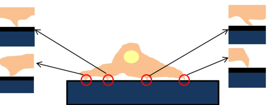
1.2.1 Optical
Optical readout technique was first introduced in 1988 [34]. Optical sensors usually work based on emitting light to the surface of cantilever with a laser and analyzing the position of reflected light to measure the beam displacement. Figure 1-4 illustrates the optical readout method.
Figure 1-4: Optical detection for cantilevers
Cantilevers that use optical readout are covered with reflective layers like metals and they follow a mechanical relation between deflection and the applied force that can be described by the Stoney formula [35]:
∆𝑧 = 3∆𝜎(1 − 𝜐) (𝐿𝑡)2/𝐸 (1.3) In equation 1.3, ∆σ is the surface stress, υ is the Poisson ratio, E is the Young modulus, and L and
t are the length and thickness of the cantilever respectively.
Optical systems have high sensitivity but require high complexity setup. In addition, whole optical readout setup is usually very bulky and it might not be suitable for handheld devices. However, some methods have been proposed to integrate the optical setup in a small space. For example, in 2006 a group proposed the integration of an optical readout method [36]. In that project, the cantilever was employed as a waveguide and its output light was being monitored. Another disadvantage of optical readout is the complexity of laser alignment. Usually, in most optical readout setups, the laser should be precisely focused on the tip of the cantilever and the alignment process can be very time consuming and costly. Moreover, optical sensors suffer from
16.27 KHz
limitations related to the environment where the sensing is performed. If the sensor is used in a liquid environment, refraction can affect the final output read by an optical system [37].
In addition, optical readout is not suitable for reading large array of sensors and it requires a time consuming and difficult process. Usually in order to use optical readout for a high throughput platform containing N sensors, there should be the same number of light sources and detectors in order to detect the variation of all cantilevers.
However, some studies proposed using multiplexing method to reduce the number of sources and detectors [14,38-39]. For example in 2002 a group developed a system for monitoring 8 cantilevers [40]. This setup consists of 8 VCSELs (Vertical-cavity surface-emitting laser) and one photo detector. Also it is possible to use one CCD (Charge coupled device) image screen as a detector for all sensors. For example, Yue et al used one collimated beam as a light source for hundreds of cantilever and detect their variation with a CCD plane [41].
Besides having high sensitivity and good resolution, another advantage of optical readout is the simplicity of the fabrication process for sensors which are going to be used with an optical setup. Because there is no need to integrate electronic structures in the sensor, the fabrication process is simpler in comparison with other sensors and it needs fewer fabrication steps. However, since detection in these sensors will be done based on light’s reflection from a surface, it is important to have a uniform surface to avoid light scattering [42].
1.2.2 Piezoresistive
Piezoresistive cantilever biosensors can measure surface stress variations which is usually due to the attachment of specific molecules on top of a cantilever beam. In this type of sensors, a piezoresistor is incorporated on the cantilever and the displacement of the beam will change its bulk resistance. Usually, the piezoresistive layer should be placed at a highly stressed point of the beam, close to the fixed end of the cantilever. For a simple rectangular beam, maximum stress (σMax) can be expressed by equation 1.4 [43]:
𝜎𝑀𝑎𝑥 =3𝐸𝑡2𝐿2∆𝑧 (1.4)
In this case, the resistance variation is demonstrated in [43]:
16.27 KHz
In equation 1.5, π1 is the longitudinal piezoresistive coefficient, and ξ is a correction factor
between 0 and 1.
Usually, a Wheatstone bridge circuit is used to monitor the output of piezoresistive cantilever sensors. As can be seen in figure 1-5, this circuit contains four resistors and the variation of their resistance will affect the output voltage.
Figure 1-5: Wheatstone bridge
The relationship between the output voltage variation (∆v), the applied voltage (Vi), and the
resistance can be explained by equation 1.6 [44]: ∆𝑣 = 𝑅1𝑅3−𝑅2𝑅4
(𝑅1+𝑅2)(𝑅3+𝑅4)𝑉𝑖 (1.6)
Assuming the resistance on the cantilever is one of the resistors, and keeping the other 3 at the same value we will have [44]:
𝑅1 = 𝑅 + ∆𝑅 (1.7) 𝑅2 = 𝑅3 = 𝑅4 = 𝑅 (1.8)
∆𝑣 =2𝑅∆𝑅+∆𝑅(2𝑅+∆𝑅)22𝑅 (1.9) And since usually the resistance variation is very small compared to R, we can estimate that [44]:
∆𝑣 =∆𝑅2𝑅𝑉𝑖 (1.10) Therefore, as shown in equations 1.10, it would be possible to follow the variation of resistance by monitoring the output voltage of Wheatstone bridge.
R1 R2 R3 R4 ∆v Vi
16.27 KHz
Piezoresistive cantilevers are good candidates for high throughput applications. Since there is no need for bulky, expensive optical equipment, it is possible to integrate sensor and readout circuit in the same chip. Therefore, using the piezoresistive cantilever concept, it is possible to design an inexpensive handheld device with hundreds of sensors.
However there are some disadvantages in using cantilevers based on the piezoresistive method. The most important drawback of this type of sensors is their low resolution compared to optical sensors. In addition, the output signal of these sensors depends on temperature variations [45]. Also since the current will pass through piezoresistive layer, there will be heat dissipation and thermal drifts in the sensor [46].
In order to solve these issues, several studies suggest a reference cantilever in the sensing platform [42]. This technique can decrease the effect of environmental changes and noise. In this case, one functionalized cantilever will act as a sensor and the other which is not functionalized will be placed in the same sensing environment and act as a reference. By performing the differential measurement based on two cantilevers, it will be possible to increase the sensitivity and the accuracy of the sensing system. Figure 1-6 presents an illustration of the differential measurement technique.
Figure 1-6: Differential measurement in cantilevers; sensor beams will deflect due to attachment of particles while reference beams will have no or very small deflection
One of the challenges in piezoresistive cantilevers is the complexity of their fabrication process compared to optical sensors. Usually in the fabrication of these sensors, some extra steps should be applied in order to deposit the piezoresistive layer embedded in between two insulator materials in order to avoid the contact between the sample solution and the electrical active components. In general, packaging complexity is another drawback of these sensors. Since in
16.27 KHz
biological applications, sensors are usually immersed in the solution, it is important to have a suitable package to cover all the electrical connections.
Another challenging issue for piezoresistive cantilevers is to search for a suitable method or material to increase their sensitivity. Among many proposed methods, it has been shown that is possible to use materials with low Young modulus to increase sensitivity [37]. In addition, the advantages of adding stress concentration regions into cantilever structures have been demonstrated in some studies [47]. In order to increase the stress in specific regions, some holes can be incorporated in the beam and simulations demonstrated that the number and shape of these holes can improve the output signal of cantilevers [47].
Unlike optical sensors, piezoresistive cantilevers are not limited by the sensing environment, and it is possible to do the measurement in an opaque media. Also, compared to optical sensors, the calibration step is usually very easy and it can be done automatically on a chip.
1.2.3 Piezoelectric
Like piezoresistive cantilevers, in piezoelectric sensors, mechanical variations will be translated into electrical signals. Generally when piezoelectric materials are under stress, voltage will develop across their boundaries and conversely, when a voltage is applied to them, they will deform. The piezoelectric effect was first discovered in the 1880s and since then it has been used in many different applications [48]. For example Hwang et al used this type of sensors for quantitative analysis of prostate specific antigen (PSA) [21], and McGovern et al developed a piezoelectric cantilever platform for label free detection of Bacillus anthracis [49].
In piezoelectric cantilevers, the sensing and actuating structure can be incorporated on the beam by depositing a piezoelectric material like Lead Zirconate Titanate (PZT) and Zink Oxide (ZnO) [50]. In these sensors, attachment of target substances on the cantilever will result into variation of resonance frequency. Equation 1.11 can be used to describe the relation between the resonance frequency and the cantilever characteristics [51]:
𝑓 = 0.162(𝐿𝑡2)√𝐸𝜌 (1.11)
where t and L are the thickness and length of cantilevers respectively, E is its Young modulus, and ρ is the density. Piezoelectric sensors can be used in the development of high throughput
16.27 KHz
systems and they have no limitations regarding the sensing environments. For example, unlike other sensors, piezoelectric cantilevers can operate in liquids and damp environments [52]. One of the disadvantages of both piezoresistive and piezoelectric sensors is the dependency of their output on the variation of temperature [45]. In addition, since these sensors also need electrical connections, it is important to follow a suitable protocol for their packaging.
Another drawback of this type of sensors is that the piezoelectric structure requires a thick layer of material in order to generate signal with appropriate amplitude. Having a thick layer of material will decrease the mechanical variation of the beam and consequently decrease the sensitivity [47]. Also, usually piezoelectric sensors are not efficient for low frequency applications or in situations when the variation of the cantilever position is very slow [53].
1.2.4 Capacitive
Capacitive sensors can be used to detect different variables like pressure and conductivity. Any parameters which affect the value of capacitance can be measured by capacitive sensors. In general, capacitance is equal to the division of the charge by the applied voltage between two conductive plates, and it can also be defined by equation 1.12:
𝐶 = 𝜀0𝜀𝑟𝐴𝑑 (1.12)
where ε0 and εr are the dielectric constant and relative permittivity of the material between the
plates respectively, A is the effective area and d is the distance between two plates. Different applications of capacitive sensors are based on changes of one of these parameters.
One of the main methods which is often used in capacitive cantilever sensors is to exploit the variation of the space between two electrodes. In this case, the beam will act as one electrode and the second electrode will be a fixed plate, which is placed underneath the beam. Since this variation has a direct effect on capacitance, cantilevers can detect very small forces that can make minute deflections.
Different studies have shown that the output signal of MEMS capacitive sensors is stable and independent of temperature variations [54-56]. This is one of the important advantages of capacitive sensors compared to piezo cantilevers. Another advantage of capacitive cantilevers compared to other electrical methods is their low-power consumption [54].
16.27 KHz
It is important to note that capacitive sensors cannot be used in applications requiring a large distance between the beam and bottom electrode. The reason is that usually the distance between two electrodes is very small and the deflection will be limited by this space. Another drawback of capacitive cantilevers is their low sensitivity compared to optical sensors [57].
The capacitive sensor based platforms can be used in high throughput applications when it is essential to monitor arrays of sensors. Up to now capacitive sensors have been used in various fields. For example, in 1992, Brugger et al used these types of sensors as atomic force microprobe with integrated readout circuits [58]. Also several capacitive cantilever platforms have been developed for mass detection with high sensitivity [59-60]. In recent years some systems based on capacitive sensors have been proposed for different biological applications. One of the new proposed platforms is introduced in 2013 by Sangeetha et al for Tuberculosis detection [61].
It should be noted that there is one major drawback in the cantilever platform using capacitive sensors and it is the generation of faradic currents between two plates when the solution is an electrolyte [57]. In addition, the packaging and encapsulation of electrical connections is another practical issue when the sensors are used in a liquid environment. These characteristics, limit the application of cantilever sensors operating in the capacitive mode.
1.3 Applications of cantilever biosensors
Until now, cantilever sensors have been employed in several biological domains including DNA studies [62-65], drug discovery [66], cellular analysis [67-68], and biomarker detection [69-71]. Results from many projects which use cantilever platforms have shown that these sensors can demonstrate good sensitivity and high resolution.
Some of the developed systems based on the single cantilever or an array of cantilevers have been demonstrated in table 1-1. As it can be seen in this table, cantilevers with different readout techniques have been used for various applications.
16.27 KHz
Table 1-1: Existing Cantilever sensor platforms
In the following sections, three applications in which cantilevers have been proved to be useful will be discussed.
1.3.1 Label free detection of molecules
Cantilever sensors have been widely used for studying antibody-antigen interactions and/or for detection of different molecules in an analyte. These sensors enabled diagnosing different diseases and following up the treatments process. The most important advantages of cantilevers for these applications is that they are using label free techniques. Labeling is the most common approach which is being used for biological analysis. In this method, special chemical particles called probe molecules can be put in contact with samples. These particles can attach to molecules of interest, interact with them, and exhibit different behaviors after attachment. This difference can be in v a r i o u s forms include variation of color, emission of radioactive waves or light which can be detected with special equipment. Although labeling method can have good sensitivity, but it is usually very costly and time consuming [85]. Moreover, this method needs to be practiced by experienced persons in special facilities like hospitals,
Application Readout
method
Ref
Water molecular adsorption piezoresistive [72]
Biochemical sensing piezoresistive [73]
Antibody-based protein detection piezoresistive [74]
Continuous label free detection of cardiac biomarker proteins optical [40]
Biochemical sensor piezoresistive [75]
Enzymatic detection optical [76]
Real time detection of Liposome piezoresistive [77]
Intermolecular force measurement Piezoresistive [78]
Detection of label-free disease marker proteins piezoresistive [18]
Glucose sensing optical [79]
Consolidated bioprocess monitoring (simultaneous Glucose and Ethanol detection)
piezoresistive [80]
Pathogen detection (salmonella enterica) optical [24]
Detection of specific carbohydrate-protein interaction with Pico molar sensitivity
optical [81]
Multiple label-free bio detection and quantitative DNA-binding assay
optical [26]
Immunoassay of prostate-specific antigen Piezoelectric [82]
Label free protein recognition optical [83]
16.27 KHz
laboratories or clinics. Developing a platform based on cantilever sensors will reduce the cost and time of experiments and it can eliminate the risk of alteration of molecules during the labeling process [86]. One of the most common applications of cantilevers in this domain is the detection of specific biomarkers (e.g. cancer). Several groups have proposed different systems that can be used for screening and early stage diagnosis of different types of cancers. In these types of applications, specific antibody or antigen will be immobilized on the surface of beam and when the sensors are put in the sample, the target molecules will be attached to the immobilized layer and cause a deformation in the cantilevers.
Both optical and electrical readout methods have been used for developing systems for label free detection of molecules. For example, Zhou et al presented a piezoresistive cantilevers for the detection of P53 antibody which is a cancer biomarker [87]. Based on several studies, P53 gene is involved in different types of cancers including breast, lung, ovarian, prostate, and melanoma therefore having a platform which can detect this gene in a sample or monitor its level during a treatment can be very beneficial. In their platform, they have fabricated piezoresistive cantilevers with thickness of 650 nm. Usually piezoresistive cantilevers are fabricated by polycrystalline silicon. However, in their system, instead of using polycrystalline silicon, they have used single crystalline silicon layer of SOI (Silicon On Insulator) wafer for their piezoresistive structure to improve the sensitivity. In this platform, they have employed a differential measurement technique and the output was being monitored by a Wheatstone bridge. Based on their results, they were able to detect antibody in the range of 20 ng/ml to 20 µg/ml and they have monitored surface stress variation up to 0.12 N/m for this range of antibody concentration [87].
Another platform based on piezoresistive cantilever array is presented by Dauksaite et al who used this system for the detection of Glutathione-S-transferase (GST) [74]. They have used Cantion-NanoNord A/S nanomechanical cantilever technology platform that consists of four cantilevers (CantiChip4) and its readout system (CantiLab). The length, width and thickness of cantilevers were 120 µm, 50 µm and 480 nm respectively. During their experiments, GST antibodies were immobilized on the beam and the results showed that the system was able to detect 40 nM of GST protein with an average signal of 4-5 µV in a differential measurement scheme [74]. Wee et al also developed a piezoresistive sensor and they tested that sensor for the detection of C-reactive proteins (CRP) and prostate specific antigen (PSA), which are markers of cardiac disease and prostate cancer respectively [18]. They have fabricated their sensors and used
16.27 KHz
PDMS and polycarbonate to create a microfluidic structure for performing the biological tests. They have also employed Wheatstone bridge and differential measurement for reading the output signal.
In another project, Lee et al presented a system for the detection of PSA [82]. They have used PZT (Lead Zirconate Titanate) cantilever in their system and monitor the deflection of cantilever due to interaction between immobilized PSA antibody and PSA by using piezoelectric effect. The detection is being performed by monitoring the shift in resonance frequency and they have done their experiments with 2 different dimensions of cantilever beam (300 µm×100 µm×2.26 µm and 150 µm×50 µm×2.26 µm). Using different dimensions enabled them to observe the effect of beam dimension on minimum detectable sensitivity. They have reported an increase in resonance frequency change for smaller cantilever which indicates an increase in minimum detectable sensitivity and they proposed that this change might be also due to the smaller interaction area on these cantilevers. Their experimental results showed sensitivity as low as 10 pg/ml [82].
Another system that used piezoelectric method for antibody-antigen studies is presented by Lee et al [88]. They have a piezoelectric cantilever platform for measuring the concentration of Hepatitis B surface antigen (HBsAg). HBsAg is a part of surface of Hepatitis B virus and is being used as a biomarker for the detection of Hepatitis B infection. They have also employed PZT as their piezoelectric layer and they used standard micromachining process for fabrication of sensors. In their platform, monitoring the variation in resonance frequency was done with a computer based measurement device. By immobilizing anti-HBsAg on their cantilever and observing the resonance frequency shifts they were able to detect mass of HBsAg in range of 0.1-100 ng/ml [88].
In addition to silicon based cantilevers, several sensors have been developed by using polymer materials. SU-8 is one of the polymers which is commonly being used for cantilever fabrication and its low Young modulus makes it possible to design sensors with high sensitivity. Calleja et al are one of the groups that used SU-8 for their sensor fabrication [89]. Their system is based on single SU-8 cantilever and optical readout and they have used it for monitoring the interaction between human growth hormone (hGH) and its antibody (α-hGH). Based on their presented results, they were able to detect surface stress as low as 1 mN/m with their platform. In their project, they compared the results of polymer based cantilevers with silicon nitride beam coated
16.27 KHz
with gold layer and they showed that using polymer for fabrication of cantilevers will eliminate the environmental limitations which usually exist in silicon based sensors like the dependency on pH variations [89].
Although the detection of a single antibody or antigen might provide informative data, however in practice it might be essential to detect the concentration of various target molecules (e.g. antibody/antigen). By taking advantage of multifunctional measurements using cantilever arrays, Arntz et al developed a platform enabling the detection of 7 different antibody-antigens [40]. They used an optical method for detecting the displacement of the beam. Although the optical method often limits the number of sensor array and makes readout a complicated task, it enabled high accuracy measurement (0.1 nm). Dimensions of their beams were 500 µm×100 µm×500 nm and the pitch between them was 250 µm. They have performed the experiment for detection of Creatin kinase, and Myoglobin which are cardiac biomarker proteins. In order to decrease the effect of thermal drift and other undesirable effects of the sensing environment, they have used differential measurement and based on their report they were able to reach sensitivity below 20 µg/ml for myoglobin detection [40]. Figure 1-7 presents the platform that they have used in their studies.
Figure 1-7: Sensing platform for monitoring multiple cantilevers; VCSEL (Vertical cavity surface emitting lasers), PSD (Position sensitive detector) [40]
Another platform that utilized high accuracy optical readout technique is presented by Sharma et al [90]. This group has developed a cantilever platform for detection of diabetic marker called Glycated hemoglobin (HbA1c). The detection level of HbA1c is very important for the diagnosis of diabetes as part of its treatment modalities. Usually the methods used for detecting HbA1c are chromatography, electrophoresis, colorimetric, spectroscopic, etc. But these methods are normally time consuming and expensive. In their system, they have utilized commercialized
16.27 KHz
cantilever with dimensions of 500 µm×100 µm×1 µm and they used optical system with accuracy of 0.1 nm for detection of cantilever deflection. By using this platform they were able to reach a dynamic range of sensitivity located between 0.147 pM and 1.47 pM [90].
1.3.2 DNA analysis
Another application of cantilever biosensors is in field of DNA analysis. DNA (Deoxyribonucleic acid) is a macromolecule which carries genetic information of living creatures. DNA analysis plays an important role in variety of biological process such as detection of genetic diseases. In fact, DNA analysis can result into detection of new treatments for different diseases or discovery of the fundamental problems in living organisms.
DNA molecules are usually in the form of double helix which is composed of two long strands of nucleotides and each nucleotide has sub units of sugar, phosphate and nitrogenous bases. The strands are made by formation of the bond between sugar and phosphate of each two different nucleotides and two strands are linked together by hydrogen bonds between bases of two nucleotides. Melting process will result into separation of two strands of DNA and formation of ssDNA (Single strand DNA). Melting can occur in specific situations with high temperature, low salt, and high pH [91].
Usually DNA analysis is performed by using optical equipment and using labeling methods. DNA detection can also be performed by using ISFET transistors; however its accuracy of detection is influenced by pH value and temperature [92].
Several studies reported that cantilever biosensors can be a good candidate for DNA analysis. In these applications, in order to detect specific single strand DNA (ssDNA) in a solution, the hybridization process is often used. During the hybridization process, each single strand of DNA will be hybridized with its complementary pair. DNA hybridization can be useful for monitoring different gene expressions. In addition, the hybridization process can be used for screening of specific target molecules in a sample, monitoring a specific diseases and assessing steps of a treatment.
For this process, the surface of a beam is coated with special ssDNA probe and these probes will hybridize with their complementary ssDNA in the solution. Usually coating of the surface will be done by covering the beam with a layer of gold and using thiol linker at the end of ssDNA [93].
16.27 KHz
Different papers have shown that ssDNA adsorption on cantilever will result into the variation of surface stress around 30-50 mN/m [94]. Several experiments have shown that only the presence of complementary strand will result into deformation of cantilever and uncomplimentary ones will not have effect on the beam displacement [95-98] and it is because of the strong bond which will be formed between the complementary strand and the probe molecule on top of the cantilever.
Another application of this type of cantilever-based biosensors is the detection of DNA mutation which is responsible for several types of diseases. During mutation a change will happen in nitrogen base of DNA. Four types of nitrogen bases in nucleotides are Adenine (A), Thymine (T), Guanine (G), and Cytosine (C). As mentioned previously, there is a link between nitrogen bases in DNA. In this link, Adenine always paired with Thymine, and Guanine and Cytosine are always connected together. Figure 1-8 demonstrates the structure of DNA.
Figure 1-8: DNA structure
Some of the changes that can cause mutation are variations of the base, insertion of extra base pairs in DNA sequence, or loss of one or more of the bases. Some mutations might not have high impact on the whole living organism, but the others might lead into severe malfunction of proteins and cells. Mutation can result into genetic disorder and can cause disorders like anemia [99], and hemophilia [100-101]. Diseases like cancer can also result from series of mutations [102-105].
Many groups propose cantilever-based platform for performing DNA studies on mutations. For example, Hansen et al developed a cantilever-based system for detecting DNA single-Nucleotide mismatches [106]. In their platform, they used optical method for the detection of cantilever
Adenine Thymine
Guanine
16.27 KHz
deflection which was caused by hybridization on surface of the beam. Based on their results, the deflection of cantilever in their experiments was in the nano meter range. In their study, they used triangular silicon AFM cantilever with length of 180 µm and they did the necessary surface functionalization for immobilization of probe DNA. Their label free platform can be used for monitoring and treatment of diseases, which are due to this type of mutation [106].
Also an optical cantilever made from SU-8 was developed by Calleja et al [107]. In order to increase the sensitivity of their sensors, they used the SU-8 polymer instead of silicon. Their experiments showed that sensitivity of their system is six times higher than commercial silicon nitride cantilevers. They employed cantilevers with different geometry (L=100, and 200 µm, W=20, 30, and 50 µm, t=1.3-2 µm) and their results showed nano meter deflection during the experiments. They have tested performance of the device by monitoring the adsorption of ss-DNA on the gold surface of the beams and reported that surface stress variations as small as 60 µN/m can be detected by SU-8 cantilevers [107]. Fritz et al also used an array of cantilevers with optical setup and showed that it is possible to detect single based mismatch between two 12-mer oligonucleotides (short ssDNA with 12 nucleotides) [15]. They have used a differential measurement technique in order to get very precise signals and their experimental results revealed that hybridization of 12-mer oligonucleotides can produce 5 mN/m compressive surface stress [15].
McKendry et al presented cantilever in array format to study DNA hybridization and detect DNA sequences [26]. They have used array of 8 cantilevers (L=500 µm, W=100 µm, t=1 µm) provided by IBM Zurich Research Laboratory and employed optical method for detecting displacement of the beams. Their experimental results showed that DNA hybridization produces average differential displacement signal of 9.8 nm which is equal to surface stress of 2.7×10⁻³ N/m. Yang et al are one of groups that used cantilevers with electrical readout method for hybridization detection [108]. Their experiments showed that for 3×10¹¹ ssDNA molecules on cantilever, surface stress will be 0.15 N/m. Their sensor which has been fabricated with CMOS technology has dimension of 125 µm×60 µm×0.75 µm with a Polysilicon layer incorporated as a piezoresistive material and its sensitivity was 3.5×10⁻⁵ m/N. In their platform, they employed bridge circuit for piezoresistive measurements and they used parallel sensing with reference electrode to avoid thermal noise. Another piezoresistive cantilever platform for DNA detection
16.27 KHz
application was proposed by Huang et al [109]. They have presented a fully integrated DNA detection platform which has been fabricated in 0.35 µm CMOS Bio-MEMS technology. Their whole die area was 30.4 mm2 and the dimension of cantilever beam was 180 µm×80 µm×1.5 µm. The difference between their system and other piezoresistive cantilever sensors was in their readout circuit. Since bridge circuit for piezoresistive measurements usually have offset problem, they chose a structure based on a ring type oscillator and convert the small resistance variation to frequency shifts. They have shown that there is 130 kHz frequency variation between matched and mismatched DNA samples and their detection range was between 100 pM to 1 µM [109]. Adami et al also developed a DNA detection platform that consists of array of piezoresistive sensors and a readout Application Specific Integrated Circuit (ASIC) which has been implemented in 0.35 µm CMOS technology [110]. They have built an array of very thin single crystal beams and used cantilevers in the static mode. In their paper, they have also compared the performance of two other types of piezoresistive cantilevers; SIO2 beam with Polysilicon
piezoresistor and SU-8 beam with gold strain gauge. Based on their report, although polymer cantilevers usually have better sensitivity because of their low elastic modulus but the performance of the sensor can be limited since gold strain gauge has high stiffness.
1.3.3 Cell studies
One of the hot research areas in this field is analyzing the interactions between cells and extracellular matrix or substrate which can be helpful in several biological domains like tissue engineering or characterizing disease like cancer and leukemia [111-115]. Also the data which can be gathered by this type of analysis will provide critical information on cell motility, migration and survival.
During the interaction between cells and extracellular matrix or substrate, special protein bonds so called focal adhesions are formed and cells can physically be connected to extracellular matrix or substrate through these bonds (Figure 1-9). These protein bonds will also provide a pathway for signaling. The force which will be applied on a substrate through these focal adhesions called traction force and it can be affected by different factors like stiffness of substrate and type of cells [116-120]. Having quantitative information about these types of forces can lead into new discoveries in different fields.
16.27 KHz
Figure 1-9: Attachment of cell to substrate through focal adhesions
Since cellular forces are very small, their measurement is a challenging task. Based on literature, the focal adhesion forces are in order of 10 nN [121-124]. Different structures and methods have been proposed for measurement of focal adhesion forces, understanding their formation and effect of their alteration on cell behaviour. The most common method which is being used for measurement of the traction force of cells is “traction force microscopy” [125-126]. This method involves using an elastic substrate that will deform due to the applied traction forces from cells and its deformation will be monitored by using imaging techniques. Some other systems which have been proposed for study of cell forces involve using micro-needles [127], micro pillar arrays [128] or thin membranes [129-131]. Another structure which has been proposed in 2010 by Klein et al is microstructure scaffold [132]. In addition to all these methods, cantilever platform can also be used for measurement of cellular forces. In 1997, a system composed of cantilevers and optical readout setup has been proposed by Galbraith and Sheetz and it was being used for monitoring the traction force during migration of chicken embryo fibroblast cell [133]. However, the system which was proposed by this group could only determine the force in one direction and was only measuring the force in specific locations.
Park et al also developed a system for real time measuring of contractile force of Cardiomyocytes which can be used in studying heart failure problems [134]. Cantilevers in this study were made from PDMS because of its low Young modulus and sensitivity to small amount of force. In addition, PDMS is a suitable material for biological applications since its transparency allow the use of optical techniques and it is nontoxic to cells. During their experiment, they have cultured Cardiomyocytes on the beams and displacement of the sensors has been monitored by optical method. Cantilevers had 20 µm thickness and they had been fabricated in 5 different widths (50,
16.27 KHz
100, 150, 200, and 300 µm). The length of each beam in all sensors was 5 times of its width. Sensitivity of sensors with length of 250, 500, and 750 µm was 6.97×10⁻⁴, 1.74×10⁻⁴, and
7.74×10⁻⁵ MPa/µm respectively. Based on their results, they were able to monitor variation of stress from cell in range of 2 to 5 nN/µm2 which is consistent with other types of measurements. The minimum detectable stress in this platform was 7.74×10⁻⁵ MPa/µm.
Another platform based on cantilever sensor was developed by Antonik et al for monitoring the variations in mechanical behaviour of living cells [135]. Their project was based on the known fact that several parameters can change characteristics of cells. These parameters can be a signal such as hormone that can cause movement in some cells or viral infection that can change cytoskeletal activity of a cell. Their platform can be used in different applications like drug screening, pollution or biological weapon detection. In addition, it can be considered as a platform for studying mechanical properties of a living cell which is an important step in several biological studies. During their experiments, they have grown Madine Darby Canine Kidney cells on a commercialized tipless V shaped AFM-type cantilever and used optical methods for detection of beam displacement. Each chamber, designed for doing the tests, could have one or two cantilevers as a sensor. After growth of cells on the beam, they have observed its deflection in presence of two toxic substances (lytic bee venom melittin, and respiratory inhibitor sodium azide).
Yin et al also proposed a system for probing single cancer cell mechanics [136]. Their device composed of microfluidic channel and an array of piezoresistive cantilevers and they have used microelectrodes for applying dielectrophoresis and trapping human breast adenocarcinoma on the beam. This device can be used for analyzing the mechanical process that controls the invasion of cancer cells. Based on one report which has been published in Biophysical journal in 2008, there is a relation between contractile force of a cancer cell and its invasiveness; and cancer cells might become more invasive by becoming more contractile [137-138]. Their device was fabricated in TSMC 0.35 µm and the microfluidic structure had been prepared by PDMS molding process. Also some post processing steps have been done in order to prepare cantilevers for biosensing applications. Cantilever dimensions in their platform were 50 µm×30 µm×2 µm and they have used Wheatstone bridge as their readout circuit.
![Figure 1-1: AFM Cantilever (Image provided by Geiss and Hurley, NIST, Boulder, Colorado, USA) [11]](https://thumb-eu.123doks.com/thumbv2/123doknet/2331551.31810/18.918.211.711.737.995/figure-cantilever-image-provided-geiss-hurley-boulder-colorado.webp)