HAL Id: hal-01663124
https://hal.archives-ouvertes.fr/hal-01663124
Submitted on 13 Dec 2017
HAL is a multi-disciplinary open access archive for the deposit and dissemination of sci-entific research documents, whether they are pub-lished or not. The documents may come from teaching and research institutions in France or abroad, or from public or private research centers.
L’archive ouverte pluridisciplinaire HAL, est destinée au dépôt et à la diffusion de documents scientifiques de niveau recherche, publiés ou non, émanant des établissements d’enseignement et de recherche français ou étrangers, des laboratoires publics ou privés.
A novel approach for global environmental performance
evaluation of electric batteries for hybrid vehicles
Julien Garcia, Dominique Millet, Pierre Tonnelier, Sophie Richet, Raphael
Chenouard
To cite this version:
Julien Garcia, Dominique Millet, Pierre Tonnelier, Sophie Richet, Raphael Chenouard. A novel approach for global environmental performance evaluation of electric batteries for hybrid vehicles. Journal of Cleaner Production, Elsevier, 2017, 156, pp.406 - 417. �10.1016/j.jclepro.2017.04.035�. �hal-01663124�
1/21
©2017. This manuscript version is made available under the CC-BY-NC-ND 4.0 license
http://creativecommons.org/licenses/by-nc-nd/4.0/ https://doi.org/10.1016/j.jclepro.2017.04.035 Words: 7835 + Annex I (279) = 8114
A novel approach for global environmental performance evaluation of electric batteries for hybrid vehicles
Julien Garcia1,2*, Dominique Millet3, Pierre Tonnelier1, Sophie Richet1, Raphael Chenouard4
1PSA Peugeot Citroën - Centre Technique de Vélizy, Route de Gisy, Parc Inovel Sud, 78943
Vélizy-Villacoublay Cedex
2Supméca, 3 rue Fernand Hainaut, 93400 Saint-Ouen, France
3Seatech, avenue de l'Université, BP 20132, 83957 La Garde Cedex, France
4Ecole Centrale de Nantes, 1 rue de la Noë, BP 92101, 44321 Nantes Cédex 3, France
*Corresponding author: julien.garcia1@mpsa.com
Abstract
The automotive product is increasingly restricted by environmental regulations, including reducing emissions of CO2 and pollutants in exhaust pipes of vehicles. One solution
implemented in the automotive industry are plug-in hybrid electric vehicles (PHEV) that use an electric traction battery. To help vehicle manufacturers in their choice of traction battery from an environmental point of view, a simulation method of environmental impacts generated by the use phase is proposed in this paper. This method takes into account the possible usages of the vehicle and potential developments of electric mix, with the formulation of a constraint satisfaction problem (CSP) solved using constraint programming (CP) techniques. The sensitivity of five parameters is investigated: the electricity mix used to charge the battery, the battery mass, electric consumptions, the autonomy in “all-electric mode”, and the share of total travel in “all-electric mode”. Power grid is the most differentiating parameter for global warming and PHEV generates less impact if less used in “all-electric mode” on a high carbon intensity power grid. Lastly, CSP acausal modeling makes it possible to process different simulations with the same model.
Keywords: environmental assessment; constraint modeling; automotive; Li-ion battery; use phase
1 Introduction
The transport sector is one of the main sources of carbon dioxide (CO2) emissions. To fight
against global warming, the European Union has regulated the passenger vehicle CO2 emission
2/21
Car makers have responded by seeking solutions to reduce vehicle fuel consumption, including the integration of lightweight materials (composite, aluminum), and the electrification of powertrains. The latter consists in substituting the thermal energy for electrical energy. This substitution can be partial: it is called hybrid vehicles (HEV - Hybrid Electric Vehicle) or hybrid electric plug-in (PHEV - Plug-in Hybrid Electric Vehicle). It can also be total: it is called electric vehicles (BEV - Battery Electric Vehicle). In both cases, it is necessary to be able to store electrical energy in the vehicle. To do so, the use of electric batteries is the current chosen solution of automakers.
In this paper, a methodological approach for the environmental assessment of traction batteries for PHEV or BEV is proposed. The overall objective is to guide design choices during the upstream phases of design in a car maker. However, during the innovation phase, the battery is not fully developed. In addition, the design of batteries is controlled by the battery manufacturers; the car maker defines the design specifications that match with the use he intends to make. The design specifications should answer to a specific use of the vehicle that is controlled by the car manufacturer. Currently, environmental evaluations of batteries are using discrete models of life cycle assessment (LCA): one LCA model parameterization gives one result. For more results, parameterization must be changed, so using LCA during the specification phase or the supplier selection phase would necessitate considerable time.
So an approach has been implemented that helps car makers to simulate the use of an electric battery in order to evaluate its environmental impact and to choose the appropriate battery for its adequate use. The approach is based on the development of a specific tool: EcoBatt. A special feature of this research is the Constraint Programming (CP) algorithms for solving constraint satisfaction problems (CSPs) representing the scenario of the use phase. CP and CSPs still found little use for solving ecodesign problems (Larroude et al., 2011; Tchertchian et al., 2013) whereas it is more widespread in preliminary design (Chenouard et al., 2009; Meyer and Yvars, 2012). CSPs in EcoBatt aim to use continuous models of LCA and to simulate multiple usage scenarios of several battery technologies. The purpose of this approach is to simulate the potential environmental impacts generated by multiple usage scenarios, and to deduct environmental optimization scenarios, without developing a model per scenario. The general idea of this article is to show the ability of the tool to simulate different usages of a traction battery with the same CSP model.
In Section 2, the use of electric batteries in the automotive sector is discussed and the chosen performance indicators are introduced. In Section 3, CSP and constraint programming (CP) are briefly presented. In Section 4, the methodological proposal for modeling and simulating the use stage of a traction battery is described. In Section 5, this method is applied to a Li-ion battery to validate and show the potential of the proposed method. Finally, in Section 6, the results are discussed and the paper is concluded with some perspectives.
3/21
2 The electric battery and its use in the automotive context
2.1 Environmental issues raised by the use of batteries in a PHEV
As regards the energy use, it is considered what is called the process Well-to-Wheels (WtW), itself decomposed into Well-to-Tank (WtT) and Tank-to-Wheels (TtW). WtT represents all the production processes of energy carrier from the primary energies to making it available to the end user. To illustrate the WtT, let’s take the example of electricity. The first step of the WtT is to recognize environmental impacts from the extraction of primary resources (coal, uranium, natural gas ...). In the second step, these primary resources are transformed into energy carrier (electricity) with the appropriate equipment (coal-fired, nuclear, wind turbine, etc.). The energy carrier is distributed to end users in the third step (power grid, charging station); this also includes online losses of the routing to the final consumer.
TtW is to convert the energy carrier in the final energy, i.e. in the present case into mechanical energy to propel the vehicle. While in the case of an electric power, no impact is associated with this step, a vehicle such as hybrid vehicle plug-in, which uses the combustion of a fossil fuel, emits carbon dioxide and other pollutants (nitrogen oxides, carbon monoxide, sulfur dioxide, hydrocarbons and particles of matter). These emissions have an impact on the environment and must also be taken into account.
PHEV batteries are loaded onto the power grid of the country of use. The all-electric mode, also known as “zero emission vehicle” mode (ZEV), allows the driver to drive without the thermal engine. When converting electrical energy into mechanical energy, there is no material emission. In contrast, production of energy carrier is a source of environmental impacts, and is different from one country to another, for example Polish, Portuguese and French electric mixes in Faria et al. (2013), or one year to another, for example current and 2030 electric mixes in Girardi et al. (2015), or 2050 in Tagliaferri et al. (2016). It depends on the electricity mix adopted by countries whose primary energy can be coal, natural gas, uranium, renewable, etc. Therefore, different electric mixes must be taken into account; in this paper, the French (FR) and the average Europe of 27 (EU-27) electric mixes are used.
The use of auxiliary systems may increase the power consumption of the vehicle. It can be estimated for example that the use of air conditioning in a BEV can decrease its autonomy by 33% (Lee et al., 2013). The BEV potential overconsumption of energy has been modeled and tested with air conditioning.
Battery manufacturing is not neutral on the environment. Current technologies solicit a large number of rare and precious metals. Nordelöf et al. (2014) note in fact that the manufacturing of cells, and in particular the processing of the active ingredients, is the most energy-intensive phase in the battery manufacturing process. Although this research focuses on the modeling of the use phase and its optimization, manufacturing step is taken into account.
Finally, battery end of life is still poorly controlled: the valuation process is poorly understood. However studies have shown the potential for environmental benefits generated by recycling, especially on energy consumption (Dunn et al., 2012). Similarly to manufacturing, the end of life is taken into account in this paper.
4/21
2.2 Specifications for the environmental evaluation of batteries
It is thus assumed that, under certain conditions such as recharging batteries on a low-carbon power grid, the electrification of powertrains can cause the reduction of the environmental impacts of the use stage (through actions focused on consumption and vehicle emissions) over the impacts of vehicle manufacturing phase that increase in proportion. In other words, the existence of a risk of a transfer of pollution should not be underestimated.
The main objectives of the paper lie in the development of a decision support method for avoiding the transfers of pollution. It should help to guide the traction battery design choices during the upstream development phases. Several uses of batteries should be compared from an environmental point of view, taking into account changes in electrical mix, and the anticipated uses of the vehicle.
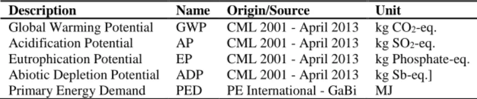
The method is based on a life cycle approach and on multiple criteria. This is however devoted to the proposal of an advanced modeling of the use phase. The end of life stage is also considered, and the manufacturing step is based on a simplifying assumption. The environmental impact indicators used in this article are described in Table 1:
Table 1. List of environmental impact indicators
Description Name Origin/Source Unit
Global Warming Potential Acidification Potential Eutrophication Potential Abiotic Depletion Potential Primary Energy Demand
GWP AP EP ADP PED CML 2001 - April 2013 CML 2001 - April 2013 CML 2001 - April 2013 CML 2001 - April 2013 PE International - GaBi kg CO2-eq. kg SO2-eq. kg Phosphate-eq. kg Sb-eq.] MJ
The method is designed based on a literature review of environmental assessments of batteries from which the influential parameters are deducted. From these data, a model is proposed and tested. This model is based on the process WtW. Environmental impacts from WtT and TtW of both fuel and electricity are related to the mass of the battery. Moreover, the ZEV mode ratio over the life cycle is based on an equation.
3 Modeling and solving with constraint satisfaction problems
In this section, CSP and classical CP algorithms used within Ibex C++ library (“IBEX library homepage,” 2014) are explained.
A CSP is formalized as follows (Rossi et al., 2006): this is a triple (𝑋, 𝐷, 𝐶) such that: - 𝑋 = {𝑥1, 𝑥2, … , 𝑥𝑛} is a finite set of variables of the problem;
- 𝐷 = {𝑑1, 𝑑2, … , 𝑑𝑛} is a finite set of domains of variation for variables in 𝑋 such that:
∀𝑖 ∈ {1, … , 𝑛}, 𝑥𝑖∈ 𝑑𝑖 (1)
- 𝐶 = {𝑐1, 𝑐2, … , 𝑐𝑝} is a finite set of p constraints of the problem. A constraint is defined
as any relation that restricts values of variables. It can be any type of mathematical relationships (equation, inequality, etc.) as well as explicit relations between variable values like tuples in a database.
5/21
Solving a CSP consists in instantiating each of the variable X while respecting the domains of variation D and satisfying the set of constraints C. A solution x to a given CSP can be defined as:
𝑥 ∈ 𝐷 | ∀𝑖 ∈ {1, … , 𝑝} 𝑐𝑖(𝑥) is satisfied (2)
In this study, numerical CSPs are considered, i.e. CSPs dealing with continuous variables which domains are intervals of real numbers. Ibex solver aims at solving numerical CSPs to compute reliable solutions, approximated using boxes (Cartesian products of intervals) that satisfy all the constraints. This library is based on interval arithmetic and programming by contractors (Chabert and Jaulin, 2009). A contractor is a solving operator that reduces the size of an input box by removing inconsistent values regarding a given constraint while ensuring that no valid solutions are lost (Benhamou et al., 1999). They are generally used in a generic algorithm called Branch-and-Prune to compute the whole set of solutions (Van Hentenryck et al., 1997). At each iteration, a box to be processed is chosen. Contractors are applied to prune this box. If the expected precision is not attained and the box is not empty, the box is split and resulting boxes are put in the list of boxes to process. Otherwise and if not empty, the box corresponds to a solution. The algorithm terminates when no more boxes to process remains.
With the intuitive syntax Minibex (“The Minibex Language — IBEX 2.2.0 documentation,” 2014) that is integrated in Ibex, modeling of the problem is greatly simplified. Indeed, solving algorithms are separated from modeling. Ibex then forms a “black box” which will not be detailed more in deep. Regarding modeling, a CSP is declared as an input text file for Ibex. First, the list of the variables with their domains of variation is defined, e.g. GWP indicator is defined over R+: GWP in [0,∞].
Then constraints can be defined as classical algebraic equations or inequations. Ibex offers two types of resolution: a global solver (ibexSolver) and a global optimizer (ibexOptimizer). The global solver computes, the whole set of solutions, whereas the global optimizer computes the best solution minimizing a mathematical expression (e.g. a variable which value is computed by the system of equation). In this case, a generic Branch-and-Bound algorithm is used instead of the Branch-and-Prune. The major difference is that some boxes to be processed are eliminated when a solution is found and proved to be better than those boxes regarding the minimizing objective. For this study, it will minimize the GWP environmental indicator, but any other environmental indicator in the model can be used instead.
4 Methodology for EcoBatt tool
In this chapter, EcoBatt tool is presented. EcoBatt is a software developed in C++ that aims to: - simulate use scenarios of PHEV or BEV;
- calculate the environmental profile of those scenarios; - find the optimized scenario.
EcoBatt combines life cycle assessment (LCA) and CSP modeling and solving. The combination of both methodologies still found little studies in the literature. Most of the time, CSP is used on a discrete mode by using parameter databases. For designing an eco-compatible hybrid passenger ferry, Tchertchian et al. (2016) define one table for each ferry’s subsystem
6/21
they want to optimize. Each table contains different pre-defined configurations of the system. CSP is used to find the optimized configuration of the ferry among all the possible sub-systems configurations. Here, EcoBatt uses a continuous model where all the decision variables are defined by an interval domain.
The environmental evaluations of traction batteries in the literature make simplifying assumptions for the use phase. Zackrisson et al. (2010) define one electric consumption and does not evaluate the influence of the ZEV mode share in the total journey. Indeed, simulating different scenarios with conventional LCA software may be long; this may involve changes in the LCA model. Here, the focus is made on the use phase. The goal is to provide the opportunity to simulate different usage scenarios without changing the model.
4.1 Global overview of EcoBatt
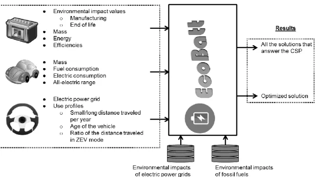
EcoBatt aims to create battery usage scenario and to calculate the associated environmental impacts. For a life cycle perspective, EcoBatt must take into account LCA results of the other life cycle steps. But as EcoBatt do not include LCA databases, the environmental impacts of the other life cycle steps must be calculated by the appropriate LCA software (Figure 1). Only fuel and power grid environmental impacts are required in EcoBatt.
Figure 1. Schematic overview of EcoBatt inputs
By limiting the boundaries of the study to the battery system, one can count two main sources of environmental impacts during the use phase: energy use to transport the battery in the PHEV or BEV, and potential acts of service on battery such as the replacement of a module or of the entire battery. Therefore, six kinds of parameters have been chosen to simulate the use phase:
- The utilization rate of thermal energy and electric power on distance lifecycle: it aims to calculate the share of the path traveled in ZEV mode;
7/21
- The fuel quantity to transport the battery in the vehicle: it aims to calculate the environmental impacts to produce fossil fuels (Diesel or gasoline) for PHEV;
- The carbon dioxide and pollutant emissions from fuel combustion: it aims to calculate the environmental impacts from fossil fuel combustion for PHEV;
- The electric energy to transport the battery in the vehicle: it aims to calculate the environmental impacts to produce electricity for driving PHEV or BEV;
- The environmental impacts from battery manufacturing and end-of-life: although EcoBatt is focused on the use phase, adopting a life cycle point of view is better; - The lifetime of the battery: linked to the environmental impacts from battery
manufacturing and end-of-life, it aims to simulate the replacement of a module or the entire battery. Please note that in the case study, the battery is considered to fulfill the vehicle life time.
To accommodate the use of fossil and/or electric energy, some studies include the vehicle in the boundaries of the studied system and consider the total consumption of the vehicle (Notter et al., 2010). Others limit the system to the battery (thus excluding the vehicle) and assess the impact of the mass of the battery using a simulation software (Matheys et al., 2009). Others use a reduction value of energy consumption to the battery (Zackrisson et al., 2016). As part of this study, assignment to the battery fuel consumption of the vehicle and electricity, as well as carbon dioxide emissions and pollutants, is performed using coefficients which will be described in this section.
4.2 Utilization rate of thermal energy and electric power on distance lifecycle: the Utility Factor
Contrary to BEV that drives its entire life with electricity, a PHEV uses both fossil fuels and electricity. It is therefore necessary to know the distribution of the use of each of these two energies on the full life cycle distance. Bradley and Quinn (2010) have analyzed the J2841 standards issued by the Society of Automotive Engineers (SAE) (Society of Automotive Engineers, 2010) that defines a method of calculating the Utility Factor (UF) as the ratio of the distance traveled in ZEV mode on the total distance of a daily commute. This ratio is a function of the all-electric range (AER) of the PHEV and involves a sextuplet of parameters {𝐶𝑖}1≤𝑖≤6
(see equation (3)). Bradley and Quinn define nineteen sextuplets, each connected to a particular use of the vehicle characteristics studied (age of vehicle, distance traveled per year, etc.). Thus, knowing the AER of the vehicle (here in kilometers), one can determine the part of the journey performed in ZEV mode on the lifecycle.
𝑈𝐹(𝐴𝐸𝑅) = 1 − 𝑒𝑥𝑝 (− ∑ 𝐶𝑖. (𝐴𝐸𝑅 (1,609344.400)⁄ )𝑖 6
𝑖=1
) (3)
With 𝐴𝐸𝑅 All-electric range [km]
{𝐶𝑖} Sextuplet of parameters [-]
4.3 Fuel mass to transport the battery
In this study, about 30% of the fuel consumption of a vehicle is considered to be due to its mass (Zackrisson et al., 2010). For the fossil fuel, the Fuel Reduction Value (FRV) defined by Koffler
8/21
and Rohde-Brandenburger (2010) is used and is equal to 0.12 or 0.15 L / (100 km.100 kg) respectively for Diesel or gasoline.
In the case where the total fuel consumption of the vehicle is unknown, the factor FRV is used as defined by Koffler and Rohde-Brandenburger (2010). The weight of fuel consumed for the transport of the battery is expressed by equation (4). Note that if the application is a BEV, the Utility Factor is set at UF = 1.
𝑀𝑓𝑢𝑒𝑙,𝑏𝑎𝑡𝑡=
𝐹𝑅𝑉
10000. 𝑀𝑏𝑎𝑡𝑡. 𝜌𝑓𝑢𝑒𝑙. 𝐷. (1 − 𝑈𝐹) (4) With 𝐹𝑅𝑉 Fuel Reduction Value = 0.12 Diesel; 0.15 Gasoline [L/(100 kg * 100 km)]
𝑀𝑏𝑎𝑡𝑡 Battery mass [kg]
𝜌𝑓𝑢𝑒𝑙 Fuel density = 0.84 Diesel; 0.74 Gasoline [kg/L]
𝐷 Life cycle distance [km]
𝑈𝐹 Utility Factor [%]
𝑀𝑓𝑢𝑒𝑙,𝑏𝑎𝑡𝑡 Fuel mass for transporting the battery [kg]
In the case where the total fuel consumption of the vehicle 𝐶𝑓𝑢𝑒𝑙,𝑉 [L / 100 km] is known, a
portion of 𝐶𝑓𝑢𝑒𝑙,𝑉 is believed to be due to the vehicle mass 𝑀𝑉 [kg]. To assign to the battery the fuel that effectively allows the transport of it, an allocation of fuel consumption is done with the coefficient 𝛼𝑓𝑢𝑒𝑙; like Zackrisson et al. (2010) it is estimated to be approximately 𝛼𝑓𝑢𝑒𝑙 = 30%. The mass of fuel consumed for the transport of the battery is expressed by the equation (5). 𝑀𝑓𝑢𝑒𝑙,𝑏𝑎𝑡𝑡= 𝛼𝑓𝑢𝑒𝑙. 𝑀𝑏𝑎𝑡𝑡 𝑀𝑉 . 𝐶𝑓𝑢𝑒𝑙,𝑉 100 . 𝜌𝑓𝑢𝑒𝑙. 𝐷. (1 − 𝑈𝐹) (5)
With 𝛼𝑓𝑢𝑒𝑙 Mass allocation coefficient of fuel consumption = 30 [%]
𝑀𝑏𝑎𝑡𝑡 Battery mass [kg]
𝑀𝑉 Vehicle mass [kg]
𝐶𝑓𝑢𝑒𝑙,𝑉 Fuel consumption of vehicle V [L / 100 km]
𝜌𝑓𝑢𝑒𝑙 Fuel density = 0.84 Diesel; 0.74 Gasoline [kg/L]
𝐷 Life cycle distance [km]
𝑈𝐹 Utility Factor [%]
𝑀𝑓𝑢𝑒𝑙,𝑏𝑎𝑡𝑡 Fuel mass for transporting the battery [kg]
The fuel mass calculated is then connected to the environmental impacts of the fuel manufacturing phase, that is to say, step WtT. In the next paragraph, it is to explain how the next stage, that of TtW, is taken into account for fossil fuels.
Note here that the vehicle mass 𝑀𝑉 is equal to the sum of the mass of the battery 𝑀𝑏𝑎𝑡𝑡 and the mass of the “base” 𝑀𝑏𝑎𝑠𝑒. This “base” vehicle corresponds to the vehicle not equipped with the traction battery.
4.4 CO2 and pollutant emissions from fuel combustion
The combustion of fuel in internal combustion engines (ICE) is a source of CO2 and pollutants
emissions. The emissions of CO2 can easily be connected to the mass of the battery since it is
proportionally related to the fuel consumption. However, it is very difficult to establish a link between fuel consumption and vehicle emissions of pollutants; these depend on the fuel used and the vehicle's emission control system that is dimensioned to meet European regulations.
9/21
Thus, the amount of CO2 emitted through combustion and related to the battery is calculated
(see equation (6)) by multiplying the fuel mass consumed in the life cycle and related to the battery (from equation (5)) with the CO2 emission factor 𝜏𝐶𝑂2 [kg CO2 / kg fuel]. The values of
this factor for gasoline and Diesel are respectively 3.17 and 3.16 kg CO2 / kg fuel (Joint
Research Centre et al., 2013).
𝑀𝐶𝑂2,𝑏𝑎𝑡𝑡= 𝜏𝐶𝑂2. 𝑀𝑓𝑢𝑒𝑙,𝑏𝑎𝑡𝑡 (6) With 𝜏𝐶𝑂2 CO2 emission factor = 3.16 Diesel; 3.17 Gasoline [kg CO2 / kg fuel]
𝑀𝑓𝑢𝑒𝑙,𝑏𝑎𝑡𝑡 Fuel mass for transporting the battery [kg] 𝑀𝐶𝑂2,𝑏𝑎𝑡𝑡 Amount of CO2 emitted through combustion [kg]
Pollutants included in this study are carbon monoxide (CO), nitrogen oxides (NOx) and hydrocarbons (HC). It is assumed that the amount of emitted pollutants is calculated from regulatory thresholds of emissions over the life cycle, based on the weight of the battery by an equation analogous to that of the fuel mass of the equation (5). It is a hypothesis that is objectively false because, firstly, the emissions of pollutants measured on homologated cycle are below regulatory thresholds, and secondly, there is no scientific study linking these emissions and the mass of the vehicle. However, it is less wrong to regard this false assumption than to consider no pollutant emission linked to transport the battery with thermal energy. Here, the pollutant emission coefficients are supposed to be equal to the thresholds of the Euro VI standard. This assumption is formalized with equation (7):
( 𝑀𝐶𝑂,𝑏𝑎𝑡𝑡 𝑀𝑁𝑂𝑥,𝑏𝑎𝑡𝑡 𝑀𝐻𝐶,𝑏𝑎𝑡𝑡 ) = 𝛼𝑓𝑢𝑒𝑙. 𝑀𝑏𝑎𝑡𝑡 𝑀𝑉 . ( 𝑒𝐶𝑂 𝑒𝑁𝑂𝑥 𝑒𝐻𝐶 ) . 𝐷. (1 − 𝑈𝐹) (7)
With 𝑀𝑋,𝑏𝑎𝑡𝑡 Mass of the pollutant 𝑋 related to the battery [kg] 𝑒𝑋 Emission of pollutant 𝑋 : ( 𝑒𝐶𝑂;𝐷𝑖𝑒𝑠𝑒𝑙/𝐺𝑎𝑠𝑜𝑙𝑖𝑛𝑒 𝑒𝑁𝑂𝑥;𝐷𝑖𝑒𝑠𝑒𝑙/𝐺𝑎𝑠𝑜𝑙𝑖𝑛𝑒 𝑒𝐻𝐶;𝐷𝑖𝑒𝑠𝑒𝑙/𝐺𝑎𝑠𝑜𝑙𝑖𝑛𝑒 ) = ( 500 / 1000 80 / 60 90 / 100 ) . 10 −6 [kg / km]
𝛼𝑓𝑢𝑒𝑙 Mass allocation coefficient of fuel consumption = 30 [%]
𝑀𝑏𝑎𝑡𝑡 Battery mass [kg]
𝑀𝑉 Vehicle mass [kg]
𝐷 Life cycle distance [km]
𝑈𝐹 Utility Factor [%]
4.5 Electric energy
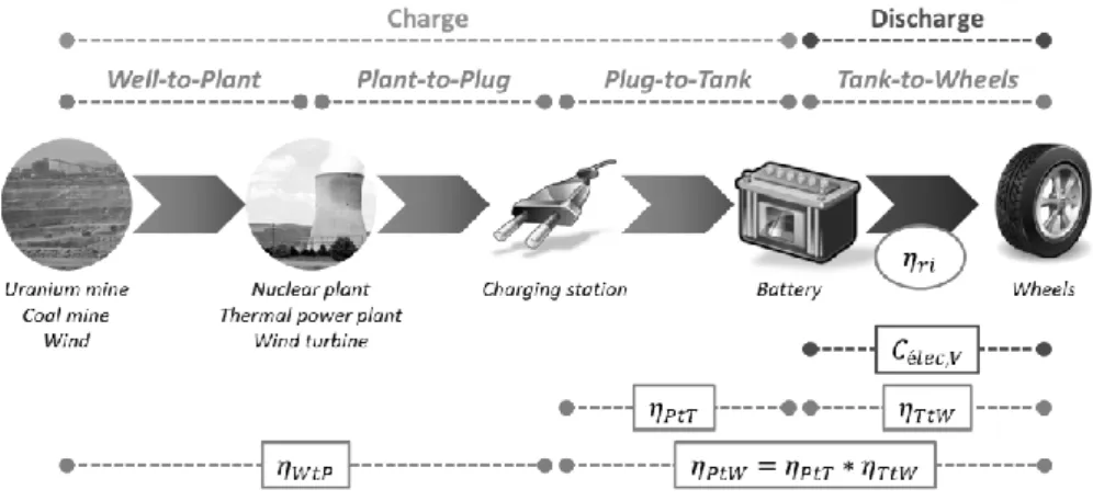
As described above, fossil fuel use imposes a decomposition of environmental impacts on two phases: the WtT and the TtW. Such decomposition can be resumed for electricity: the first step is the battery charge; the second is the battery discharge (see Figure 2). The transmission of it to the vehicle’s wheels must be taken into account in the WtW. These two functional states of the battery are represented by the Plug-to-Wheels (PtW) process. PtW energy efficiency 𝜂𝑃𝑡𝑊 [%] is due to the charging efficiency 𝜂𝑃𝑡𝑇 [%] and to the conversion of electric energy to
mechanical energy and its transmission to the wheels 𝜂𝑇𝑡𝑊 [%]. Internal losses and the
additional load due to battery conditioning are included in the internal efficiency of the battery 𝜂𝑟𝑖 [%].
10/21
Furthermore, energy efficiency Well-to-Plug (WtP) 𝜂𝑊𝑡𝑃 [%] from different ways of producing
electricity, including losses due to transmission and distribution to the end consumer, is directly addressed via databases used from the GaBi ts life cycle analysis software (“Life Cycle Assessment LCA Software: GaBi Software,” 2017).
Figure 2. Electricity Well-to-Wheels cycle.
All-electric range (AER) of the vehicle corresponds to a complete discharge of the battery, without any strategy for energy optimization is assigned. The amount of electrical energy to carry the battery depends on the AER which is also the input data for the calculation of the UF. It is through this variable that the knowledge or not of the total electricity consumption of the vehicle is taken into account. If it is unknown, then the AER is formulated by equation (8).
𝐴𝐸𝑅 = 𝐸𝑢
𝑀𝑉. 𝐾𝑒𝑙𝑒𝑐
(8)
With 𝐸𝑢 Battery useful energy [kW.h]
𝑀𝑉 Vehicle mass [kg]
𝐾𝑒𝑙𝑒𝑐 Electricity mass consumption of the vehicle = 120 [kW.h / (km *kg)]
Conversely, if the total electricity consumption of the vehicle 𝐶𝑒𝑙𝑒𝑐,𝑉 is known, then the AER is obtained with the equation (9).
𝐴𝐸𝑅 = 𝐸𝑢
𝐶𝑒𝑙𝑒𝑐,𝑉 (9)
With 𝐸𝑢 Battery useful energy [kW.h]
𝐶𝑒𝑙𝑒𝑐,𝑉 Electricity consumption of the vehicle [kW.h / km]
𝐴𝐸𝑅 All-electric range [km]
In this study, about 30% of the electricity consumption of a vehicle is considered to be due to its mass (Zackrisson et al., 2016, 2010). The mass consumption of electricity is close to 100-130 W.h/(km.t) (Menga and Ceraolo, 2008). By default, an electricity mass consumption 𝐾𝑒𝑙𝑒𝑐 = 120 W.h/(km.t) (equation (8)) is retained. The equation by setting the amount of electrical energy to transport the battery is expressed by equation (10). It shows, within brackets, the amount of energy relative to the mass of the battery that is necessary to draw on the power grid to carry the battery, and the amount of energy lost on the life cycle rolling because of internal losses and conditioning.
𝐸𝑒𝑙𝑒𝑐,𝑏𝑎𝑡𝑡= 𝐸𝑢 𝐴𝐸𝑅. [ 𝛼𝑒𝑙𝑒𝑐. 𝑀𝑏𝑎𝑡𝑡 𝜂𝑃𝑡𝑇. 𝑀𝑉 + (1 − 𝜂𝑟𝑖)] . 𝐷. 𝑈𝐹 (10)
11/21
With 𝐸𝑢 Useful energy [kW.h]
𝐴𝐸𝑅 All-electric range [km]
𝛼𝑒𝑙𝑒𝑐 Mass allocation coefficient of the vehicle electricity consumption = 30 [%]
𝑀𝑉 Vehicle mass [kg] 𝑀𝑏𝑎𝑡𝑡 Battery mass [kg] 𝜂𝑟𝑖 Internal efficiency [kW.h] 𝜂𝑃𝑡𝑇 Plug-to-Tank efficiency [kW.h] 𝐷 Lifecycle distance [km] 𝑈𝐹 Utility Factor [%]
𝐸𝑒𝑙𝑒𝑐,𝑏𝑎𝑡𝑡 Total amount of electricity [kg]
4.6 Manufacturing and end-of-life steps
A simple model of manufacturing and end-of-life steps will be used. It combines both mass and useful energy of the battery. The energy of a battery is calculated by the multiplication of the number of cells with their capacity and their voltage. So, increasing the number of cells is a way to increase the energy of the battery. By increasing the number of cells, the mass of the modules is proportionally increased. Therefore, the useful energy of the battery is proportionally linked to the battery mass. The proportionality coefficient is assumed to be different from a battery technology to another. Thus, while mass and useful energy of an initial battery are supposed to be known, it is possible to vary the mass of the battery and calculate the useful energy of the resized battery.
𝐸𝑢∗=
𝐸𝑢
𝑀𝑏𝑎𝑡𝑡𝑀𝑏𝑎𝑡𝑡
∗ (11)
With 𝐸𝑢 Useful energy of the initial battery [kW.h]
𝑀𝑏𝑎𝑡𝑡 Mass of the initial battery [kg] 𝐸𝑢∗ Useful energy of the resized battery [kW.h] 𝑀𝑏𝑎𝑡𝑡∗ Mass of the resized battery [kg]
In addition, a proportional relationship between the mass of the battery and the environmental impacts associated with its manufacture and its end-of-life is considered.
4.7 Using EcoBatt tool
EcoBatt has been developed in C++ with the software Qt Creator 2.0.1 (based on Qt 4.7.0). An interface helps the user to describe the batteries to be compared, the vehicle, and the usage scenarios. The user then launches the calculation. For each run, the following steps are followed:
Step 1: compilation of a text file (see Annex I) that describes the problem containing: o The constants
o The variables with their variation domain; o The constraints
Step 2: call of the text file in the ibexSolver or ibexOptimizer function; Step 3: resolution of the problem with Ibex;
Step 4: generation of results:
12/21
o If ibexOptimizer is used, the optimized solution is generated directly in the EcoBatt’s interface.
5 Li-ion battery case study
5.1 Context and initial data
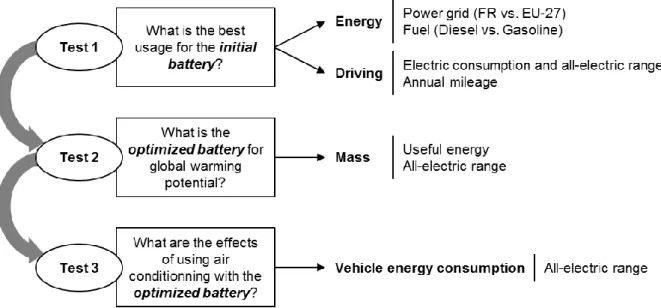
Here is proposed to check the model validity looking at the global behavior and sensitivity. So, the method is applied to a Li-ion battery for a PHEV application (see Figure 3). Firstly, the effect of power grid, fuels, all-electric range, and ZEV mode ratio, on GWP are tested with the global solver. Secondly, an optimum mass of the battery is sought; the goal is to test the global optimizer by looking for a new sizing of the battery that is more environmental friendly. Lastly, a sensitivity analysis is performed on the use of air conditioning on the battery that has been optimized in the previous step; the goal is to test the global solver by sensitivity of the model to the electric consumption of the PHEV.
Figure 3. Schematic description of the experimentation with test goals and observed phenomena Let be a Li-ion battery (LiMnO2) whose characteristics are:
Mbatt = 200 kg
Etot = 16.3 kW.h
Eu = 14.5 kW.h
ηPtT = 90%
ηri = 90%
Let be a PHEV with the battery above. PHEV technical and usage characteristics are the following:
MV = 1600 kg
AER = 75.5 km (Kélec = 120 W.h/(km.t))
13/21
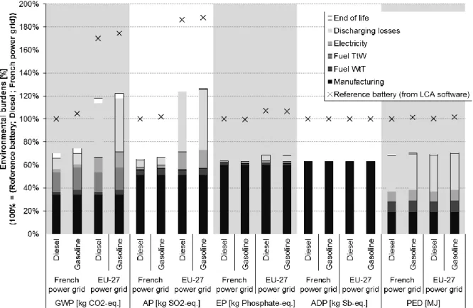
The manufacturing data have been calculated by a Life Cycle Assessment (LCA) software. The environmental profile is shown on the Figure 4. This histogram and all the graphics of this study have adopted the reference to be 100% for the life cycle impact of the Diesel PHEV battery on French electricity mix.
Figure 4. Environmental profile of the input Li-ion battery for a PHEV obtained from a LCA software. 100% reference is considered to be the life cycle impacts of Diesel PHEV on French power grid.
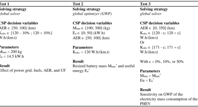
The experiment is performed on two electric mixes (France and EU-27) with two fossil fuels (Diesel and gasoline). Four combinations {electricity mix; fuel} are possible. Three tests are presented in the section (see Figure 3 and Table 2).
The first test aims at validating the model regarding the impact of the power grid, fuels, all-electric range (AER) and battery usage ratio (UF) on the GWP. As EU-27 and French power grids are different in carbon intensity, a clear distinction between them is expected. It is also expected that the more the battery is used, the more GWP should decrease since PHEV technology aims to decrease fuel consumption.
The second test consists in seeking a battery mass that minimizes the global warming potential on the manufacturing and use steps. As shown in equation (11), the useful energy is linked by a linear function to the mass of the battery; moreover, as shown in equations (8) or (9), the all-electric range is also linked to the useful energy by a linear function. So, by optimizing the battery mass, both the manufacturing and the use steps are expected to be optimized.
The third one consists in a sensitivity analysis on the electricity mass consumption of the vehicle (Kelec) and the effect of using air conditioning on GWP. Air conditioning should increase the
14/21 Table 2. Variable description of the three tests
Test 1 Test 2 Test 3
Solving strategy global solver CSP decision variables AER [50; 100] (km) Kelec [120 – 10% ; 120 + 10%] W.h/(km.t) Parameters Mbatt = 200 kg Eu = 14.5 kW.h Result
Effect of power grid, fuels, AER, and UF
Solving strategy global optimizer (GWP) CSP decision variables Mbatt [100; 300] (kg) Eu [0; 50] (kW.h) AER [50; 100] (km) Parameters Kelec = 120 W.h/(km.t) Result
Resized battery mass Mbatt* and useful
energy Eu* Solving strategy global solver CSP decision variables AER [0; 350] (km) Kelec [120 - ; 120 + ] W.h/(km.t) Or Kelec [171 - ; 171 + ] W.h/(km.t) With = 0%, 10%, or 50% Parameters Mbatt = Mbatt* Eu = Eu* Result Sensitivity on GWP of the electricity mass consumption of the PHEV
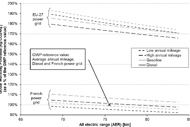
5.2 Effects of power grid, fuels, all-electric range, and utility factor on global warming potential
For the first test, the global solver has been used in order to have the evolution of the environmental indicator GWP as a function of AER for the four combinations {power grid; fuel} and for two sextuplets of parameters {𝐶𝑖}1≤𝑖≤6 for the calculation of UF (low and high
annual mileages, see Bradley and Quinn (2010)). UF is calculated with equation (3). AER and Kelec are the only decision variables of the CSP model. Both variables are constrained by
equation (8). The electric consumption of the vehicle is calculated by equation (9). Battery fuel and electricity consumptions are respectively calculated by equations (4) and (10). CO2 and
pollutant emissions are respectively calculated by equations (6) and (7). The results are shown on the Figure 5.
As expected, the curves of EU-27 and French power grids are clearly separated because the difference between both power grids is significant.
GWP is decreasing while the AER is increasing whatever the combination and the UF calculation mode, so the more the electric consumption is optimized, the more the GWP is decreased.
For French power grid, high annual mileage generates more impacts than low annual mileage, and it is the contrary for EU-27 power grid. Low annual mileage corresponds to high UF. So, as Figure 5 shows, the GWP is lower when ZEV mode is more used than the internal combustion engine on the French power grid, and the contrary on the EU-27 power grid. So, the less the ZEV mode is used on a high carbon intensity power grid, the less the GWP. Concerning the fuels, using Diesel has a lower effect on GWP than using gasoline. Nevertheless, for each power grid, the zones defined by the fuels and the annual mileages are partially overlapping. Therefore, the difference of fuels is not very significant on the GWP.
15/21
AER is varying between 68 and 84 km while its initial domain of variation was defined between 50 and 100 km. So, the interval of solutions of AER has been reduced and adapted to the domain of variation of Kelec. It is an expected result because of equation (8) that links AER to Kelec.
Figure 5. Evolution of the global warming potential as a function of the all-electric range, for EU-27 and French electricity mixes, gasoline and Diesel fossil fuels, and low and high annual mileages. 100% reference is considered to be the life cycle
GWP value of the input battery with French power grid and Diesel.
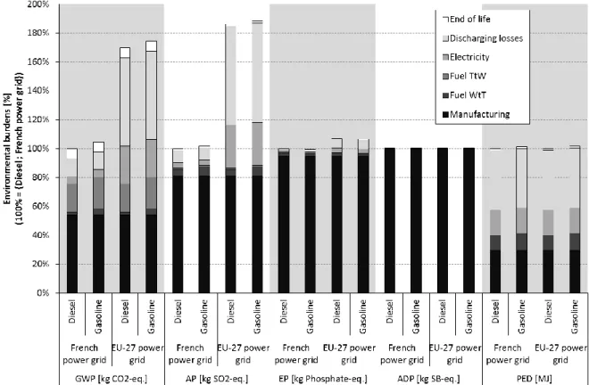
5.3 Optimization of the battery mass and the useful energy
For the second test, the global optimizer has been used in order to seek the optimum mass of the battery for minimizing the GWP. The link between mass and useful energy is calculated by the equation (11). The all-electric range is calculated with equation (8). So, as the battery mass is a decision variable, the battery energy and the all-electric range are also decision variables. The sextuplet of parameters to calculate UF is the average passenger car (see Bradley and Quinn (2010)). The results for all the environmental indicators considered in this paper are shown on the Figure 6.
While the optimization strategy is to minimize GWP, all the environmental indicators have been reduced. The optimum mass of the battery is 130 kg while AER value is 50 km whatever the combination {electricity mix; fuel}. However, as shown in Test 1, the AER should be high for decreasing GWP. Therefore, the mass of the battery is a decision variable that influences more this criterion than the AER.
16/21
Figure 6. Environmental profile of the resized Li-ion battery. 100% reference is considered to be the life cycle impacts of the input battery with French power grid and Diesel.
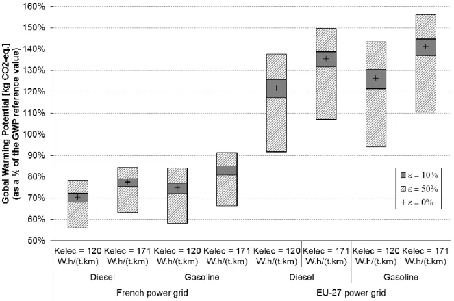
5.4 Sensitivity study of the electricity mass consumption of the PHEV
For the third test, the global solver has been used in order to make a sensibility analysis on the electricity mass consumption of the vehicle (Kelec). This sensivity analysis can also be viewed
as the way to take into account uncertainties about some average or statistical data used in the model. Two values have been used: the initial 120 W.h/(km.t) and 171 W.h/(km.t). The second value corresponds to the use of air conditioning that may decrease the AER by 30%. The sextuplet of parameters to calculate UF is the average passenger car. As a decision variable, the domain of variation of Kelec has to be defined: Kelec [120 – ; 120 + ] and Kelec,air conditioning
[171 – ; 171 + ] with = 0%, 10%, and 50%. AER and Kelec are constrained by equation (8).
The results are shown in the Figure 7.
There is again a clear separation between the results on French and EU-27 power grids. The use of air conditioning increases significantly the GWP of 10% when used on EU-27 power grid. Another observation concerns the GWP interval of solutions with = 50%. It is decentered downwards. This shift is explained by the exponential nature of the function which connects the UF to the AER. Indeed, while Kelec decreases, AER increases, and conversely. Moreover,
while AER increases, UF increases relatively to the exponential nature of the function that links both variables (see equation (3)), and conversely. One can interpret this observation as follows: the GWP faster decreases by the decline of the PHEV electricity consumption than it increases by the rise of PHEV electricity consumption.
17/21
Figure 7. Sensitivity results of the GWP of the electricity mass consumption of the vehicle with and without air conditioning. For each value, three domain of variation are used. 100% reference is considered to be the life cycle GWP value of the input
battery with French power grid and Diesel.
6 Conclusion
In this article, a novel approach for environmental assessment of the use phase of a product has been presented. It is based on Constraint Programming and CSP modeling. A decision support tool (EcoBatt) was developed to help car maker in the choice or sizing of a hybrid or all-electric technology. This tool is applied on a Li-on battery with realistic use profiles in the automotive industry. CSP allows making different simulations with the same model; in the case study, tests 1 to 3 have been made with the same CSP model. The power grid used to recharge makes the biggest difference of the GWP for the same battery. Optimizing the GWP makes decrease all the other environmental impacts. Lastly, the GWP faster decreases by the decline of the PHEV electricity consumption than it increases by the rise of PHEV electricity consumption.
The model used in this work is complete enough to express advanced usage scenarios as currently used in the automotive industry. The solving technology allows to easily compute optimized solutions in a design phase. The multiple environmental indicators can be used in further investigations to define the best solution with multiple criteria decision methods like AHP (Analytic Hierarchy Process).
The power grid, the share of the path traveled in ZEV mode, the mass of the battery, and the electric mass consumption of the vehicle, are highly sensitive data. Future works may be investigated to improve the model and to reduce this effect and/or to integrate the robustness of solutions in the solving process.
18/21
There are three main limitations to the method. First, the electric consumption of the vehicle is supposed to be calculated theoretically on a full battery discharge. So, no strategy for energy optimization is assigned. This is a bias that may have effect on other parameters like the all-electric range and consequently on the share of the path traveled in ZEV mode. Strategies for energy consumption may be implemented in the model by using other parameters like the state of charge (SOC) of the battery.
Second, simplifying assumptions are used for the battery manufacturing and end-of-life phases. A more detailed modeling could be obtained by connecting the physical and chemical equations to the performance and environmental impacts. For manufacturing, these data are nevertheless controlled by the battery supplier of the car maker and are hard to get. For the end-of-life, there are few PHEV or BEV that currently reach the end of their lifes. In this research, data come from a battery recycling process prototype from a recycler, so the model will be improved when the process will be industrialized.
Third, there is the lack of an aging model for batteries. Of course, the charge/discharge energy efficiency decreases as the age of battery cells increase. This problematic phenomenon is generally taken into account during the design. This is a parameter of the model that is easy to manipulate. A scenario for modeling an old battery can be made where the efficiency is decreased and the other parameters are constant. A constant interval to represent this uncertainty about the efficiency value can be used but the propagation of uncertainties in the model to avoid too imprecise computed solutions should be more investigated.
Other battery technologies can be evaluated through EcoBatt, provided that the characteristics of the batteries are easily accessible to car manufacturers. For example, Lithium iron phosphate (LFP) batteries may be evaluated provided that the energy overconsumption for running the battery is considered in the internal efficiency parameter. Moreover, extended to entire vehicle system, this method is promising to compare alternative solutions for vehicle subsystems. Obviously models must be defined for them, but the whole method and the solving steps are generic enough. Ultimately the optimum configuration from an environmental point of view of the vehicle could be determined upstream of the design whereas currently environmental assessments with LCA tools are used afterwards.
Acknowledgements
This research was supported by the French environment agency (Ademe) and the EcoSD Network.
7 References
Benhamou, F., Goualard, F., Granvilliers, L., Puget, J.-F., 1999. Revising Hull and Box Consistency, in: Proceedings of the 1999 International Conference on Logic Programming. Massachusetts Institute of Technology, Cambridge, MA, USA, pp. 230– 244.
Bradley, T.H., Quinn, C.W., 2010. Analysis of plug-in hybrid electric vehicle utility factors. Journal of Power Sources 195, 5399–5408. doi:10.1016/j.jpowsour.2010.02.082
19/21
Chabert, G., Jaulin, L., 2009. Contractor programming. Artificial Intelligence 173, 1079–1100. doi:10.1016/j.artint.2009.03.002
Chenouard, R., Granvilliers, L., Sebastian, P., 2009. Search heuristics for constraint-aided embodiment design. AI EDAM 23, 175–195. doi:10.1017/S0890060409000055 Dunn, J.B., Gaines, L., Sullivan, J., Wang, M.Q., 2012. Impact of Recycling on Cradle-to-Gate
Energy Consumption and Greenhouse Gas Emissions of Automotive Lithium-Ion Batteries. Environ. Sci. Technol. 46, 12704–12710. doi:10.1021/es302420z
European Parliament Council, 2009. Regulation No 443/2009 of the European Parliament and of the Council of 23 April 2009 setting emission performance standards for new passenger cars as part of the Community’s integrated approach to reduce CO 2 emissions from light-duty vehicles.
Faria, R., Marques, P., Moura, P., Freire, F., Delgado, J., de Almeida, A.T., 2013. Impact of the electricity mix and use profile in the life-cycle assessment of electric vehicles. Renewable and Sustainable Energy Reviews 24, 271–287. doi:10.1016/j.rser.2013.03.063
Girardi, P., Gargiulo, A., Brambilla, P.C., 2015. A comparative LCA of an electric vehicle and an internal combustion engine vehicle using the appropriate power mix: the Italian case study. The International Journal of Life Cycle Assessment. doi:10.1007/s11367-015-0903-x
IBEX library homepage, 2014. www.ibex-lib.org/ (accessed 4.3.17).
Joint Research Centre, Eucar, Concawe, 2013. Well-to-Wheels analysis of future automotive fuels and powertrains in the European context, Tank-to-wheels (TTW) report, version 4 (Technical Report No. EUR 26028 EN). Publications Office of the European Union, Luxembourg, Luxembourg.
Koffler, C., Rohde-Brandenburger, K., 2010. On the calculation of fuel savings through lightweight design in automotive life cycle assessments. Int J Life Cycle Assess 15, 128–135. doi:10.1007/s11367-009-0127-z
Larroude, V., Yvars, P.-A., Millet, D., 2011. Global optimization of environmental impact by a constraint satisfaction approach – application to ship-ecodesign, in: Proceedings of the 18th International Conference on Engineering Design (ICED 11), Impacting Society through Engineering Design, Design for X, Design to X. The Design Society, pp. 46– 59.
Lee, J.T., Kwon, S., Lim, Y., Chon, M.S., Kim, D., 2013. Effect of Air-Conditioning on Driving Range of Electric Vehicle for Various Driving Modes (SAE Technical Paper No. 2013-01-0040). SAE Technical Paper, Warrendale, USA.
Life Cycle Assessment LCA Software: GaBi Software, 2017. www.gabi-software.com/international/index/ (accessed 4.3.17).
Matheys, J., Timmermans, J.-M., Van Mierlo, J., Meyer, S., Peter Van den Bossche, 2009. Comparison of the environmental impact of five electric vehicle battery technologies using LCA. International Journal of Sustainable Manufacturing 1, 318–329. doi:10.1504/IJSM.2009.023977
Menga, P., Ceraolo, M., 2008. An evaluation of global environmental and energy value of vehicle technologies. Presented at the 3rd European Ele-Drive Transportation Conference, Geneva, Switzerland.
20/21
Meyer, Y., Yvars, P.-A., 2012. Optimization of a passive structure for active vibration isolation: an interval-computation- and constraint-propagation-based approach. Engineering Optimization 44, 1463–1489. doi:10.1080/0305215X.2011.652102
Nordelöf, A., Messagie, M., Tillman, A.-M., Söderman, M.L., Mierlo, J.V., 2014. Environmental impacts of hybrid, plug-in hybrid, and battery electric vehicles—what can we learn from life cycle assessment? Int J Life Cycle Assess 19, 1866–1890. doi:10.1007/s11367-014-0788-0
Notter, D.A., Gauch, M., Widmer, R., Wäger, P., Stamp, A., Zah, R., Althaus, H.-J., 2010. Contribution of Li-Ion Batteries to the Environmental Impact of Electric Vehicles. Environ. Sci. Technol. 44, 6550–6556. doi:10.1021/es903729a
Rossi, F., Beek, P. van, Walsh, T., 2006. Handbook of Constraint Programming, First. ed. Elsevier, New York, USA.
Society of Automotive Engineers, 2010. Utility Factor Definitions for Plug-In Hybrid Electric Vehicles Using 2001 U.S. DOT National Household Travel Survey Data (No. J2841). Hybrid - Ev Committee.
Tagliaferri, C., Evangelisti, S., Acconcia, F., Domenech, T., Ekins, P., Barletta, D., Lettieri, P., 2016. Life cycle assessment of future electric and hybrid vehicles: A cradle-to-grave systems engineering approach. Chemical Engineering Research and Design 112, 298– 309. doi:10.1016/j.cherd.2016.07.003
Tchertchian, N., Millet, D., Yvars, P.A., 2016. The influence of the level of definition of functional specifications on the environmental performances of a complex system. EcoCSP approach. International Journal of Sustainable Engineering 9, 277–290. doi:10.1080/19397038.2015.1085110
Tchertchian, N., Yvars, P.-A., Millet, D., 2013. Benefits and limits of a Constraint Satisfaction Problem/Life Cycle Assessment approach for the ecodesign of complex systems: a case applied to a hybrid passenger ferry. Journal of Cleaner Production 42, 1–18. doi:10.1016/j.jclepro.2012.10.048
The Minibex Language — IBEX 2.2.0 documentation, 2014. www.ibex-lib.org/doc/minibex.html (accessed 4.3.17).
Van Hentenryck, P., McAllester, D., Kapur, D., 1997. Solving Polynomial Systems Using a Branch and Prune Approach. SIAM J. Numer. Anal. 34, 797–827. doi:10.1137/S0036142995281504
Zackrisson, M., Avellán, L., Orlenius, J., 2010. Life cycle assessment of lithium-ion batteries for plug-in hybrid electric vehicles – Critical issues. Journal of Cleaner Production 18, 1519–1529. doi:10.1016/j.jclepro.2010.06.004
Zackrisson, M., Fransson, K., Hildenbrand, J., Lampic, G., O’Dwyer, C., 2016. Life cycle assessment of lithium-air battery cells. Journal of Cleaner Production 135, 299–311. doi:10.1016/j.jclepro.2016.06.104
Annex I
‘Problem description for global solver constants
PtT_efficiency = 90; ‘Plug-to-Tank efficiency η_PtT Int_efficiency = 90; ‘Internal efficiency η_ri
21/21
Fuel_GWP = 0.56; ‘GWP value for the production of 1 kg of fuel
Elec_GWP = 0.088; ‘GWP value for the production of 1 kW.h of electricity
Init_Manuf_GWP = 834.94; ‘GWP value for the manufacturing of the initial battery variables
M_Battery in [206.67,206.67]; ‘Mass of the resized battery E_useful in [14.5,14.5]; ‘Useful energy
M_Base in [1393.33,1393.33]; ‘Mass of the vehicle “base” AER in [0,2000]; ‘All-electric range
UF in [0,1]; ‘Utility factor
M_fuel in [0,100000]; ‘Mass of fuel consumed
E_batt in [0,500000]; ‘Amount of electricity for moving the battery E_ri in [0,500000]; ‘Energy losses because of internal efficiency
EI_fuel_WtT_GWP in [0,100000]; ‘GWP value for producing fuel (Well-to-Tank)
EI_fuel_TtW_GWP in [0,100000]; ‘GWP value coming from the combustion of the fuel (Tank-to-Wheels)
E_batt_GWP in [0,100000]; ‘GWP value of the amount of electricity for moving the battery E_ri_GWP in [0,100000]; GWP value of the energy losses
Manuf_GWP in [0,100000]; ‘GWP value of battery manufacturing GWP in [0,100000]; ‘Total GWP
K_elec in [108,132]; ‘Electricity mass consumption of the vehicle constraints
AER = E_useful*1000 / (K_elec * (M_Base + M_Battery)/1000); ‘Equation (8) M_fuel = 0.12/10000*0.84*M_Battery*150000*(1-UF); ‘Equation (4)
E_batt = 30/100*M_Battery*E_useful/(AER*(M_Base + M_Battery))*150000*UF/( PtT_efficiency /100); ‘First term of the sum of Equation (11)
E_ri = (1- Int_efficiency /100)*E_useful/AER*150000*UF; ‘Second term of the sum of Equation (11)
EI_fuel_WtT_GWP = M_fuel * Fuel_GWP;
EI_fuel_TtW_GWP = M_fuel * 3.16; ‘Equation (6) E_batt_GWP = E_batt * Elec_GWP;
E_ri_GWP = E_ri * Elec_GWP;
Manuf_GWP = Init_Manuf_GWP * M_Battery / 206.67; ‘Comes from the assumption on manufacturing described in section 4.6
GWP = EI_fuel_WtT_GWP + EI_fuel_TtW_GWP + E_batt_GWP + E_ri_GWP + Manuf_GWP; end