Accelerating the Development of Complex Products in Extended Enterprises
byBenjamin Alan Dawson
A.B. Engineering Sciences, Harvard University, Cambridge, 2005
Submitted to the MIT Sloan School of Management and the Engineering Systems Division in Partial Fulfillment of the Requirements for the Degrees of
Master of Business Administration and
Master of Science in Engineering Systems
In conjunction with the Leaders for Global Operations Program at the Massachusetts Institute of Technology
June 2011
MASSACHUSETTS INSTITUTE OF TECHNOLOGY
JUN 15 2011
LIBRARIES
© 2011 Benjamin A. Dawson. All rights reserved.ARCHIES
The author hereby grants to MIT permission to reproduce and to distribute publicly paper and electronic copies ofthis thesis document in whole or in part in any medium now known or hereafter created.
Signature of Author
Engineering Systems IYvisio , MIT Sloan School of Management y 6, 2011 Certified by
iel Whitneyesis Supervisor Senior Research Scientist and Senior)ee4rer, ,,'ii~g Systems Division
Certified by ___
Sebastian Fixson, Thesis Supervisor Assistant Professor of Technology and Operations Management, Babson College
Certified by <
Donald Rosenfield, Thesis Reader 'ecturer, MIT Sloan School of Management Accepted by
Nancy Leveson, Chair, Engineering Systems Division Education Committee Professor, Aeronautics and Astronautics and Engineering Systems Division
Debbie Berechnjn, Executive Director of MBA Program MIT Sloan School of Management Accepted by
Accelerating the Development of Complex Products in Extended
Enterprises
by
Benjamin Alan Dawson
Submitted to the MIT Sloan School of Management and the Engineering Systems Division on May 6, 2011 in Partial Fulfillment of the Requirements for the Degrees of Master of Business Administration
and Master of Science in Engineering Systems
Abstract
This thesis examines strategies to accelerate product development in a large commercial aerospace program structured as an extended enterprise where first and second tier suppliers perform most of the detailed product development. Two of the program's primary objectives are to increase fuel efficiency and to reduce development time. Several structural engineering challenges and unanticipated delays have put these objectives at risk. This thesis examines the hypothesis that the program's product development enterprise is misaligned with the product architecture and that this generates undesired dynamic behaviors in the product development system, especially oscillation in loads on the airframe and in component designs.
This work explores the specific causes of observed dynamic behavior in the design process during which suppliers and the OEM fail to come to agreement on important design parameters that affect weight, structural loads, and the resulting internal stresses in the structure. In addition, it suggests alternate strategies for dealing with engineering design changes and presents a simulation game and an agent-based model whereby it tests whether these strategies reduce the dynamically-induced delays.
Thesis Supervisor: Daniel Whitney
Title: Senior Research Scientist and Senior Lecturer, Engineering Systems Division, MIT Thesis Supervisor: Sebastian Fixson
Acknowledgments
This work would not have been possible without the tremendous contributions and support of many others. I deeply appreciate all the individual and team contributions that have helped make it a reality. First, I would like to thank Spirit AeroSystems, and Tom Greenwood and Daniel Allison in particular, for sponsoring my internship that allowed this research. While at Spirit I was constantly impressed by the warmth of its people and their drive for excellence. My project supervisor Curtis Grewing was a constant support and brilliant source of information on all of the key issues regarding the central problems of this thesis. I could not have asked for a more supportive and enthusiastic project champion than Tom Greenwood, who was generous with his very limited time and offered penetrating insights that helped shape my research. Colin Davidson, Joe Pineda, and their team of stress and design engineers shared invaluable information about their work and anecdotes that also informed this work. Matt Hamilton and Travis Gracewski shared valuable insights from their own LGO experiences and were genuine friends. A few others at Spirit played critical supporting roles. On short notice Don Burch and Keith Engel seized the opportunity to facilitate a workshop for human simulation of the game
described in this thesis. I am still amazed at their ability to mobilize all the right resources and participants for that workshop in such a brief period. Without their timely support, many of the key points made in this thesis would not have been discovered. Finally, I appreciate Stuart Collier and Shannon Hill for helping me color inside the lines.
My thesis advisors, Daniel Whitney and Sebastian Fixson, deserve a great deal of credit for helping
shape the direction of this research and especially for helping me organize its findings in writing. Their own previous research provided many useful starting points for this work and both were generous with their time, energy and ideas.
I would also like to thank the faculty and staff of the LGO program for their tireless efforts to grow and
improve the program and to keep it running smoothly. In addition I appreciate the camaraderie of my brilliant cohort of LGO classmates. My experience at MIT and my perspectives on life have been
thoroughly enriched by my interaction with each.
Most importantly I want to thank my family. My extraordinary wife Brittany has been a constant, patient support throughout this experience, without whom it would have been impossible. My son Grayden has also been patient through the writing of this thesis and a constant source of joy. My parents, siblings, and extended family all provided a firm foundation on which to build my life and have been an unwavering network of support to me and countless others. I thank you all.
Table of Contents
A b stra ct ... 3 Acknowledgments ... 5 T a b le o f C o n te nts ... 7 T a b le o f F ig u re s ... 9 1 In tro d u ction ... 1 2 1 .1 O b jectiv e ... 1 2 1.2 Project Motivation and Hypothesis ... 121 .3 H y p o th esis ... ... 14 1 .4 S y n o p sis ... 14 1 .5 T h esis O u tlin e . ... 1 6 2 Problem Context...17 2.1 Company Context ... 17 2.2 Industry Context ... 18
2.3 Aircraft Program Context ... 20
2.4 Aerostructures in the Aircraft... 21
2.5 Balancing Stress and Mass ... 22
2 .6 S u m m a ry ... 2 8 3 M isalignment of Product Architecture and Enterprise Architecture ... 29
3.1 Product Development Tradeoffs... 29
3.2 Airframe Product Architecture ... 30
3.3 Developing Integrated Products... 31
3.4 Enterprise Architectures ... 35
3.5 W orking in Decentralized Product Development Enterprises... 37
3 .6 S u m m a ry ... 3 9 4 Product Development in Misaligned Architectures ... 41
4.2 Options to Im prove Performance ... 49
4 .3 S u m m a ry ... 5 1 5 Simulation Game Approach...52
5 .1 G a m e D esig n ... 54
5 .2 S u m m a ry ... 6 2 6 Agent-Based Simulation ... 63
6.1 Designing the Simulation Environment... 63
6.3 M odeling Current Program Policies... 64
6 .4 S u m m a ry ... 6 5 7 Agent-Based Sim ulation Results ... 66
7.1 Results of Current Policies ... 69
7.2 Effect of Changing the Global M odel Run Policy... 73
7.3 Effect of Decreasing the M inim um Safety Factor to Subm it... 82
7.4 Effect of Increasing the M axim um Safety Factor to Subm it... 86
7.5 Combined Effect of Changing the Global Model Run Policy and Acceptable Safety Factors... 90
7 .6 S u m m a ry ... 9 7 8 Hum an Sim ulation Gam e Results... 99
8.1 Pre-Gam e Expectations ... 99
8.2 Observed Behavior Patterns in First Round Gameplay ... 103
8.3 First Round Results... 105
8.4 Indicated Gaps between M ental M odels and Reality...110
8.5 Indicated Gaps between Incentives and Desired Behaviors ... 111
8.6 Observed Behavior Patterns in Gam eplay under Revised Strategies...112
8.7 Second Round Gameplay Results ... 112
8 .8 S u m m a ry ... 1 1 6 9 Conclusions and Recom mendations ... 117
9.1 General Recom m endations ... 117
9.2 Sim ulation Gam e-Based Recom mendations...121
9.3 Future W ork...125
Appendix A: Gam e Scenario Introduction ... 126
Appendix B: Pre-Gam e Survey ... 131
Appendix C: Sim ulation Exercise Game Design...133
Appendix D: Long Term Risks to OEM s of Risk-Sharing Enterprises ... 135
Table of Figures
Fig u re 1: T h e S izin g Lo o p ... 2 5
Figure 2: Stress and M ass Create Conflicting Goals ... 26
Figure 3: Changes in integrated systems cause waves of changes elsewhere ... 33
Figure 4: Inter-firm Collaborative Communication Structures in the Program ... 36
Figure 5: Causal Loops for Convergence Delay in Misaligned Architectures...41
Figure 6: Degraded communication increases change cascades ... 42
Figure 7: Low Communication Quality Increases Loop Gain and Slows Iteration ... 43
Figure 8: Aggressive Time to Market Increases Loop Gain and Slows Iteration ... 44
Figure 9: Stable Tem perature Control ... 45
Figure 10: Tem perature O scillation ... 46
Figure 11: Unstable Tem perature Control ... 46
Figure 12: Narrow Acceptable Safety Factor Bands Increase Design and Loads Oscillation...48
Fig u re 13: D esig n G a m e T russ ... 55
Figure 14: Inform ation Flow s in the Design Gam e... 56
Figure 15: Sizing Loops in the Design Gam e... 57
Figure 16: Airfram e and Gam e Interdependencies ... 58
Figure 17: G am e Truss Pre-O rders ... 59
Figure 18: Outboard Section of Truss Highlighted and its Members Labeled... 66
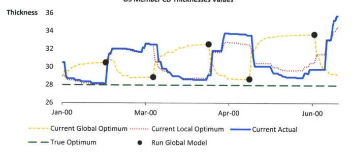
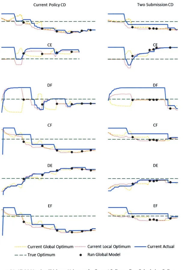
Figure 19: Changing Current Optima Drive Design Oscillation: Truss Member CE Thickness Values... 67
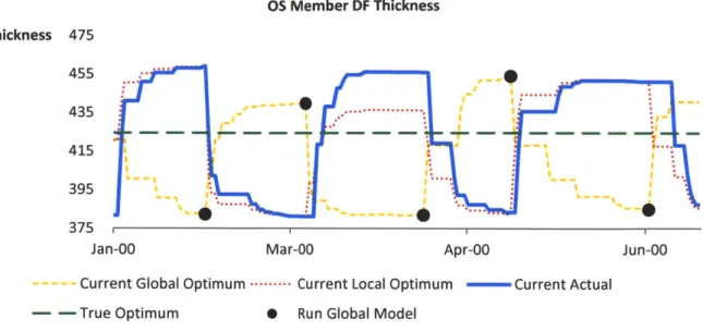
Figure 20: Changing Current Optima Drive Design Oscillation: Truss Member DF Values ... 68
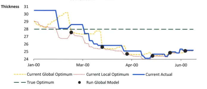
Figure 21: Changing Current Optima Drive Design Oscillation: Truss Member CD Values... 69
Figure 22: Safety Factors under Current Policy ... 70
Figure 23: Percent Difference from Optimal Loads under Current Policy ... 71
Figure 24: OS Member CD Thickness Values under Current Policy ... 72
Figure 25: All OS Member Thickness Values under Current Policy...72
Figure 26: Percent Difference from Optimal Mass under Current Policy ... 73
Figure 27: Effect of Global Model Run Policy on Mean and Standard Deviation of Time to Completion 74 Figure 28: Safety Factors under Two Subm ission Policy... 75
Figure 29: Percent Difference from Optimal Loads under Current Policy (Repeated) ... 76
Figure 30: Percent Difference from Optimal Loads under Two Submission Policy...76
Figure 31: All OS Member Thickness Values under Current Policy vs. Two Submission Policy ... 77
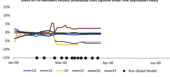
Figure 32: Safety Factors under One Subm ission Policy ... 79
Figure 34: Percent Difference from Optimal Loads under One Submission Policy... 80
Figure 35: All OS Member Thickness Values under Current Policy vs. One Submission Policy ... 81
Figure 36: Min Safety Factor to Submit vs. Time between Load Updates and Design Updates...82
Figure 37: Safety Factors with Minimum Safety Factor to Submit of 0.95... 83
Figure 38: Percent Difference from Optimal Loads under Current Policy (Repeated) ... 84
Figure 39: Percent Difference from Optimal Loads with Min Safety Factor of 0.95... 84
Figure 40: All OS Member Thickness Values under Current Policy vs. Lower Min Safety Factor...85
Figure 41: Min Safety Factor to Submit vs. Time between Load Updates and Design Updates...86
Figure 42: Safety Factors with Maximum Safety Factor to Submit of 1.15... 87
Figure 43: Percent Difference from Optimal Loads under Current Policy (Repeated) ... 88
Figure 44: Percent Difference from Optimal Loads with Max Safety Factor of 1.15... 88
Figure 45: All OS Member Thickness Values under Current Policy vs. Higher Max Safety Factor ... 89
Figure 46: Com parison of Policy Surface Charts ... 90
Figure 47: Results of Variable Safety Factor Thresholds under Three Submission Policy...91
Figure 48: Results of Variable Safety Factor Thresholds under Two Submission Policy...91
Figure 49: Results of Variable Safety Factor Thresholds under One Submission Policy...92
Figure 50: Safety Factors under Combined Policy Changes... 94
Figure 51: Percent Difference from Optimal Loads under Current Policy (Repeated) ... 94
Figure 52: Percent Difference from Optimal Loads under Combined Policy Changes...95
Figure 53: All OS Member Thickness Values under Current Policy vs. Combined Policy...96
Figure 54: Percent Difference from Optimal Mass under Current Policy (Repeated)...97
Figure 55: Percent Difference from Optimal Mass under Combined Policy Changes...97
Figure 56: Predicted Tim es to Acceptable and Final Designs...100
Figure 57: Predicted Individual and Team Sizing Loop Iterations...101
Figure 58: Acceptable Safety Factor Ranges in Pre-Game Survey Responses...102
Figure 59: Real-time Loads on Outboard Section Truss Members during First Round...106
Figure 60: Loads on Outboard Section Truss Members as Seen by OS SDP during First Round...106
Figure 61: Safety Factors of Outboard Section Truss Members during First Round...107
Figure 62: Outboard Section Member Thicknesses during First Round ... 108
Figure 63: Outboard Section Member Thickness Differences from Optimal during First Round...108
Figure 64: OS Member CD Thickness Values during First Round ... 108
Figure 65: All OS Member Thickness Values during First Round ... 109
Figure 66: Outboard Section Mass Percent Difference from Optimal during First Round...109
Figure 67: Section Design Players Underestimate the Effect of Their Changes on Other Sections...111
Figure 68: Loads on OS Members Percent Differences from Optimal during First Round...113
Figure 70: Outboard Section Safety Factors during First Round (repeated) ... 114
Figure 71: Safety Factors during Second Round ... 114
Figure 72: All OS Thickness Values First Round vs. Second Round ... 115
Figure 73: Outboard Section Mass during First Round ... 116
1 Introduction
This thesis examines product development in a large commercial aerospace program structured as an extended enterprise and explores strategies to accelerate product development in that ecosystem. While certain aspects of this ecosystem are unique to the commercial aerospace industry, many of the conditions that create a challenging product development environment for this program may be found in other industries that develop complex products and systems.
The aircraft program in question' is structured as an extended enterprise where first and second tier suppliers perform most of the detailed product development. Two of the program's primary objectives are to achieve unprecedented fuel efficiency relative to similarly sized aircraft and to significantly reduce development time. Several structural engineering challenges and unanticipated delays to the program's product development schedule have put these objectives at risk.
1.1
Objective
"Human performance in complex dynamic environments is poor relative to normative standards, and even compared to simple decision rules" (Sterman, 1994).
This thesis examines the hypothesis that the product development enterprise is misaligned with the product architecture and that intuitive development strategies in this environment generate some of the very undesired dynamic behaviors in the product development system they are intended to prevent. It explores the specific causes of observed dynamic behavior in the design process during which
suppliers and the original equipment manufacturer (OEM) fail to come to agreement on important design parameters that affect weight, structural loads, and the resulting internal stresses in the structure. In addition, it suggests alternate strategies for dealing with engineering design changes and presents a simulation game and agent-based model whereby it tests whether these strategies reduce the dynamically-induced delays.
1.2
Project Motivation and Hypothesis
This thesis research was conducted during a six-month internship as part of a partnership between Spirit AeroSystems and the MIT Leaders for Global Operations (LGO) program. LGO is a partnership between the MIT School of Engineering, the MIT Sloan School of Management, and several operations-focused companies from around the world. Its purpose is to discover the principles that produce world-class, operations-oriented companies and leaders, and to translate those principles into teaching and practice.
Spirit AeroSystems is currently engaged as a supplier of large carbon fiber composite airframe components to a major new aircraft program, with detailed design and manufacturing responsibility for structural fuselage and wing components. During the product development phase of engineering the first variant of this aircraft, Spirit's wing structure engineering team received several unplanned
updates to structural loads, requirements, and mandated analysis software tools from its OEM customer, which forced the team to perform significant engineering rework. One member of the
program management staff estimated the team had done the work of designing its components five to six times over, and Spirit's Program Manager for the wing structure components estimated that only one third of his team's engineering effort meaningfully contributed toward the final design, the
remainder being superseded by later rework. While this research was conducted primarily under the auspices of the wing structures team, leaders of the fuselage team participated in interviews and described similar symptoms. The extra time Spirit and other suppliers spent on rework driven by these and similar changes caused milestone deadlines to slip for the entire aircraft program and resulted in undisclosed millions of dollars in supplier claims against the OEM for compensation.
Spirit's team spent a significant portion of this rework in tasks within the structural sizing loop. The sizing loop is the process whereby members of the enterprise determine the components' proper geometries and thicknesses with the aim of supporting structural loads while minimizing mass. Since stress is load per unit area, larger or thicker structural elements reduce stress but increase component mass. The design process must resolve the obvious conflict between keeping mass low while keeping stresses within requirements. As each supplier makes design changes in response to implicit or explicit requests from the OEM to reduce either weight or stress, those changes affect the loads that each supplier's parts exert on other parts, requiring further adjustments to those parts' thicknesses. The tasks and the exchange of information to meet both stress and mass objectives are called the sizing loop. The Spirit team's engineering manager commented that "we expected two sizing loops and instead [there were] eight."
This thesis focuses primarily on the loads changes related to the sizing loop across the extended enterprise as a concrete and tractable example of how misalignment of product and enterprise architecture generates design oscillation. Other changes, such as changes to analysis software and high-level requirements also cause delays and rework; this thesis will not address them because their effects are very context-sensitive and explaining them would disclose proprietary information. At this internship project's outset Spirit's wing structures team members enumerated the
aforementioned symptoms and easily identified their proximate causes, but could not articulate a coherent theory of their underlying sources. Nevertheless, company experience with other aircraft
programs had convinced the team there were significant opportunities to accelerate the product development process for future variants of this aircraft.
Several past LGO theses have explored strategies to accelerate product development. These strategies have included the use of Design Structure Matrices (Rogers, 2009), simulation models (MacDonald,
2006; Mar, 1999), and analytical models (Bromberg, 2000), as well as case studies (Folgo, 2008;
MacDonald, 2006), and application of the theory of constraints (Cook, 1998). One previous work that pursues an approach similar to this thesis combines a system dynamics model and a board game replicating internal and external supply process for stamping die development at an automotive manufacturer (Kelly, 1996). The board game became a training tool to help the manufacturer's managers understand how to work more effectively in the complex, dynamic system of which they were a part.
Two other papers on related topics offer suggestions for managing the design of complex systems to accelerate design convergence. Mihm et al. study problem solving oscillations in a mathematical model of a theoretical complex design project, offering several insights into its behavior and suggestions to
improve its performance (2003). Braha and Bar-Yam study the statistical mechanics of information flow in product development networks (2007). Their conclusions suggest that improvement efforts focused on central information consuming and information generating tasks can drastically alter the network's
performance. Both of these works are addressed later in greater detail.
1.3
Hypothesis
As stated earlier, this work examines the hypothesis that in this program the product development enterprise is misaligned with the product architecture and that this misalignment generates undesired dynamic behaviors in the product development system.
This hypothesis is here broken in two:
* The sizing loop is analogous to a dynamic system with time delay.
* The theory of control of time delay feedback systems can be applied to the aircraft sizing loop
and doing so can result in fewer iterations of the sizing loop and faster convergence to a design that meets the conflicting goals of meeting stress requirements and minimizing mass.
1.4 Synopsis
This section presents a brief synopsis of the research and findings to act as a roadmap for the reader. The author first considers the nature of the studied composite materials aerostructures in light of
product architecture literature. This body of theory clearly indicates that the modern airframe, composed of many aerostructures, is an inherently integrated product. The process of developing
complex integrated products exhibits several well-known behaviors, such as iteration and cascades of changes in component designs. The author next evaluates the organizational structure of the product development effort, in the context of relevant literature, and demonstrates it is clearly more
decentralized than past programs for similar aircraft. This structure reduces and slows communication throughout the enterprise.
The combined behaviors of integrated product development and decentralized development efforts induce engineers to attempt to optimize component designs with each enterprise-wide design iteration. This both delays the sharing of design updates and causes higher amplitude changes to designs with each iteration. However, engineers underestimate how much changes to their
components affect the parameters for requirements that other components must meet. High amplitude design changes that alter loads on other components force further iterations, and delays make them take even longer.
With these issues in mind the author developed a simulation exercise game patterned after the basic problem structure that engineers in the aircraft program face. The game exists in two formats, one for human players and another for automated agent-based simulation. After interviewing Spirit engineers to ascertain the relevant current policies in the aircraft program, the author approximated these policies as decision rules in the agent-based simulation. Simulations with agents using these decision rules yields design oscillation that delays final product definition, as predicted by the theory.described in the previous paragraph. The author next tests the effects of three decision rule changes: more frequently running a global stress model that determines loads on components and separately relaxing the upper and lower constraints for suppliers to submit updated designs to the agent representing the OEM. Finding that each of these changes alone reduces the time to design convergence, the author testes the combined effect of all three changes and finds they consistently result in much earlier convergence.
The author next facilitated sessions of the game with senior engineers and program managers at Spirit. During the first round of the game the participants pursued their intuitive strategies, resulting in design and loads oscillation that delayed final design definition, the very phenomena that participants'
strategies were intended to minimize. After a debriefing and discussion, during the second round of the game participants implemented the combined decision rule changes described above. The results of the second round of the game confirm that these strategy changes significantly reduce design
convergence time similar to the agent model. These simulation outcomes illustrate that experts working on this problem under strategies intended to minimize development time and oscillation can actually increase these undesired system behaviors, but that alternative strategies can reduce such behaviors significantly.
1.5 Thesis Outline
This chapter has presented an overview of the product development challenges that the motivated this research and the hypothesis it examines. Chapter two orients the reader to the context in which these challenges arose. It provides background information about Spirit AeroSystems, describes important industry trends, and introduces concepts central to aerostructures and their development. Chapter three outlines the product development theory that defines the aircraft's airframe as an integrated
product and the program as relatively decentralized, and explains the system behavior implications of each architecture selection. Chapter four explains how the program's mismatch between product and enterprise architecture generates undesired oscillation in structural loads and designs.
Chapters five through eight describe the simulation exercise game used to explore the effects of the principles described in chapter four and the results and immediate implications of that exploration. It describes how the game is built to mimic important features of the airframe and the extended enterprise to generate similar behaviors. Chapter six explains how the author adapted the game to accommodate automated based simulation. Chapter seven summarizes the results of agent-based simulations exploring the impact of agent decision rules on the agent team's performance. Chapter eight describes the results of the game as played by experts and analyzes the players' apparent
mental models and gaps between those mental models and reality.
Chapter nine closes the thesis by summarizing the results of the game and their implications and by offering specific and general recommendations for developers of complex products and systems in extended enterprises. It also offers areas for further research.
2
Problem Context
This chapter orients the reader to the company, industry, and program context in which this product development effort occurred. It outlines several of the forces that shaped the environment in which Spirit's team worked and which contributed to the challenges it faced.
2.1
Company Context
Headquartered in Wichita, KS, Spirit AeroSystems, Inc. is the world's largest independent non-OEM
aircraft parts designer and manufacturer of commercial aerostructures2(Spirit AeroSystems, 2011). It
owns and operates manufacturing and assembly facilities in Wichita, KS; Tulsa, OK; McAlester, OK; Kinston, NC; Prestwick, Scotland; Saint-Nazaire, France and Subang, Malaysia (Spirit AeroSystems,
2011). Spirit's customers include Gulfstream, Mitsubishi, Bombardier, Sikorsky, Rolls-Royce, Hawker
Beechcraft, Israeli Aerospace Industries, Boeing, Airbus, the United States government, Cathay Pacific, Continental Airlines, American Airlines, and Southwest Airlines (Spirit AeroSystems, 2011).
Spirit AeroSystems is in the unusual position of being a five-year old company with eighty years of experience. Spirit's Wichita location began as the factory for Stearman Aircraft in 1927. Boeing
acquired Stearman in 1929, and the site grew into Boeing's Wichita Division. During World War 1l the
division produced the B-29 Superfortress and later the B-47 Stratojet and B-52 Superfortress aircraft. In more recent decades it served as the production site for many structural components of Boeing's commercial aircraft family. In 2005, Boeing Commercial Airplanes sold the Wichita Division, which included its Tulsa, OK and McAlester, OK sites, to Canadian investment firm Onex Corporation, which named the new company Spirit AeroSystems. In 2006, Spirit acquired BAE Systems' aerostructures business, converting it to a wholly owned subsidiary named Spirit AeroSystems (Europe) Ltd. Spirit first offered stock to the market in late 2006, though ONEX retains majority ownership of Spirit
AeroSystems Holdings, Inc.
Boeing was the only source of Spirit's revenue at the divestment. Since then Spirit has aggressively diversified its customer base so that its fortunes no longer depend any single other company. Most importantly, it has developed a significant business relationship with Boeing's primary competitor Airbus. 83% of 2010 revenues were from Boeing and 11% were from Airbus (Spirit AeroSystems, 2011). This puts Spirit in a well-hedged position in the jetliner business-if either of the Boeing-Airbus duopoly
pulls ahead, Spirit has a strong business relationship with the leader.
Spirit manufactures aerostructures for every Boeing Commercial Airplanes aircraft currently in production. It provides most of the airframe for the Boeing 737 jetliner. For the Boeing 787, Spirit
manufactures the forward fuselage, including the cockpit section, the wing leading edges, and the engine pylons. This work package makes Spirit the largest aerostructures supplier for the 787. With its addition of Spirit Europe, Spirit AeroSystems also became the largest independent
aerostructures supplier to Airbus. Spirit Europe manufactures components for the Airbus A320, A330, A340, A350, and A380 families.
2.2
Industry Context
The commercial airline industry is in rapid transition, shaped by a variety of forces such as increasing globalization of production and demand, growing demand for air travel, rising petroleum prices, and explosions of information technology for global collaboration. One important trend that is relevant to this thesis is the growth of extended enterprises, often termed risk sharing partnerships in the industry, to develop new aircraft.
2.2.1
Toward Risk Sharing Extended Enterprises
The enormous cost of developing large new commercial aircraft has begun driving OEMs toward outsourcing detailed design work to suppliers and asking them to take equity shares in the aircraft
program. OEMs generate design concepts and principles, then act primarily as integrators between the supplier teams developing detailed designs of the various systems and components. Embraer recently
implemented this strategy to develop and manufacture its ERJ-1 70/190 family of regional jets with great success reducing both development time and cost (Figueiredo, Silveira, & Sbragia, 2008). The two most prominent aircraft programs implementing the extended enterprise business model are the Boeing 787 and the Airbus A350 XWB. Both Boeing and Airbus have essentially announced intentions to become large scale systems integrators, though each intends to retain differentiating commercial aircraft capabilities. Airbus frames this as a focus on activities such as overall aircraft and cabin architecture, systems integration, and the development and testing of new technologies (Airbus,
2007). Boeing Commercial Airplanes intends to focus on its core capabilities in final assembly of
fuselage, interiors, and propulsion systems (Dustman, 2004).
At the outset of the 787's development effort, a Business Week article explained that "for the first time, with the 787, Boeing is outsourcing more than 70% of the airframe and is giving aircraft suppliers the responsibility for doing the detail engineering designs" (Holmes, 2006). The article offers several explanations for this departure from Boeing's traditional in-house design approach. First, and most apt to its name, the risk sharing partner model allows Boeing to spread the enormous cost of developing the aircraft across several companies. Instead of paying for development costs itself, Boeing offered its risk sharing partner suppliers an equity stake in the aircraft in exchange for paying development costs
themselves. Second, Boeing needed to locate some manufacturing work in countries such as China and India as part of offset agreements allowing it to sell airplanes in those quickly growing markets. In addition, outsourcing the design gave Boeing access to engineering labor beyond its own walls and helped improve design for manufacture. Mike Bair, the then program manager of the 787 also
explained that "one of the things we have found [is that] it's best to have the people building the parts designing the parts." Finally, choosing suppliers from around the world also helped hedge Boeing against the risks of currency fluctuations.
Airbus similarly outsourced roughly 50% of the A350 XWB aerostructures, about twice as much as in past programs (Airbus, 2007). In introducing Airbus' Power8 restructuring plan in 2007, CEO Louis Gallois said "We will turn Airbus into an extended enterprise. The A350 XWB will draw on this new business model, as we assign large work packages to Tier 1 suppliers in return for a better distribution of future investment, risks and opportunities, with a consolidated supply base" (Airbus, 2007). The
A350 risk sharing partnership is a smaller departure from tradition than Boeing's 787 approach. While A350 risk sharing partners also have equity stakes in each aircraft, Airbus also compensates supplier
partners at a roughly "break even" rate for development efforts, with periodic payments when the program reaches development milestones.
Despite high initial hopes, both the 787 and A350 have experienced setbacks that have delayed delivery to customers and caused both aircraft to fall short of intended performance. Boeing originally planned for the 787 to enter service in May of 2008, but at the writing of this thesis that had been pushed back to July 2011 (Ostrower, 2011). Aviationweek.com noted that "longer-than-anticipated design activities for the A350XWB twin widebody are forcing Airbus to delay the aircraft's final assembly start and first flight by several months" (Wall, 2010). Both aircraft have also been overweight at some point in their development; the first six 787 delivered are expected to be approximately 5,000 lb. above specifications and a June 2010 article put the A350 2.2 tons overweight (FleetBuzz Editorial, 2010). One Airbus supplier characterized the position the delays and excess mass have put them in:
"We can either aim to deliver on time and [it will] be overweight or be delayed and get the weight right. The longer we leave this, we'll be in the throes of ramping up production - there won't be enough resources to dedicate to that [production ramp-up] and deal with the weight" (FleetBuzz Editorial, 2010).
Both programs face difficult choices as they try to reduce mass while making up for lost time to deliver to their customers.
2.3
Aircraft Program Context
This section briefly describes the relatively new business model that characterizes the relationship between the OEM and its suppliers for this program, and the program's overall objectives.
2.3.1
Risk Sharing Partnership
The aircraft program studied for this thesis is structured as an extended enterprise of several well-known aerospace suppliers from around the world working under the leadership of the OEM. The OEM acts as an integrator and hub for interfacing partners to share information and coordinate their development efforts. In fact in this program, the OEM has discouraged suppliers from collaborating directly with one another, encouraging them instead to use the OEM as an intermediary. As will be discussed later, this may stem from a desire to protect proprietary information between suppliers who compete on other programs and to prevent suppliers from gaining the institutional knowledge to eventually displace the OEM. Some Spirit personnel also theorized this was an approach to maintain schedule pressure on all suppliers by preventing "fast" suppliers from learning of delays at others. But as the reader shall see, this may be a prime cause of the delays discussed in Chapter 1.
2.3.2
Program Objectives
The program studied for this project has two primary objectives that are relevant to this research. First, the OEM seeks to develop an extremely fuel efficient aircraft to meet airlines' demand for more fuel efficient fleets. Second, the OEM seeks to bring the aircraft to market quickly. Many airlines are rumored to be deciding between this aircraft and a direct competitor; delivery date and operating costs, driven by fuel efficiency, are two of the most important dimensions they will consider. Aging long-range fleets and rising petroleum prices have generated intense airline interest in
lightweight long-range aircraft. A January 2009 Seattle Post-Intelligencer article observed that "airlines hoping to save on fuel bills are eagerly awaiting both the 787 and the A350. Both models are designed to be more energy-efficient than aircraft flying today thanks to a greater use of composite carbon materials" (Vandore, 2009). In addition to its unprecedented use of composite materials, the program has aggressively sought to optimize every possible aspect of the design to safely eliminate excess mass. For example, the OEM has insisted that at each phase of development efforts, risk sharing partners submit highly optimized designs that minimize mass while still meeting stress and other design
requirements. Later discussion will outline the many ways that aircraft mass influences airline operating costs and other costs.
A second primary objective is to minimize development time. There are at least three key reasons the
OEM seeks to develop the aircraft quickly. The earlier the OEM can promise delivery to its customers, the better its position to gain market share against competing aircraft. Further, the sooner the OEM
can begin delivering the aircraft to its customers, the sooner it can begin to recoup the enormous cost of product development and capital outlay for manufacturing equipment. Finally, if the program is delayed, the OEM incurs significant penalties for late deliveries to its customers.
2.4 Aerostructures in the Aircraft
The components at the focus of this research are aerostructures. These are components that make up the airframe of the aircraft, especially the fuselage and wing. Their primary function is to collectively bear the structural loads on the aircraft in all operating conditions. In this function components transfer loads one to another at their interfaces. This means that each aerostructure must be designed with an understanding of the loads that interfacing aerostructures will exert on it.
Some aerostructures perform dual functions. For example, in addition to bearing loads, wing
aerostructures form the aircraft's most important aerodynamic surfaces and often constitute the fuel tank. The optimal design for one of these functions is rarely the optimal design for another; often the best design for one role is not even feasible for another. Engineers for such structures must therefore generate designs that perform acceptably across all functions' performance parameters.
2.4.1
Composite Aerostructures
The main source of weight savings in this aircraft is the use of composite materials, such as carbon fiber reinforced polymers, in its aerostructures. Earlier generations of commercial aircraft have used
composite materials but never to the degree the current generation uses them. This introduces new opportunities and constraints that reshape the design space for the aircraft. While composite materials' high strength-to-mass ratios make them attractive options for reducing mass, other properties add significant challenges to producing composite material structural parts.
First, the technologies to design, manufacture, and test composite materials are still maturing. Companies using these technologies have learned many lessons during product development for mostly composite aircraft, some of them very publicly. For example, Boeing's 787 engineers discovered late in its design process that earlier plans to dissipate electrical charges from lightning strikes were insufficient. Metallic airframes conduct electricity while composite materials insulate against it. In a composite aircraft, lightning would seek a path through the aircraft's few metallic parts like fasteners, hinges, and wiring. Such small parts would likely fuse or vaporize, and the possibility of fuel ignition had been raised. The 787 program had to make compensating changes, adding approximately five thousand pounds to the aircraft's mass. This required significant engineering rework to make the
changes themselves and to make accommodating changes elsewhere. The Airbus A350 XWB also made late changes to fastener requirements to manage similar lightning strike risks.
To manufacture composite aerostructures, strips or sheets of composite material are layered on a precisely engineered metal tool and then cured in an autoclave. After curing, composite components can be trimmed and drilled but their shape and thickness are fixed. The curing process generates residual stresses that cause the component to deflect from the shape in which it was cured. Because these deflections can exceed dimensional tolerances, they must be accurately anticipated and
counteracted in the tooling geometry. While the corresponding manufacturing processes for metallic parts also generate residual stresses and deflections, the technology to anticipate and counteract these effects is quite mature while analysis methods for composite material deflections are still in their infancy.
Earlier aluminum aircraft often began production with the intention of continuing engineering improvements to be incorporated in later production units. According to experts at Spirit, any change in composite component geometry or thickness is likely to affect the residual stresses from curing and thus affect the tooling design. Because these tools are expensive and difficult, if not impossible, to modify, this raises the stakes for making engineering changes to the component after tooling has been built. Since finished tooling is essential for production, this links development delays rather firmly to production and aircraft delivery delays.
2.5
Balancing Stress and Mass
Two of the most important product characteristics aerostructures engineers must balance are stress and mass. This section introduces the reader to the role they play in aerostructures and the method by which engineers in the enterprise balance the two to optimize aerostructure performance.
2.5.1
Mass and Aerostructure Design
As petroleum prices have risen steeply throughout the past decade, fuel efficiency has become drastically more important to airlines because fuel represents an increasing proportion of operating costs. In response, aircraft OEMs have sought to significantly reduce airframe mass. Reducing airframe
mass allows the plane to either carry more fuel, increasing its range, or to carry more passengers or cargo; either adds to airlines' revenue. While composite materials provide substantial strength-to-mass advantages over aluminum, manufacturers must still aggressively eliminate excess mass wherever possible to meet current airline expectations.
When airlines commit to purchase aircraft they incorporate contract clauses regarding target mass to offset the costs of excess mass. If the delivered aircraft exceeds this target mass, the airline is entitled to assess penalties against the OEM in proportion to the overage, and these mass targets cascade into supplier contracts. In its request for quote (RFQ) documents sent to potential suppliers, the OEM proposes a mass target for the component in question, as well as targets for price and delivery dates.
Proposed mass targets are estimates based on mass distributions in similar metallic aircraft. However, with the new opportunities and constraints of composite materials, there is no guarantee the ideal distribution will remain the same for all components. Contract targets are negotiable, but constitute
primary performance measures by which the OEM evaluates bids, so suppliers are reluctant to revise them upward.
Aerostructure supply contracts include penalty and incentive clauses tied to component mass. If the supplier delivers a component that exceeds agreed target mass, it is subject to a significant penalty
proportional to the overage. If the component is significantly overweight, the penalties could be large enough to eliminate the supplier's profit for that part. Similarly, when the supplier delivers a
component weighing less than the target mass, it receives an incentive payment proportional to the mass savings. Penalties per unit of mass are typically much higher than incentive payments per unit mass.
Excess mass also adds to supply chain costs and airport landing fees. Airport companies charge fees to land airplanes at their airports, and the fees depend in part on mass, with heavier airplanes incurring larger fees. Excess mass in the design is also excess material which must be purchased, and composite material is very expensive. In composite material designs, excess material must be laid ply-by-ply on molding tools, tying up extremely capital-intensive equipment. The excess mass must also be shipped throughout the supply chain, adding to total production costs. These factors add to the pressure for suppliers and the OEM to reduce mass.
2.5.2
Stress and Aerostructure Design
In order to fly safely, and to receive flight certification from regulatory agencies such as the US Federal Aviation Administration or the European Aviation Safety Administration, airframes must be engineered to ensure the structure is strong enough to withstand all the loads they must bear. The loads on a component, combined with its geometric and material strength properties, determine the stress in each
part of the component. If stress in any component is too high, the component will fail.
Safety factors, sometimes called design factors or reserve factors, are an important set of metrics in structural engineering, including for aerostructures. These values give the ratio of allowable stress
divided by actual or calculated stress. For example, if the heaviest loads on a component are expected to create 100 units of stress, requirements might call for a safety factor of 1.5, meaning the design
must withstand 150 units of stress. If the calculated stress exceeds the allowable stress, the safety factor will fall below the required safety factor, while if the allowable stress exceeds the calculated stress, the safety factor will be above its target value. Safety factors below the target value are
bear. On the other hand, safety factors above the target value indicate excess material that decreases fuel efficiency without adding structural value. In practice, engineers often treat the safety factors of areas within each component as a proxy metric to identify and quantify excess mass.
Target safety factors can vary such that some loads and components might require safety factors of 2.0
while others might require 1.5. For simplicity and clarity, this thesis normalizes safety factors to 1.0 so
that a safety factor of 1.0 represents the condition where the maximum allowable stress per the requirement is equal to the calculated stress at the point in question. This means that in all discussions of the sizing loop, the ideal safety factor for any component is 1.0.
2.5.3
The Sizing Loop
As noted earlier, Spirit's team spent much of its rework effort in the sizing loop tasks to determine the proper geometries and thicknesses to balance stress and mass in their component. The design thickness determines the number of composite material plies to be laid on one another and cured to form the
part. The term sizing loop is used because these tasks form a goal-seeking feedback loop whereby the
program attempts to meet stress requirements with minimum mass, generally using safety factors as a metric of optimality.
The sizing loop process begins when the OEM incorporates design updates from suppliers into its global finite element model for stress analysis of the entire aircraft or for a large section such as the wing. By evaluating the finite element model against the structural loads applied to the overall aircraft, the OEM determines the loads applied to each component. While the external environment applies some of the loads, many of them are called interface loads because they transfer from one airframe component to another at the interface between the two. Ribs in the aircraft's wing, for example, only experience loads as exerted on them by neighboring components and not from external air pressures. Figure 1 shows the tasks in the sizing loop. The sizing loop is actually two sizing loops, one inside the other. The inner loop, labeled the supplier sizing loop, occurs at the supplier stress team level consists of adjusting thicknesses to balance stress and mass given the most recently delivered interface loads; the dashed green line shows the path of tasks and decisions in this loop. The outer loop, labeled the enterprise loop, treats design updates from suppliers the same way suppliers treat thickness changes for their components; the dashed blue lines show the tasks and decisions for this loop. Design changes feed into the global finite element model to evaluate how well the current designs collectively meet overall stress and mass requirements.
Figure 1: The Sizing Loop
After running its global finite element stress model, the OEM notifies suppliers of updated load sets for each component. Each supplier then downloads the updated loads data and converts it into a format appropriate for its local finite element stress analysis tools. Then the supplier team incorporates the new loads in a local stress model, which it uses to evaluate and adjust its design. Running the local stress model typically requires a few hours and engineers receive reports of safety factors after the full analysis is complete. Supplier engineers use safety factors as a direct measure of whether the design meets stress requirements and as a proxy measure for whether there are areas with excess mass. Accordingly, they add material to areas with safety factors below 1.0 and may remove it from areas with safety factors above 1.0 in an effort to reduce mass, then run the local stress model again. The follow this process until all safety factors fall within upper and lower safety factor thresholds. When this design update is complete the supplier submits its updated design to the OEM for the next sizing loop iteration.
Engineers at Spirit said the lowest allowable safety factor in a submitted design at any phase of the detailed design process is 1.0, meaning all parts of the design meet minimum stress requirements. The
upper threshold is between about 1.05 and 1.10, reflecting an aggressive goal to minimize excess material in any part of the component design. If designs meet these requirements before milestone deadlines engineers typically continue optimizing the design to remove excess mass. Spirit engineers indicated that this approach reflects the program OEM's expectations, and also matched engineers' practice at Spirit for other programs and aerospace engineering practice in general.
Figure 2 shows a causal loop diagram explaining how stress and mass create conflicting goals and requirements. Plus signs next to arrows indicate a direct causal relationship-if the cause parameter increases the effect parameter does as well-while minus signs indicate inverse relationships. Causes and effects with variable relationships are unsigned. Hash marks indicate delays which are explained by nearby italic text.
Material Strength
Strength
-S Shortfall Amount above
Stress+nt/e Mass Target Requirement/ + Mass Target Stress - Thickness + Thickne+ Mass Load on Component Loads on Other
Thickness of Other Components
Components
SStress in Other
0 h Components
Figure 2: Stress and Mass Create Conflicting Goals
While information about the supplier-level sizing loop process at others suppliers was not available to the author, it is reasonable to presume that other suppliers and teams followed a similar one. To the Spirit team's knowledge the OEM set a cadence, about once a quarter, for all supplier teams to regularly submit their updated designs to its central database. When all teams have submitted their designs, the OEM runs its global finite element model. This generates an updated set of loads on each component that the OEM distributes to suppliers for the process to begin again. The OEM chose its cadence of once a quarter to give suppliers sufficient time to update designs to meet requirements and
mass expectations before a new set of loads arrived. While the enterprise's expectation was that these loads would stabilize, with smaller changes in each iteration, many loads oscillated more than expected even late in the program.
At first blush one might assume that the several changes to the structural loads on Spirit's component were driven by changes to external structural loads on the airframe, but they were not. In a group
interview, several engineering leads at Spirit observed that "overall [aircraft] loads are generally stable and converged quickly...but interface loads are much less mature." They essentially meant that even though all the forces acting on the airframe were well-defined early in the development process, the
distribution of those forces throughout the airframe's components still oscillated even late in the development process. This happened because this distribution of forces both affects and is affected by the ongoing changes suppliers make to component designs in trying to meet stress requirements and
mass targets. These design changes change the loads between components without affecting overall loads on the aircraft. Such oscillation in a system with stable external inputs suggests it might be treated as a dynamic system with time delays.
2.5.4 Loop Gain
Control theory describes how dynamic systems with time delay are managed to achieve desired outcomes. Under control theory, goal-seeking negative feedback loops like the sizing loop either periodically or continuously compare a system's current output against its desired output, sending a control signal to the system to adjust system parameters to decrease the gap between the current and target output, often in proportion to the size of the gap. The enterprise sizing loop periodically samples
its output by running the global finite element model, and the suppliers' sizing loops sample their outputs by running local stress models.
The parameter that determines the relative amplitude of the control signal, is the loop gain and ranges
from 0 to 1.0. A system with high loop gain adjusts its state toward its target state more quickly or forcefully than a system with low loop gain. In the sizing loop the intuitively attractive loop gain is 1.0,
meaning that engineers want to immediately remove all the discrepancy between current designs and the ideal design. According to interviews with Spirit engineers, loop gain is high in both the enterprise and supplier sizing loops. Spirit engineers make changes intended to bring safety factors as close to 1.0 as possible in each iteration of the supplier sizing loop, indicating high loop gain, and other supplier engineers likely do the same. Similarly, each supplier tends to iterate through the supplier sizing loop until the component design both meets stress requirements and is relatively optimized for mass as measured by the safety factor parameters discussed earlier. Currently suppliers aim to submit designs with all safety factors above 1.0 and below 1.05 or 1.10.
OEM expectations reinforce this aggressive standard. Its general policy is to run the global finite element model quarterly, with the expectation that after receiving loads updates, suppliers optimize designs to this standard in that time before submitting them. One might presume that the time to run the global finite element model might be a limiting constraint, either that it was already being run as frequently as possible or that resources to run it were so expensive it was desirable to minimize
iterations. According to an email from an OEM representative, neither is true. In fact, the OEM indicated that its finite element model can typically provide results within a matter of hours. The
primary reason for quarterly sizing loop iterations is instead a fear of injecting chaos into the process by
releasing new load updates before suppliers have finished updating designs in response to the most recent set. This philosophy is consistent with Braha and Bar-Yam's observation that designs fail to converge when the rate at which tasks are affected by neighboring changes exceeds the task's internal completion rate (2007).
2.6 Summary
This chapter has introduced the context in which the symptomatic design and problem solving
oscillations occurred. The aircraft program studied fits an increasingly common business model of risk-sharing extended enterprise partnerships for new aircraft product development that effectively
decentralize product development effort across several firms. In addition, the program aggressively seeks to improve the aircraft's fuel efficiency while quickly bringing the aircraft to market. The chapter reviewed several important challenges of working with new composite materials technology and outlined the method by which aerospace engineers attempt to balance between stress requirements and the goal to minimize mass.
The following two chapters discuss what these facts say about where the airframe and the enterprise fit within the frameworks of product development and enterprise architecture theory. Chapter three presents the relevant product development theory and identifies the spaces the product and enterprise occupy in their respective architectural dimensions. With this identification it also describes recognized behaviors associated with products and enterprises occupying similar positions. Chapter four explains how the enterprise architecture is misaligned with the inherent product architecture, and how the combined behaviors of each can be expected to generate the symptomatic design and problem solving oscillations.
3
Misalignment of Product Architecture and Enterprise Architecture
This chapter introduces theories of product and enterprise architecture and characterizes the airframe and enterprise in the relevant dimensions of each. It explains behavioral characteristics of the product and enterprise architectures in use for the program, with anecdotal illustrations of the same.
3.1
Product Development Tradeoffs
In product development there is a well-recognized tension between product performance, development time, and development cost. The developing company or enterprise's capabilities, combined with the available technology, define a frontier of performance in these dimensions and programs trade
performance in each dimension on that frontier. Balancing these kinds of performance is a common source of tension between program management and engineers because each group tends, because of its domain knowledge and responsibilities, to focus on one or two more than the other.
Schedule pressures motivate the enterprise to finish design definition quickly and the cost of tooling motivates it to avoid later design updates. At the same time, the need for an optimized design that meets a difficult and conflicting set of stress and mass requirements drives the enterprise to keep trying to get a better solution. In this case, the need for refinement has won out so far and the schedule has slipped significantly. In the words of one advisor to this thesis, "Engineers want it better. [Program]
managers want it Friday. As long as there are iterations, engineers will try to make it better and Friday will never come."
The product and enterprise architectures implemented to develop the aircraft strongly influence product performance and the cost and length of development. In general, integrated product architectures and enterprise architectures offer better product performance, while modular
architectures offer shorter development time and lower cost. Product architecture also influences the appropriate management style. Ulrich and Eppinger assert that in the detailed design phase, managers of modular products should be most concerned with "ensuring that the teams assigned to chunks
[modules] are meeting the performance, cost, and schedule requirements for their chunks" while managers of integrated products must focus more on integration, conflict resolution, and coordination (2004). Anecdotal evidence suggests that the OEM's management style for this program more closely matches Ulrich and Eppinger's prescription for modular products than their prescription for integrated ones; Spirit interviewees described an intense OEM focus on component performance, cost and
schedule requirements and comparatively less focus on resolution of conflicts between component designs.
A mismatch between the product architecture and the product development enterprise architecture
modular products might end up costing more than necessary while still taking a long time. Extended enterprises developing inherently integrated products are likely to face delays and cost overruns as they try to bring product performance to acceptable levels. The latter scenario matches the symptoms of the case at hand.
3.2 Airframe Product Architecture
Product architectures define how a product's functions are allocated among its components.
Architectures are typically defined along a spectrum from highly integrated to highly modular. Modular architectures discretely allocate functions among components, while components in integrated
architectures share functions or perform dual roles (Ulrich & Eppinger, 2004). When components perform multiple functions they must balance between the performance attributes associated with each role they perform. When they share roles with other components, the shared performance attributes must be managed jointly to achieve an efficient design.
Components that share functions are coupled at their interfaces. Ulrich defines coupled components as those where a change to one will likely require a change to the other (1995); another term for coupling is interdependence. Airframe components are inherently coupled because loads transfer across
aerostructure interfaces in both directions. To be fair, some components bear more of certain loads than others, but components' responses to loads cannot be perfectly isolated and prevented from propagating part of the load to neighboring components. Like other primarily mechanical systems, the fact that each side of the interface must thus be matched to the energy transfer across the interface inherently limits the degree to which modular airframe architectures are feasible (Whitney, 2002). Further, the load interactions between components are complex and nonlinear, and therefore difficult to predict or characterize simply, making the airframe system a complex one.
Compared to many other products, modern airframes are highly integrated products-aerostructures are hardly off-the-shelf components. The question here is the degree of integrality relative to other
commercial aircraft. Modern large commercial aircraft follow the same general architecture and divide
functions among recognized sets of components in similar ways. They are modular to the degree that the principles that apply to designing major systems like wings, fuselages, or empennages hold from aircraft to aircraft. Using new composite materials technology changes the rules of the design game enough that many longstanding principles no longer apply and new ones crop up, suggesting a more integrated approach than for other aircraft would be appropriate.
The degree of performance optimization required also affects the degree of product integrality. Where complexity and coupling determine the number of interdependencies that exist between components, the pressure to optimize holistic product performance characteristics like fuel efficiency determines the