OATAO is an open access repository that collects the work of Toulouse
researchers and makes it freely available over the web where possible
Any correspondence concerning this service should be sent
to the repository administrator:
[email protected]
This is an author’s version published in:
http://oatao.univ-toulouse.fr/25560
To cite this version:
Bonfils-Lahovary, Marie-Laëtitia de
and Laffont, Lydia
and Blanc, Christine
Characterization of intergranular corrosion defects in a 2024 T351 aluminium alloy.
(2017) Corrosion Science, 119. 60-67. ISSN 0010-938X
Characterization of intergranular corrosion defects in a 2024 T351
aluminium alloy
Marie-Laetitia de Bonfils-Lahovary, Lydia Laffont*, Christine Blanc
Université de Toulouse, C/RIMAT, CNRS/ /Nf'T / UPS, ENSIAŒT, 4 allée Emile Manso, BP44362, 31 030 Toulouse Cedex 4, France
ARTICLE INFO ABSTRACT
Keywords: lntergranular corrosion defects formed after a 24h immersion in a 1 M NaCI solution in a 2024-T351 Al alloy were characterized using a combination of electron microscopy techniques. Results showed the dissolution of intergranular Cu-rich precipitates ail along the corroded grain boundaries. Cu species were incorporated inside the amorphous alumina oxide film identified in the corroded grain boundaries leading to the formation of structural defects in the oxide film. A 10-200 nm-thin metallic Cu-rich layer was also observed at the oxide{metal interface and at the tip of the intergranular corrosion defect. A Aluminium A.Copper A lnterrnetallics B.TEM C. lntergranular corrosion
1. Introduction
The 2024 Al alloy (AA2024) is widely used in aerospace indus
tries due to its high strength to weight ratio, its high mechanical
properties resulting from alloying elements such as copper
(1,2)
.
However, alloying elements generate a heterogeneous microstruc
ture Jeading to an increase of the susceptibility of the alloy to
localized corrosion such as intergranular corrosion.
Many studies in the literature have been carried out to increase
the understanding of the intergranular corrosion mechanisms
in AA2024. Usually, these mechanisms are described as a gal
vanic coupling between intergranular Cu-rich particles (0-Al
iCu;
S-Al
iCuMg) and the adjacent matrix (3-6). However, some authors
have shown that precipitate-free grain boundaries are also suscep
tible to intergranular corrosion suggesting that other parameters
as grain stored energy have to be taken into account (7,8).
Nevertheless, Cu-rich particles play a predominant rote in the
2XXX alloys intergranular corrosion susceptibility. The precipita
tion of such particles at the grain boundaries Jeads to a depletion
of some alloying elements on both sides of the grain boundaries.
Depending on the metallurgical state of the alloy, this can Jead to
the formation of a precipitate free zone (PfZ) surrounding the grain
boundaries and increasing the susceptibility to intergranular cor
rosion of these alloys. The electrochemical characteristics of the
* Corresponding author.
E-mail address: [email protected] (L Laffont). http://dx.doi.org/ 10.1 Ol 6/j.corsci.2017 .02.020
Cu-rich intermetallic phases, and mainly S-AliCuMg, have been
widely studied
(7-18)
. Authors assumed a mechanism based on
the strong reactivity of the partiel es that led to a Cu-enrichment ail
along the corroded grain boundaries when the alloy was exposed
to an aggressive solution. Such a Cu-enrichment ail along the cor
roded grain boundaries may have a strong effect on the progress
and kinetics of the intergranular corrosion defects
(7-9)
. There
fore, it is of great interest to have an accurate description of the
intergranular corrosion defects.
However, because of the difficulty in analyzing the grain bound
ary oxide films, the main part of the studies concerned Al-Cu model
alloys with various Cu contents
(17-33)
. Authors have character
ized the oxide films formed on these model alloys and identified
a thick uniform layer composed of alumina with the presence of
a 2-20 nm thin Cu layer at the interface oxide/AI alloy
(21-25)
.
Garcia-Vergara et al. proposed growth models of the Cu-enriched
layer with increasing thickness of the anodic film on an anodized
Al-0.4 at.% Cu model alloy
(20)
. One of the models is based on the
growth of Cu-rich clusters in the oxide film and was observed for
other Al-Cu model alloys with various Cu contents
(22)
. Zhou et al.
have also analyzed the anodic film formed on an Al- 2 wt.% Cu alloy
and found copper species as Cuo
(25)
.
While the nature of the oxides formed inside the intergranu
lar corrosion defects for industrial alloys was assumed to strongly
influence the intergranular corrosion propagation kinetics
(7-9)
,
it was not precisely characterized in terms of microstructure and
structure due to the thickness of the oxide layer formed which
required to use specific sample preparation and high resolution
analytical techniques. Comparison with the results obtained for model alloys seems relevant but this deserves to be proven due for example to the formation of a confined electrolyte inside an inter-granular corrosion defect which did not exist on the plane surface of a model alloy and might affect the electrochemical processes. In the present work, the intergranular corrosion defects formed for a 2024-T351 Al alloy after a continuous immersion in a 1 M NaCl aqueous solution were characterized. Results were compared to lit-erature data concerning the oxide layers formed on Cu-rich model alloys. A combination of Focus Ion Beam (FIB) technique, Transmis-sion Electron Microscopy (TEM) observations, Energy Dispersive X-Ray spectroscopy (EDX) and Electron Energy Loss Spectroscopy (EELS) analyses was used to characterize accurately both the mor-phology and chemical composition of the intergranular corrosion defects.
2. Experimental procedure 2.1. Material
The material used for this study was a 2024-T351 Al alloy (AA2024-T351) provided by Airbus Group (France). It was received as a 50 mm thick plate formed by hot rolling and followed by solu-tion heat treatment at 495◦C (± 5◦C), water quenching, straining
and tempering in ambient conditions for 4 days to achieve the final −T351 metallurgical state. Its composition is Al base, 4.46% Cu, 1.44% Mg, 0.60% Mn and 0.13 Fe, wt.%. The microstructure of this alloy corresponds to grains highly elongated in the rolling direction (L) with the average sizes of 700, 300 and 100m in the longitu-dinal (L), long transverse (LT) and short transverse (ST) directions, respectively[34,35].
2.2. Corrosion tests
Intergranular corrosion defects were formed following a 24 h continuous immersion of AA2024-T351 in a 1 M NaCl aerated solu-tion at room temperature (25◦C)[5,34,35]. Only the LT-ST faces of a 1 cm3 cubic sample were exposed to the NaCl solution, the
other faces being protected by a transparent lacquer, to promote the propagation of the intergranular corrosion along the L
direc-tion[36,37]. Before exposure to the NaCl solution, the sample was
abraded using SiC papers down to 5m, then polished down to 3m using diamond paste with distilled water as a lubricant. The sample was finally air-dried before being prepared for TEM obser-vations. Some polished samples (S = 1 cm2) were embedded in an
epoxy resin to perform electrochemical tests. The experimental set-up consisted of a three-electrode cell, connected to a Biologic VSP apparatus, with a large platinum electrode used as counter electrode and a saturated calomel electrode (SCE) as reference elec-trode. The corrosion potential (Ecorr) was measured for 24 h during
exposure of the sample to the 1 M NaCl solution. For the polariza-tion curves, the samples were first exposed to the electrolyte at Ecorrfor 1 h and then the anodic and cathodic parts were obtained
independently from Ecorrat a potential sweep rate of 0.07 mV s−1.
2.3. Characterization of the intergranular corrosion defects: preparation of the samples and description of the techniques
In order to obtain a thin sample in a localized region, i.e. in an intergranular corrosion defect, the preparation was done using con-ventional lift out procedure using a FEI HELIOS Nanolab 600i dual beam FIB/Scanning Electron Microscope (SEM); this is summarized in the supplementary material. A transparent section was obtained. Some intermetallic precipitates were visible inside and all around the intergranular corrosion defect in agreement with literature data
[5–7].
TEM and Scanning Transmission Electron Microscope (STEM) observations were recorded on a JEOL ARM 200F operating at 200 kV and equipped with a Schottky FEG, a Cs-corrector of the probe, a Gatan Imaging Filter (GIF) QUANTUM spectrometer. LAADF-STEM (Low Angle Annular Dark Field) images are dominated by diffraction contrast. In order to take into account the structure of the corrosion defects, the diffraction patterns were obtained using the Selected Area Electron Diffraction (SAED) mode or by Fourier transform of the HRTEM (High Resolution TEM) images. STEM/EELS analyses were performed with a probe size of 1 Å, an illumination semi angle of 14.8 mrd, a collection semi angle of 19.5 mrd and an energy dispersion of 0.1 eV/channel. Reference EELS spectra of CuO, Cu2O, alpha and/or gamma and/or amorphous Al203were recorded
in the same conditions as those used for analyzing the samples.
3. Results and discussion
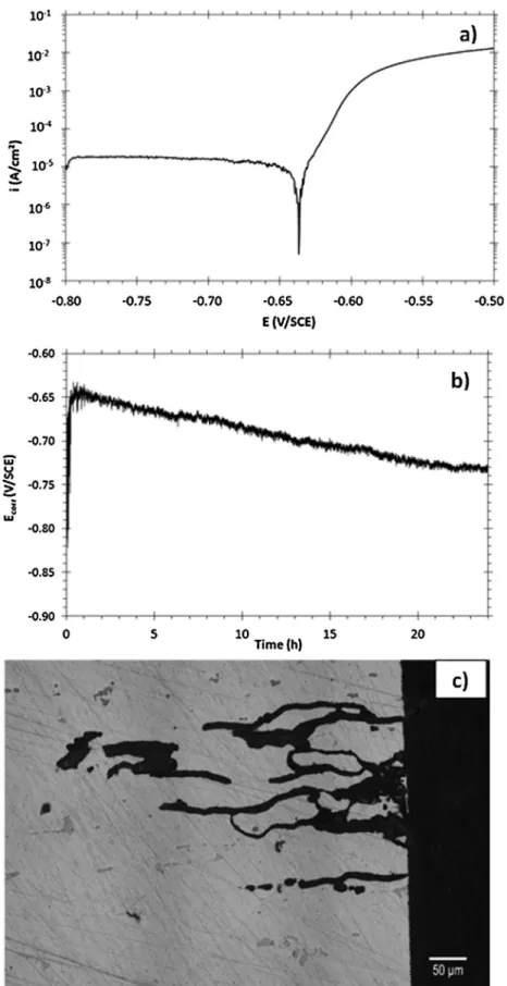
Fig. 1shows a polarization curve (Fig. 1a) plotted for the AA2024
sample in 1 M NaCl solution: a sharp increase of the anodic cur-rent densities after the corrosion potential (Ecorr) confirmed that
the alloy was susceptible to localized corrosion at Ecorr in such
an electrolyte. OM observations (not shown here) of the samples after the polarization test showed both pitting and intergranular corrosion. Therefore, we chose in this study to develop intergranu-lar corrosion defects by performing continuous immersion tests at
Ecorr.Fig. 1b shows Ecorrversus the exposure time to 1 M NaCl
solu-tion: a continuous decrease of Ecorrwas observed in agreement with
the propagation of corrosion defects.Fig. 1c shows, as an example, intergranular defects grown after a 24 h exposure at Ecorr in 1 M
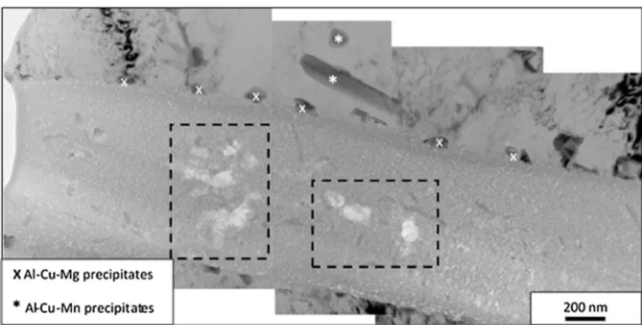
NaCl. TEM observations of these intergranular corrosion defects were performed for 3 FIB samples. Depending on the sample, several intergranular corrosion defects were present and character-ized. Given that the general features observed were similar for all samples, we present here only results for one intergranular corro-sion defect, for brevity.Fig. 2shows a photomontage of TEM images of an intergranular corrosion defect of an AA2024-T351 sample exposed to a 1 M NaCl solution during 24 h and removed by using a FIB/SEM.
The defect is approximately 1m wide and decorated by a chain of precipitates. EDX analyses allow to identify two types of precipi-tates: Al-Cu-Mg (80% Al− 17% Cu − 3% Mg, at.%) and Al-Cu-Mn (75% Al− 14% Cu − 11% Mn, at%). The presence of such precipitates was in agreement with literature data concerning the metallurgy of 2XXX alloys and the intergranular corrosion mechanism which attributes the susceptibility to intergranular corrosion of 2xxx alloys to the decoration of their grain boundary network with precipitates such as S phases (Al2CuMg) or phases (Al2Cu)[3–6]. Usually, the
inter-granular corrosion initiation is explained by a galvanic coupling between S and Cu-rich phases decorating the grain boundaries and the adjacent matrix.
Observations also showed that the intergranular corrosion defect was completely filled with corrosion products which most probably corresponded to alumina. In addition, white flaws were observed inside the intergranular corrosion defect (black dashed squares inFig. 2). They could be compared to those observed by Thompson et al. in their studies about anodization of Al-Cu model alloys, the authors describing the flaws as the results of an oxidation of Cu-rich impurities[23–26,38,39]. According to these authors, when an Al-Cu model alloy was anodized, Al was first oxidized due to the less negative Gibbs free energy per equivalent for the formation of copper oxide compared with that of alumina. This led to the formation of a few nanometers thick Cu-enriched layer at the interface alumina/model alloy inside the alloy. Inside this thin layer, Cu-rich precipitates, namely’ phases, were formed, their size depending on the interfacial coherency between the
alu-Fig. 1. a) Polarization curve of the AA2024 sample in a 1 M NaCl solution, b) Ecorrversus the exposure time to 1 M NaCl solution, c) Optical micrograph of intergranular corrosion defects formed after a 24 h exposure at Ecorrin a 1 M NaCl solution.
minium matrix and the Cu-rich layer[24]. Oxygen gas bubbles generated by the oxidation of Cu from these precipitates led to the formation of flaws inside the oxide film, similar to those observed in this study (black dashed squares inFig. 2)[32]. The presence
of such flaws inside the intergranular corrosion defect formed for the industrial alloy suggested that the electrochemical processes occurring during the corrosion of the grain boundaries were sim-ilar to those observed during the anodization of an Al-Cu model
Fig. 2. Photomontage of Bright Field (BF) TEM images showing an intergranular corrosion defect in an AA2024-T351 after a 24 h immersion in a 1 M NaCl solution.
Fig. 3. a) BF TEM image showing a Cu-rich layer at the matrix-oxide interface inside the intergranular corrosion defect for an AA2024-T351 sample after a 24 h continuous
immersion in a 1 M NaCl solution at room temperature. The black circle shows the area selected for the SAED pattern obtained in b).
alloy. In particular, the result suggested that, during the corro-sion phenomena, a thin Cu-layer might be formed at the interface alumina, i.e. corrosion products inside the intergranular corrosion defect/alloy. Additional TEM observations showed a thin layer com-posed of nanoparticles of different contrast at the interface between the alloy and the oxide inside the intergranular corrosion defect, as shown inFig. 3a: it was about 50 nm thick. Furthermore, inFig. 3b, a SAED pattern characteristic of this layer showed diffraction circles representative of metallic nanoparticles of Cu (Fm-3m, a = 3615 ´˚A) showing that this layer was enriched in metallic Cu species.
Further analyses were performed to complete these results and an EDX line profile was plotted perpendicularly to the alloy/oxide interface as it is showed inFig. 4a.Fig. 4b shows the corresponding EDX profile obtained: for this analysis, the Mg signal was helpful to locate the alloy part while the oxygen signal allowed to identify the alumina film. The presence of a Cu-rich layer at the interface between the alloy and the oxide was clearly visible (Fig. 3b). In the first nanometers of the profile, the alloy composition was mea-sured (4 at.% Cu and 2 at.% Mg); then, a Cu peak was observed with Cu content reaching a value of about 15 at.%. The Cu content rapidly decreased inside the alumina film but remained equal to 6–7 at.%. The presence of Cu species inside the alumina film was in agreement with the literature even though the Cu content was lower than that found for Al-Cu model alloys (approximately 40%)
[17,21–25,30]. According to Thompson et al., the incorporation of
Cu species inside the alumina film should contribute to explain the flaws observed inFig. 2 [23–26].Fig. 4b also showed the presence
of chloride species in the alumina film which was related to the exposure conditions certainly due to trapped electrolyte during intergranular corrosion propagation.
In order to determine precisely the chemical nature of the interfacial Cu-rich layer, EELS analyses in STEM mode were per-formed (Fig. 5).Fig. 5b represents the Cu-L2,3edges of the interfacial
nanoparticles layer compared to the Cu-L spectra of the CuO, Cu2O
and metallic Cu references[40]. Results showed that the spectro-scopic signatures of Cu in this layer mainly corresponded to the EELS signature of metallic Cu. The presence of Cu2O could not be
excluded while it could be assumed that CuO was not present lead-ing us to assume that the interfacial layer was mainly composed of metallic Cu nanoparticles[9,41].
Concerning the chemical nature of the corrosion products inside the intergranular corrosion defect, a combination of STEM and EELS techniques was also used. This enabled to probe the Al-L2,3edges at
the nanometer scale (Fig. 6). The fingerprint approach was also used to determine the nature of the alumina, the reference spectra of both␥, ␣ and amorphous alumina having been obtained in the same experimental condition for comparison. The different peaks related to Al-L2,3edges for␥ and ␣-Al2O3have the same shape of those
described by Bouchet[42]. Moreover, the EELS spectra obtained on the corrosion defect do not fit with the Al-L edge of aluminium (oxy) hydroxide as the boehmite␥- AlO(OH), the bayerite (␣- Al(OH)3)
and the gibbsite (␣- Al(OH)3) obtained by XANES[43]. Results
showed that the shape of the Al-L2,3edges for the corrosion
Fig. 4. LAADF STEM image (a) and EDX line profile (b) of the interface alloy/intergranular corrosion defect.
Fig. 5. a) LAADF STEM images of the interface alloy/intergranular corrosion defect showing nanoparticles combined with b) EELS analysis of the Cu-L2,3edges of the nanoparticles of the interfacial layer. Copper oxide references are given for comparison.
Fig. 6. a) LAADF STEM image with black spots inside the intergranular corrosion defect representing where b) EELS analysis of the Al− L2,3edges was done. Spectra were compared to those of the reference␣ and ␥ alumina and amorphous alumina. For more clarity, only one spectrum corresponding to the analyzed oxide film was given.
that the intergranular corrosion defect was filled with amorphous alumina[44]. The nature of the amorphous phase is also confirmed by the lack of specific structure in HRTEM and a diffuse diffraction pattern. However, given that the sample had been dried prior to sectioning, it was likely that the amorphous alumina was a precipi-tate formed from either gelatinous Al corrosion products due to the
corrosion processes and/or electrolyte trapped inside the corroded grain boundaries during the drying process. This should explain the presence of Cl in the alumina film (Fig. 4b), Cl−ions being trapped inside the gelatinous corrosion products/trapped electrolyte. Fur-ther, taking into account that the grain boundaries form a complex network and that intergranular corrosion is a network of attack, it
could be assumed that the gelatinous corrosion products could con-trol the oxygen diffusion inside the corroded grain boundaries that should provide a linking path to enable the penetration of salts and oxygen into the subsurface. Therefore, the presence of Cl species should also result from migration of these species into the film. Further, even if, for long intergranular corrosion defects, it did not seem relevant to consider the oxygen reduction on the walls of the corroded grain boundaries to be the major reduction reaction, the contribution of such a cathodic reaction could not be excluded which could explain the presence of flaws (Fig. 2). Nevertheless, Al ions generated during the corrosion processes also underwent hydrolysis, forming the porous, gelatinous corrosion products that accumulated within the corroded grain boundaries. As previously said, the gel presented a barrier to diffusion, allowing local acid-ification[45]. This leads to the possibility that the flaws are due to hydrogen bubbles generated by H+reduction. Finally,
concern-ing the chemistry of the corroded grain boundaries, Cu species were incorporated inside the amorphous alumina but, due to the Cu con-tent lower than 10 at.%, it was difficult to identify the nature of the Cu species even though they most probably corresponded to Cu oxides, but without possibility to distinguish between CuO and Cu2O.
Attention was also paid at the chemistry of the tip of the inter-granular corrosion defect: another FIB sample was thus prepared at this specific location as represented in the photomontage of bright field image inFig. 7a. Corrosion was developed across the grain boundary and in the neighbouring grains. Due to the 3D
configura-tion of an intergranular corrosion defect, it was difficult to ascertain that the ‘tip’ observed was really an active anode. Therefore, sev-eral FIB samples were prepared at locations assumed to be the tip of an intergranular corrosion defect. Results obtained were similar and only the results obtained for one ‘tip’ sample are shown here. As previously (Fig. 2), a chain of precipitates identified by EDX as Al2Cu
was present all along the tip of the corrosion defect which was around 1m wide. A zoom on the tip (Fig. 7b) revealed the pres-ence on a thin layer (almost 100 nm) at the interface between the alloy and the intergranular corrosion defect. A selected area diffrac-tion pattern obtained for this layer (Fig. 7c) revealed the presence of diffraction circles representative of nanoparticles of metallic Cu (Fm-3m, a = 3615 ´˚A). The EDX profile (Fig. 7d) confirmed the pres-ence of the Cu-rich layer at the tip of the intergranular corrosion defect with a Cu content that can reach 90 at.%.
The results therefore showed that a Cu-rich layer was formed at the alloy/intergranular corrosion defect interface both all along the lateral sides and at the tip of the corrosion defect when AA2024 was exposed to a chloride solution. Cu species were also detected in the amorphous alumina that filled the intergranular corrosion defect. These features were similar to those observed when Al-Cu model alloys were anodized suggesting that electrochemical pro-cesses occurring in both cases, i.e. during corrosion of an industrial alloy and during anodizing of a model alloy, could be compared. Thompson et al. explained this copper enrichment as the conse-quence of the intergranular intermetallic particle dissolution[7]
(Luo et al.). He also showed that the mechanism of Cu accumulation
Fig. 7. a) Photomontage of bright field images of an intergranular corrosion defect with the delimited grain represented b) zoom on the tip of the corrosion defect associated
at the interface between the intermetallics and the oxide was dif-ferent depending on the Cu content of the intermetallics[38]. Then, he showed the formation of a Cu-rich layer on model materials for which no precipitation at the grain boundary was considered, Cu coming from the matrix dissolution[24]. Here, it could be assumed that galvanic coupling between Cu-rich intergranular particles and the adjacent matrix strongly contributed to the formation of the Cu-rich interfacial layer without excluding the contribution of Cu coming from the dissolution of the matrix. Depending on the grain boundary, different types of Cu-rich particles (with mainly Al2Cu
and Al2CuMg) were present which could explain differences in both
the Cu interfacial layer thickness and the Cu and flaws content in the amorphous alumina film. Further, as shown by Thompson et al.[38]
for Al/Cu model alloys, the growth kinetics of such a Cu-enriched layer was strongly dependent on the Cu content of the Al/Cu model alloy; concerning the oxide film formed on Cu-rich intermetallics, it strongly depended on the nature of the intermetallics. Therefore, it could be assumed here that this Cu-enriched layer formed in the early stages of corrosion processes but with different rates from one grain boundary to another. However, the general features were similar from one corroded grain boundary to another. In addition to the mechanism describing the Cu-rich interfacial layer growth, the presence of this layer puts into question the corrosion mechanism and the propagation kinetics of the intergranular corrosion defect in an AA2024. Some authors[7–9]explain that the Cu-enrichment could protect the interior of the grain from further corrosive envi-ronment in AA2024. Clearly, Cu could provide effective cathodic support[9]for oxygen and/or protons reduction on the walls of the intergranular corrosion defects. So, it could be assumed that the Cu-rich layer could influence significantly the propagation kinetics of the intergranular corrosion defects by promoting the reduction of both oxygen and protons trapped inside the corrosion defects. Furthermore, the incorporation of copper species inside the amor-phous alumina film that contributed to the formation of structural defects in the oxide film could also influence the propagation kinet-ics of intergranular corrosion defects by modifying the properties of this oxide film and thus the reactions occurring in the electrolyte trapped inside the corrosion defects[24].
4. Conclusions
1. The present work showed the formation of a 10–200 nm thin metallic Cu-nanoparticles layer at the intergranular corrosion defect/alloy interface on both sides of the corrosion defect. 2. The incorporation of copper species inside the amorphous
alu-mina film filling the corrosion defect was highlighted and assumed to contribute to the formation of structural defects in this oxide film.
3. Furthermore, the Cu-rich interfacial layer was also observed at the tip of the intergranular corrosion defect.
4. The results raise the issue of the influence of the Cu-rich layer on the propagation kinetics of the intergranular corrosion defect.
Acknowledgement
This work is supported by ANR-14-CE07-0027-01–M-SCOT: Multi Scale Corrosion Testing.
Appendix A. Supplementary data
Supplementary data associated with this article can be found, in the online version, athttp://dx.doi.org/10.1016/j.corsci.2017.02.
020.
References
[1]Commission on Engineering and Technical Systems, Committee on Aging of
U.S. Air Force Aircraft, National Research Council, Division on Engineering and Physical Sciences and National Materials Advisory Board, Aging of U.S. Air Force Aircraft: Final Report, National Academies Press, Washington, 1997.
[2] Success stories: air force; material substitution and new sealing, vol. 7 (2003) no. 4.
[3]W. Zhang, G. Frankel, Transitions between pitting and intergranular corrosion in AA2024, Electrochim. Acta 48 (2003) 1193–1210.
[4]J. Wloka, S. Virtanen, Detection of nanoscale-MgZn2 phase dissolution from an Al-Zn-Mg-Cu alloy by electrochemical microtransients, Surf. Inter. Anal. 40 (2008) 1219–1225.
[5]V. Guillaumin, G. Mankowski, Localised corrosion of 2024 T351 aluminum
alloy in chloride media, Corros. Sci. 41 (1998) 421–438.
[6]J. Galvele, S. DeMicheli, Mechanism of intergranular corrosion of Al-Cu alloys, Corros. Sci. 10 (1970) 795–807.
[7]C. Luo, X. Zhou, G. Thompson, A. Hugues, Observations of intergranular corrosion in AA2024-T351: the influence of grain stored energy, Corros. Sci. 61 (2012) 35–44.
[8]X. Zhou, C. Luo, Y. Ma, T. Hashimoto, G.E. Thompson, A.E. Hugues, P. Skeldon, Grain stored energy and the propagation of intergranular corrosion in Axxx aluminium alloys, Surf. Int. Anal. 45 (2013) 1543–1547.
[9]T. Hashimoto, X. Zhang, X. Zhou, P. Skeldon, S.J. Haigh, G.E. Thompson, Investigation of dealloying of S phase (Al2CuMg) in AA 2024-T3 aluminium alloy using high resolution 2D and 3D electron imaging, Corros. Sci. 103 (2016) 157–164.
[10]N. Birbilis, M. Cavanaugh, L. Kovarik, R. Buchheit, Nano-scale dissolution phenomena in Al–Cu–Mg alloys, Electrochem. Commun. 10 (2008) 32–37.
[11]R. Buchheit, R. Boger, M. Donohue, Copper dissolution phenomena in al-Cu
and Al-Cu-Mg alloys, corrosion and corrosion control in saltwater
environments, Proc. Symp. Seawater Corros. 99 (2000) 205–212, no. PV-99-26.
[12]R. Buchheit, The electrochemistry of theta (Al2Cu), S (Al2CuMg) and T1 (Al2CuLi) and localized corrosion and environment assisted cracking in high strengh Al alloys, aluminium alloys: their physical and mechanical properties, Charlottesville Virginia, in: Proceedings of the 7th International Conference ICAA7, 331–337, 2000, p. 1641.
[13]R. Buchheit, L. Montes, M. Martinez, J. Michael, P. Hlava, The electrochemical characteristics of bulk-synthetized Al2CuMg, J. Electrochem. Soc. 146 (1999) 4424–4428.
[14]N. Birbilis, R. Buchheit, The electrochemical characteristics of bulk synthesized Al2CuMg, J. Electrochem. Soc. 152 (2005) B140–B151.
[15]L. Lacroix, L. Ressier, C. Blanc, G. Mankowski, Statistical study of the corrosion behavior of Al2CuMg intermetallics in AA2024-T351 by SPKFM, J.
Electrochem. Soc. 155 (2008) C8–C15.
[16]C. Luo, X. Zhou, G.E. Thompson, Localized dissolution initiated at single and clustered intermetallic particles during immersion of Al-Cu-Mg alloy in sodium chloride solution, Trans. Nonferrous Met. Soc. China 26 (2016) 2800–2809.
[17]L. Lacroix, C. Blanc, N. Pébère, G. Thompson, B. Tribollet, V. Vivier, Simulating the galvanic coupling between S-Al2CuMg phase particles and the matrix of 2024 aerospace aluminium alloy, Corros. Sci. 64 (2012) 213–221.
[18]L. Lacroix, L. Ressier, C. Blanc, G. Mankowski, Combination of AFM SKPFM, and SIMS to study the corrosion behavior of S-phase particles in AA2024-T351, J. Electrochem. Soc. 155 (2008) C131–C137.
[19]R. Buchheit, A compilation of corrosion potentials reported for intermetallic phases in aluminum-alloys, J. Electrochem. Soc. 142 (1995) 3994–3996.
[20]S. Garcia-Vergara, P. Skeldon, G. Thompson, P. Bailey, T. Noakes, H. Habazaki, K. Shimizu, Morphology of enriched alloy layers in an anodized Al-Cu alloy, Appl. Surf. Sci. 205 (2003) 121–127.
[21]Y. Liu, F. Colin, P. Skeldon, G. Thompson, X. Zhou, H. Habazaki, K. Shimizu, Enrichment factors for copper in aluminium alloys following chemical and electrochemical surface treatments, Corros. Sci. 45 (2003) 1539–1544.
[22]X. Zhou, G. Thompson, H. Habazaki, K. Shimizu, P. Skeldon, G. Wood, Copper
enrichment in al-Cu alloys due to electropolishing and anodic oxidation, Thin Solid Films 293 (1997) 327–332.
[23]H. Habazaki, K. Shimizu, M.A. Paez, P. Skeldon, G. Thompson, G.C. Wood, X. Xhou, Oxidation of copper and mobility of copper ions during anodizing of an Al-1.5 wt.% Cu alloy, Surf. Interface Anal. 23 (1995) 892–898.
[24]T. Hashimoto, X. Zhou, P. Skeldon, G. Thompson, Structure of the
copper-enriched layer introduced by anodic oxidation of copper-containing aluminium alloy, Electrochim. Acta 179 (2015) 394–401.
[25]X. Zhou, G. Thompson, J. Robinson, P. Skeldon, X-ray absorption spectroscopy
study of the incorporated copper species in anodic alumina films formed on a Al-2 wt% Cu alloy, J. Electrochem. Soc. 152 (2005) B393–B396.
[26]K. Shimizu, K. Kobayashi, G. Thompson, P. Skeldon, G. Wood, The influence of
’ precipitates on the anodizing behaviour of binary Al-Cu alloys, Corros. Sci. 39 (1997) 281–284.
[27]X. Zhou, G. Thompson, P. Skeldon, K. Shimizu, H. Habazaki, G. Wood, The
valence state of copper in anodic films formed on Al-1at.% Cu alloy, Corros. Sci. 47 (2005) 1299–1306.
[28]C. Blanc, A. Freulon, M. Lafont, Y. Kihn, G. Mankowski, Modelling the corrosion behaviour of Al2CuMg coarse particles in copper-rich aluminum alloy, Corros. Sci. 48 (2006) 3838–3851.
M.-L. de Bonfils-Lahovary et al. / Corrosion Science 119 (2017) 60–67 67
[29]J. Idrac, C. Blanc, Y. Kihn, M. Lafont, G. Mankowski, P. Skeldon, G. Thompson, Electrochemical behavior of magnetron-sputtered Al-Cu alloy films in sulfate solutions, J. Electrochem. Soc. 154 (2007) C286–C293.
[30]J. Idrac, G. Mankowski, G. Thompson, P. Skeldon, Y. Khin, C. Blanc, Galvanic corrosion of aluminum-copper model alloys, Electrochim. Acta 52 (2007) 7626–7633.
[31]H. Habazaki, K. Shimizu, P. Skeldon, G. Thompson, G. Wood, Formation of
amorphous anodic oxide films of controlled composition on aluminium alloys, Thin Solid Films 300 (1997) 131–137.
[32]X. Zhou, G. Thompson, P. Skeldon, G. Wood, K. Shimizu, H. Habazaki, Anodic
oxidation of an Al-2 wt% Cu alloy: effect of grain orientation, Corros. Sci. 41 (1999) 1089–1094.
[33]A. Pakes, G. Thompson, P. Skeldon, P. Morgan, Development of porous anodic
films on 2014 in tetraborate electrolyte, Corros. Sci. 45 (2003) 1275–1287.
[34]C. Augustin, Prévision des cinétiques de propagation des défauts de corrosion affectant les structures en alliage d’aluminium 2024, PhD Thesis, Institut National Polytechnique de Toulouse, 2008.
[35]C. Larignon, Mécanismes d’endommagement par corrosion et vieillissement
microstructural d’éléments de structure d’aéronef en alliage d’aluminium 2024 T351, PhD Thesis, Institut National Polytechnique de Toulouse, 2011.
[36]W. Zhang, G. Frankel, Localized corrosion growth kinetics in AA2024 alloys, J. Electochem. Soc. 149 (2002) B510–B519.
[37]W. Zhang, G. Frankel, Anisotropy of localized corrosion in AA2024-T3, Electrochem. Solid State Lett. 3 (2000) 268–270.
[38]Y. Ma, X. Zhou, G.E. Thompson, M. Curioni, X. Zhong, E. Koroleva, P. Skeldon, P. Thomson, M. Fowles, Discontinuities in the porous anodic film formed on AA2099-T8 aluminium alloy, Corros. Sci. 53 (2011) 4141–4151.
[39]D. Elabar, G.R. La Monica, M. Santamaria, F. Di Quarto, P. Skeldon, G.E. Thompson, Anodizing of aluminium and AA 2024-T3 alloy in chromic acid: effects of sulphate on film growth, Surf. Coat. Technol. 309 (2017) 480–489.
[40]L. Laffont, M. Wu, F. Chevallier, P. Poizot, M. Morcrette, J. Tarascon, High resolution EELS of Cu–V oxides: application to batteries materials, Micron 37 (2006) 459–464.
[41]S.R.K. Malladi, F.D. Tichelaar, Q. Xu, M.Y. Wu, H. Terryn, J.M.C. Mol, F. Hannour, H.W. Zandbergen, Quasi in situ analytical TEM to investigate
electrochemically induced microstructural changes in alloys: AA2024-T3 as an example, Corros. Sci. 69 (2013) 221–225.
[42]D. Bouchet, C. Colliex, Experimental study of ELNES at grain boundaries in alumina: intergranular radiation damage effects on Al-L23 and O-K edges, Ultramicroscopy 96 (2003) 139–152.
[43]R.K. Xu, Y.F. Hu, J.J. Dynes, A.Z. Zhao, R.I.R. Blyth, L.M. Kozak, P.M. Huang, Coordination nature of aluminum (oxy)hydroxides formed under the influence of low molecular weight organic acids and a soil humic acid studied by X-Ray absorption spectroscopy, Geochim. Cosmochim. Acta 74 (2010) 6422–6435.
[44]P.E. Tchoupé Ngnekou, M.C. Lafont, F. Senocq, L. Laffont, B. Viguier, J. Lacaze, Structural characterization of the scale formed on a Ti-46Al-8Nb alloy oxidised in air at 700◦C, Intermetallics 18 (2010) 226–232.
[45]P.C. King, I.S. Cole, P.A. Corrigan, A.E. Hughes, T.H. Muster, S. Thomas, FIB/SEM study of AA2024 corrosion under a seawater drop, part II, Corros. Sci. 55 (2012) 116–125.