Influence of hydrogen on the propagation of intergranular corrosion defects
in 2024 aluminium alloy
Marie-Laetitia de Bonfils-Lahovary
a, Claudie Josse
b, Lydia Laffont
a, Christine Blanc
a,⁎aCIRIMAT, Université de Toulouse, CNRS, ENSIACET, 4 allée Emile Monso, BP 44362, 31030, Toulouse Cedex 4, France bUMS 3623 - Centre de MicroCaractérisation Raimond Castaing, 3 rue Caroline Aigle, 31400, Toulouse, France
Keywords: A. Aluminium A. Hydrogen B. EBSD C. Intergranular corrosion C. Interfaces A B S T R A C T
To study the influence of hydrogen on the intergranular corrosion mechanism of a 2024 aluminium alloy, samples were hydrogen precharged by cathodic polarisation and then exposed to a NaCl solution. EBSD analyses and SEM observations showed that hydrogen increased the number of corroded interfaces and led to the em-brittlement of low-angle grain boundaries which were not susceptible to corrosion without hydrogen prechar-ging. The increase of the reactivity of the 2024 aluminium alloy in the presence of hydrogen gave a new insight into the intergranular corrosion mechanism: corrosion-induced hydrogen promoted the intergranular corrosion propagation and partially controlled the corrosion defect morphology.
1. Introduction
2024 Al alloy (AA 2024) is one of the most widely used Al alloys in aerospace industries. It is a structural-hardening alloy with Cu and Mg as major alloying elements. The formation of hardening precipitates (Guinier-Preston (GP) zones or θ’-Al2Cu/S’-Al2CuMg phases depending on the metallurgical state) leads to high mechanical properties (yield strength and ultimate tensile strength) [1,2], but it is combined with a more largely heterogeneous microstructure, characterised also by the presence of intergranular precipitates, dispersoids and intermetallic coarse particles (IMC), that increases the susceptibility of the alloy to localised corrosion, such as intergranular corrosion (IGC) [3–5]. Nu-merous papers in the literature show that pits initiated preferentially on IMCs in AA 2024 [6–8]; concerning IGC, the mechanism is usually described as galvanic coupling between intergranular Cu-rich particles (θ-Al2Cu; S-Al2CuMg) and the adjacent matrix [9–12].
Nevertheless, even if the precipitation state is a first order para-meter for IGC, the AA 2024 susceptibility towards IGC depends on other parameters as, for example the level of misorientation (θ) of the grain boundaries. The influence of this parameter on corrosion phenomena has been studied on various materials, such as stainless steels, Ni base alloys and Al alloys [13–16]. For AA 5182, Davenport et al. [17] have reported that high-angle grain boundaries (HAGB, θ > 20°) are sus-ceptible to corrosion mechanisms, such as IGC due to the presence of β-Mg2Al3-phase precipitates. In another study performed on AA 2050, Guérin et al. have shown that, even if most of the interfaces in the alloy
are low-angle grain boundaries (LAGB, θ < 10°), only HAGB (θ > 10°) are corroded after exposure to an aggressive NaCl solution [18]. Other authors, such as Luo et al. have explained the susceptibility to inter-granular corrosion of AA 2024 T351 taking the grain-stored energy into account [19]. As grain-stored energy reflects the dislocation density, they proposed that a high level of dislocation density within individual grains made them more susceptible to preferential attack at the grain boundary.
However, the corrosion processes associated with the galvanic coupling between intergranular Cu-rich particles (θ-Al2Cu, S-Al2CuMg) and the adjacent matrix lead to the production of Al cations; the hy-drolysis of Al cations generates protons. This induces an acidification of the electrolyte trapped inside the IGC defects. Further, previous studies showed the formation of a thin metallic Cu-nanoparticles layer at the interface alloy-IGC defect [20], that could be due to dissolution of the Cu-rich intergranular precipitates [19,21], and/or to the matrix dis-solution [22]. This Cu-rich layer could protect the interior of the at-tacked grains from further corrosive environment in AA 2024 [19,23,24]. However, Cu could also provide effective cathodic support for oxygen and/or protons reduction on the walls of the IGC defects [24]. Bonfils et al. showed hydrogen (H) penetration inside the material during the corrosion processes with H amount reaching 20 ppm and even 120 ppm after 30 and 500 h of exposure to a 1 M NaCl solution, respectively [25]. Similarly, Larignon et al. have shown that H can be detected at HAGB and LAGB in corroded AA 2024 samples by scanning kelvin probe force microscopy (SKPFM) [26]. Lafouresse et al. have also ⁎Corresponding author.
E-mail address:[email protected](C. Blanc). https://doi.org/10.1016/j.corsci.2018.12.019
2.2. H precharging
Cathodic charging in 10 mM H2SO4 solution was selected to in-troduce H inside the material since a large H amount can be inserted into pure Al with this method [37]. A Pt counter electrode and a sa-turated calomel reference electrode (SCE) were used. The samples were 1 cm3cubes, the precharging duration was 40 h and the precharging potential was - 0.8 V vs SCE; these parameters allowed a sufficient amount of H to be introduced inside the sample in a reasonable amount of time. The precharging side was polished with diamond paste down to 3 μm with distilled water as a lubricant before precharging; it was chosen to be perpendicular to the elongated grain direction (L) [27,28]. Therefore, one of the long transverse (LT) - short transverse (ST) sides of the samples was exposed to the electrolyte; all the other sides were protected by a varnish. After cathodic precharging, the H amount was determined by gas fusion analysis using a Bruker G8 GALILEO ON/H Instrumental Gas Analyser (IGA); the H content was 19 ppm in agree-ment with previous results [27].
2.3. Corrosion tests
Corrosion tests were performed for both non-charged and H-pre-charged samples to make IGC defects grow along the L direction. The tests corresponded to continuous immersion of the samples (1 cm3 cubes) in a 5 mM NaCl aerated solution at room temperature (25 °C). A low chloride concentration was chosen because, as previously said, corrosion phenomena lead to H production. To be able to study the influence of H on the corrosion behaviour of AA 2024, it was essential that the H amount generated by the corrosion processes remained lower than the H introduced by cathodic precharging for H-precharged sam-ples. The duration of the corrosion tests was also adapted to allow the influence of H introduced by cathodic precharging to be revealed. Some corrosion tests were performed in a more concentrated NaCl solution (1 M) and for long duration (24 h) for two non-charged samples to study the evolution of the IGC defect morphology. Only the LT-ST faces of the samples were exposed to the NaCl solution, the other faces being pro-tected by a varnish [38,39]. Before exposure to the NaCl solution, the non-charged samples were abraded using SiC papers down to 5 μm; then, they were polished down to 3 μm using diamond paste with dis-tilled water as a lubricant. For the H-precharged samples, only a very short polishing step with 3 μm diamond paste was done since they have been abraded then polished before the H-precharging. Unless it was short, this polishing step could lead to some H desorption. However, it corresponded to a perfectly defined protocol used for all samples so that it was assumed that this did not lead to misinterpretation of the results. 2.4. Characterisation of the IGC defects: preparation of the samples and description of the techniques
The evolution of the IGC defect morphology was first studied by using a MA200 NIKON OM. After the corrosion tests (6 h in a 5 mM NaCl solution), cross-sections (L-ST plane) of the corroded samples were prepared and observed to characterise the morphology of the corrosion defects for both non-charged and H-precharged samples. The results were obtained from the observations of 5 samples for each case (non-charged and H-precharged samples), which corresponded to 5 cm analysed in the ST direction for each case. In the following, mean values were given. For a more accurate description of the corrosion defects, transmission electron microscopic (TEM) observations were performed using a JEOL JEM2100 F equipped with a field-emission gun and an energy-dispersive X-ray spectrometer (EDX, SDD Bruker) operating at 200 kV at UMS Castaing. In order to obtain a thin sample in a localised region, i.e. one containing an IGC defect, the preparation was done using conventional lift out procedure using a FEI HELIOS Nanolab 600i dual beam FIB / Scanning Electron Microscope (SEM) [20]. Three corroded H-precharged samples were observed and representative used SKPFM analyses on corroded AA 2024 in order to study H
deso-rption kinetics from corrosion defects and have distinguished between H trapped at different l ocations [27]. T herefore, d ue t o t he large amount of H trapped inside the corroded materials, questions are being raised about its subsequent influence on the corrosion processes. Lar-ignon et al. have clearly shown, for cathodically H-precharged AA 2024 samples, that H induced a shift towards more negative values of the corrosion potential [26]. Further, Lafouresse et al. have performed al-ternative current scanning electrochemical microscope (AC-SECM) measurements on H-precharged AA 2024 samples and have shown an increase of the local reactivity, i.e. higher local currents associated with a lower effective resistance, due to the H diffusion inside the samples [28].
Similarly, the influence of H on the oxygen reduction reaction in a martensitic stainless steel has been shown by Schaller et al. [29,30]. For other materials and especially for Ni base alloys, the influence o f H localised at the grain boundaries on the propagation of intergranular cracks has been investigated. Barrows et al. have used molecular dy-namics simulations for Ni base alloys to highlight the influence of H localised at the grain boundaries on the intergranular de-cohesion and also showed that the increase of the H coverage of the Ʃ3 grain boundaries influenced the crack-tip propagation kinetics [31]. In an-other study concerning Ni3Al in a H2-containing environment, Taka-hashi et al. have observed brittle fracture nucleation for randomly or-iented grain boundaries, except for LAGB [32]. On the contrary, for coherent Ʃ3 boundaries, no grain-boundary fracture was observed. The H diffusion along the grain boundaries has also been studied by Feaugas et al. in Ni base alloys [33,34]; they showed a fast diffusion and a high solubility of H along high-angle random boundaries. These authors also showed that H was trapped at special Ʃ3 grain boundaries, which might reduce the susceptibility of the metals to H embrittlement due to the low H diffusion [35]. The results have been confirmed by Bechtle et al. [36].
However, to the author knowledge, except for Lafouresse et al. [28] and Schaller et al. [29,30], there are very few publications that provide data concerning the influence of H on the electrochemical reactivity of the materials. However, if H is introduced around a corrosion defect and if it can modify the electrochemical reactivity of the material, then it could have an influence on the corrosion defect growth and then on its morphology. Therefore, to provide a better understanding of the IGC mechanism and the propagation kinetics of the IGC defects in AA 2024, the present work aims to study the influence of H on the propagation of the IGC defects. H-precharged samples were studied after exposure to a corrosive environment (5 mM NaCl solution) and the results were compared with those obtained for non-charged samples. Firstly, optical and transmission electron microscopic (OM and TEM) observations were used to characterise both the morphology and chemical compo-sition of the IGC defects accurately. Then, electron backscatter dif-fraction (EBSD) analyses were performed to identify the corroded in-terfaces accurately for both non-charged and H-precharged samples.
2. Experimental procedure
2.1. Material
The material used for this study was a AA 2024 T351 provided by Airbus Group (France). The material was received as a 50 mm thick plate obtained by hot rolling; this step was followed by solution heat treatment at 495 °C ( ± 5 °C), water quenching, straining and tem-pering in ambient conditions for 4 days to achieve the final T351 me-tallurgical state. The chemical composition of the material was the following: Al base, 4.46% Cu, 1.44% Mg, 0.60% Mn and 0.13% Fe, wt. %. The microstructure of this alloy corresponded to grains highly elongated in the rolling direction (longitudinal, L) with the average sizes of 700, 300 and 100 μm in the longitudinal (L), long transverse (LT) and short transverse (ST) directions, respectively.
observations are shown in the following. The results were compared to those described in previous work [20] for corroded non-charged sam -ples. EDX analyses were helpful in identif}-ing the precipitates at the grain boundaries.
2.5. EBSD
analysis
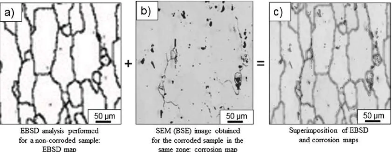
EB SD analyses were performed on three samples before H pre -charging and corrosion exposure using a JEOL JSM 7100F TTLS LV field-emission SEM and an OXFORD INIBUMENTS HKL EBSDsystem (Nordlys Nano EB SD detector - version 3.1 of the Aztec software). Samples were analysed at 20kV with a 12.5nA current. EBSD maps were performed on a 1. 5 mm X 3 mm area delimited by micro-hardness indents with a step size of 1.5 µmin the LT-ST plane. This selected area was large enough to obtain representative results. Overall, approxi -mately 1000 grains were analysed for each sample. The commercial orientation imaging software package Oxford Channel 5 was then used for the post-processing of the EBSD data. Prior to data analysis, in order to minimise measurement errors, ail grains comprising less than 9 pixels were automatically removed from the maps. Further, a lower limit boundary misorientation eut-off o f 3 • w as u sed t o eliminate spurious boundaries caused by orientation noise. The analyses allowed the determination of the nature of the interfaces (Fig. la) in relation with their level of misorientation in agreement with Priester who de -fines a grain boundary as the interface between two crystals, with the same crystallographic structure, with a greater or lesser degree of misorientation [ 40]. The word 'interfaces' refers, in this work, to the grain boundaries independent of their level of misorientation. Usually, a rotation angle of 15' was defined as the transition angle from LAGB, i.e. subgrain boundaries, and HAGB, i.e. grain boundaries. For pure aluminium, the critical angle for the transition LAGB /HAGB was be -tween 8.6' and 14.4' [41]. In this study, the critical misorientation angle to discriminate the subgrain boundaries and the grain boundaries was chosen to be equal to 10'. For grain boundaries, a distinction was made between coïncidence site lattice grain boundaries (CSL), where the degree of fit ( E) b etween the t wo structures of t be t wo grains is described by the reciprocal of the ratio of coïncidence sites to the total number of sites oriented, and random grain boundaries where the structure was observed as being disorganised. After the corrosion tests (24 h of immersion in 5 mM NaCl aerated solution), the selected area was analysed using SEM with the backscattered electron (BSE) detector to easily identify any IGC defects (Fig. lb).The corrosion map obtained was superimposed on the previous EB SD map of the non-corroded material (Fig. la) in order to determine the nature of the corroded in -terfaces (Fig. le). This procedure was performed for three corroded
b)
.,
t
-•
1
'
~
q
+
'
'
/ 1..
~~
t
non-<:harged samples and two corroded H-precharged samples; it per -mitted the determination of the misorientation level for each corroded interface (Fig. 1 c).
3. Results and discussion
3. I. Influence of Hon the IGC defect mo,phology
The morphology of the IGC defects was first investigated using OM after a 6 h exposure in a 5 mM NaCl aerated solution at room tem -perature (25 'C). Fig. 2a) and b) show OM micrographs of IGC defects formed on non-charged and H-precharged samples, respectively. For the non-charged sample (Fig. 2a), only a few IGC defects were detected (mean value = 6 defects/cm for a cross-section in the L-ST plane). Defects were thin and 86% of them were unbranched. For the H-pre-charged sample (Fig. 2b), IGC defects were more numerous (mean value= 28 defects/cm) and more branched: 26% of the IGC defects showed the morphology shown in Fig. 2b. The observations therefore highlighted an increase of the local reactivity, i.e. the anodic dissolution of the alloy, which was assumed to be related to the presence of H inside the sample. Further, IGC defects formed for a non-charged sample, after exposure to a more concentrated NaCl solution (1 M) and for longer duration (24 h) (insert in Fig. 2a) showed that IGC defects formed could become branched, but the level of ramifications observed was lower than for H-precharged samples. The evolution of the mor -phology of the IGC defects for the non-charged samples when the ex -posure to the NaCl solution was longer was assumed to be related to H diffusion all around the IGC defect, H being produced by the corrosion processes [25]. Therefore, the comparison of the IGC defect mor -phology for non-charged and H-precharged samples led us to assume a significant influence of H on the IGC defect propagation. Furthermore, the evolution of the IGC defect morphology with exposure time to NaCl solution seemed to confirm this hypothesis.
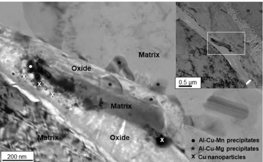
To go further in the characterisation of the IGC defects, conven -tional lift out procedure using a FEI HELIOS Nanolab 600i dual beam FIB / scanning electron microscope (SEM) was then used to obtain a thin sample in a specific region, i.e. near an IGC defect. Fig. 3 shows representative bright field (BF) TEM images showing a ramification of an IGC defect formed for an H-precharged sample of M 2024 T351 after a 24 h immersion in a 5 mM NaCl solution. A continuous pre -cipitation was observed along the two walls of the IGC defects in the upper ramification. The precipitates were identified as Al-Cu-Mn (71 % Al - 18% Cu -11 % Mn, at. %) and Al-Cu-Mg (83% Al - 15% Cu - 2% Mg, at. %) by EDX analyses. The morphology of Al-Cu-Mg precipitates suggested that they were partially dissolved. This was in agreement
..
. >
.
.
'
•
l, \~-..,
I
-,?,
~
~
,
..
\,.
·.\
\,
~m
EB SD analysis performed for a non-corroded sample:EBSD map
SEM (BSE) image obtained for the corroded sample in the
same zone: corrosion map
Superimposition ofEBSD and corrosion maps
Fig. 1. Methodology used to study the influence of H on the corrosion behaviour of AA 2024 alloy: a) EBSD map of the surface exposed (1.5 X 3 mm2) to the electrolyte before H precharging and corrosion tests; b) SEM image on BSE mode of the corroded surface (same zone) after immersion in a 5 mM NaCI solution during 24 h; c) EBSD map (Fig. la) superimposed to the corrosion map (Fig. lb).
with literature data, in particular the work of Birbilis et al. who studied at the nano-scale the dissolution of Al-Cu-Mg particles. The authors concluded that, even if many papers explained IGC considering mainly galvanic effects, their work suggested that the particles themselves dissolved and were the principle contributor to the localization of corrosion on this fine scale [42]. Considering Al-Cu-Mn precipitates, the work performed by Thompson et al. led to assume that the dissolution of the precipitates could not be excluded [21].Fig. 3also showed the formation of a Cu-rich layer at the matrix / IGC defect interface com-posed of Cu nanoparticles that should coincide with the first step of the Cu-rich layer formation as shown by Thompson et al. in their studies about anodisation of Al-Cu model alloys [43]. Overall, the morphology at the TEM scale of the IGC defects formed for the H-precharged sample was similar to that observed for a non-charged sample [20]. Therefore, the results suggested that H did not impact the IGC elementary me-chanisms. However, it probably modified the corrosion kinetics, by increasing the corrosion susceptibility of grain boundaries and subgrain boundaries. This was consistent with OM observations (Fig. 2) that showed the increase of the IGC defect density and their ramification for H-precharged samples. To provide experimental proof about this hy-pothesis, EBSD analyses were therefore performed on H-precharged samples by comparison to non-charged samples.
3.2. H influence on the susceptibility to corrosion of the interfaces depending on their level of misorientation
The distribution of the levels of misorientation of the interfaces for non-corroded AA 2024 alloy was studied for three samples: similar results were obtained with the three samples. Therefore, for more clarity,Fig. 4a represents the results for one sample only. In the selected zone (1.5 × 3 mm²), more than 1000 grains were present, which was a good indication of the number of analysed interfaces. Subgrain boundaries constituted the majority of interfaces, i.e. 59% of the stu-died interfaces, and only 41% were grain boundaries (Fig. 4a). The dark line inFig. 4a represents the distribution of the boundary misorienta-tions of a set of grains spread randomly and having a cubic symmetry [44]. Some similarities between the experimental grain boundaries distribution and the theoretical one were observed for θ > 10°, but the theoretical distribution did not completely fit with the experimental results. This could be explained considering the shaping treatment during the plate manufacturing. The presence of subgrains could be linked to the recovery process during the rolling. Moreover, in order to characterise the nature of the interfaces accurately, the distribution of the coincidence site lattice (CSL) grain boundaries was also studied (Fig. 4b). Results showed that 93% of the grain boundaries were random grain boundaries and only 7% were CSL grain boundaries, with Ʃ3 interfaces representing the majority of the CSL (14%) (Fig. 4b). Therefore, in the following, for the CSL grain boundaries, only the Ʃ3 grain boundaries were considered.
Fig. 2. Optical micrograph of IGC defects formed after a 6 h exposure at Ecorrin a 5 mM NaCl solution for a) non-charged and b) H-precharged samples of AA 2024 T351. Insert inFig. 2a shows an IGC defect after 24 h of immersion in a 1 M NaCl solution for a non-charged sample.
Fig. 3. Bright field (BF) TEM images showing a ramification of an IGC defect in H-precharged AA 2024 T351 after a 24 h immersion in a 5 mM NaCl solution.
a)
,,_
-Matrtx
•
Al-Cu-Mn
preclpltatea*
~-C
u-Mg
preclpltates X""cu-nanopartlclesThen, as explained in the experimental section (Fig. 1), the levels of misorientation of the corroded interfaces were recorded to establish a relationship between the level of misorientation of an interface and its susceptibility to corrosion. For this analysis, the duration of the corro-sion tests was 24 h in order to make enough IGC defects grow without introducing a too high H amount. For a non-charged sample, after the
corrosion test, 22 corroded interfaces were identified on the corroded area (4.5 mm²); all of them were analysed. Clearly, the number of in-terfaces analysed for the corroded non-charged sample was sig-nificantly lower than for the non-corroded sample, but the results were assumed to be representative considering that the same analysis was performed for three samples and similar results were obtained (Table 1).Fig. 5thus shows, as an example, the distribution of the levels of misorientation of these 22 corroded interfaces; in this figure, the distribution plotted for the non-corroded sample, with all the interfaces analysed in the selected zone of 4.5 mm2, is reported for comparison. Results showed that grain boundaries corresponded to 95% of the corroded interfaces whereas they represented only 41% of all the in-terfaces in the non-corroded material; further, their susceptibility to corrosion increased with their level of misorientation with a larger number of corroded interfaces identified for the highest levels of mis-orientation. In particular, it was calculated that 67% of the corroded interfaces had a misorientation angle higher than 40° whereas those interfaces constituted only half of the total interface population. Fi-nally, none of the 22 corroded interfaces observed were Ʃ3 CSL grain boundaries. The results were in perfect agreement with Guerin’s work performed for an AA 2050 alloy [18] and confirmed the strong re-activity of the grain boundaries with the highest levels of misorienta-tion, which may be linked to their disarranged structure and correlated with their high energy [44]. For the Ʃ3 CSL grain boundaries, Kim et al. also showed that these interfaces had a good resistance to IGC [16]. The
Fig. 4. AA 2024 T351: a) Distribution of the levels of misorientation of the
interfaces before H precharging and corrosion tests (non-corroded sample): the black curve represents the distribution of the boundaries misorientation of a set of grains spread randomly with a cubic symmetry [44] b) Distribution of the CSL grain boundaries before H precharging and corrosion tests.
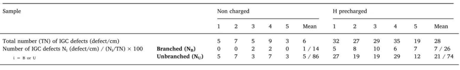
Table 1
Summary of the results obtained after the corrosion tests in a 5 mM NaCl solution. *For the corrosion tests in 3.1., results concerned IGC defects: when several corroded interfaces were connected together, they were considered as only one IGC defect. **For the corrosion tests in 3.2., each corroded interface was considered individually so that the concept of “ramification” (branched and unbranched) was not relevant in this part of the study. GB = grain boundaries and sGB = subgrain boundaries.
3.1. H / IGC defect morphology (6 h exposure in a 5 mM NaCl)*
Sample Non charged H precharged
1 2 3 4 5 Mean 1 2 3 4 5 Mean
Total number (TN) of IGC defects (defect/cm) 5 7 5 9 3 6 32 27 29 35 19 28
Number of IGC defects Ni(defect/cm) / (Ni/TN) × 100 i = B or U
Branched (NB) 0 0 2 2 0 1 / 14 5 8 10 6 7 7 / 26
Unbranched (NU) 5 7 3 7 3 5 / 86 27 19 19 29 12 21 / 74
3.2. H / susceptibility to corrosion of the interfaces (24 h exposure in a 5 mM NaCl)** Total number of corroded
interfaces (TNCI) Number (NC) of corroded GB or sGB / Percentage calculated considering the total number ofcorroded interfaces: (NC/TCNI) × 100 Random and special GB (except Ʃ3) Ʃ3 CSL GB sGB
Corroded non-charged samples
(4.5 mm²) 1 222 39 21 / 9538 / 97 0 / 00 / 0 1 / 51 / 3
3 18 18 / 100 0 / 0 0 / 0
Corroded H-precharged samples
(2.3 mm²) 1 3362 448 302 / 90399 / 89 10 / 313 / 3 24 / 736 / 8
Fig. 5. Distribution of the levels of misorientation of the corroded interfaces for
non-charged and H-precharged samples after a 24 h exposure at Ecorrin a 5 mM NaCl solution. The results obtained for the non-corroded alloy are reported for comparison (all interfaces present in the samples were analysed).
~ >-0 C QI ::, CT ~ IL 60~ - - -~ -50 10 14 12 10 B 6 4 59 % of subgraln boundaries 41 % of grain boundarles
[ill
0-5 5-10 10-15 15-20 20-25 25-30 30.35 35-40 40-45 45-50 50.55 55-60 60-65 Misorientation (0 ) M~~~~~~~~~;~~~~~~~~~~~~~~A~~~~~~~;;~~6~~~~~~~~!Special grain boundaries
r
so
~--~~---50~
40 ?i' c ~ 30 C".t
20 100
Non corroded~ Corroded / non charged
- Corroded / H precharged
0-5 5-10 10-15 15-20 20-25 25-30 30.35 35-40 40-45 45-50 50-55 55-60 6().65
boundaries are more susceptible to IGC than subgrain boundaries. However, in the presence of a large H amount, the subgrain boundaries susceptibility was increased and Ʃ3 CSL grain boundaries also became susceptible to corrosion.
3.3. New insight into the IGC mechanism for AA 2024
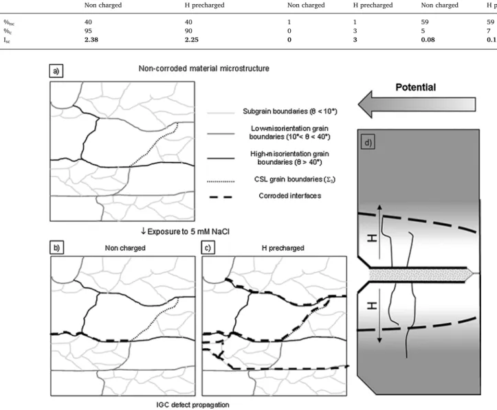
The results presented in the previous two paragraphs permitted to provide a new insight into the IGC mechanism for the AA 2024, high-lighting the influence of H produced during the corrosion processes. Fig. 6a is a schematic representation of the AA 2024 T351 micro-structure for a non-corroded sample. The most numerous interfaces are subgrain boundaries (59%).Fig. 6b shows the IGC initiation and pro-pagation of short IGC defects for a corroded non-charged sample. The IGC defects initiate following the common mechanism described in the literature [12], where intergranular Cu-rich particles promote the cor-rosion processes due to a galvanic coupling with the adjacent matrix. The intergranular precipitates are mostly present at the grain bound-aries, rather than at the subgrain boundbound-aries, because the high energy of the grain boundaries promotes the precipitation phenomenon. As a consequence, the corrosion processes mostly concern the grain bound-aries during the first time of exposure to the chloride media; therefore, the main part of the corroded interfaces are grain boundaries (Fig. 2a). However, the corrosion processes lead to the formation of a Cu-rich layer at the interface IGC defect/matrix, that promote the reduction of protons formed due to the cations hydrolysis. H diffused into the sample from the IGC defects where protons are produced as illustrated by SKPFM study [26], with the interfaces (both grain boundaries and subgrain boundaries) adjacent to the corroded interfaces acting as preferential diffusion paths. The H enrichment of those interfaces en-hances their electrochemical reactivity (Fig. 6d), promoting their dis-solution, as shown by AC-SECM measurements [28] so that IGC defects can progress laterally and become more and more branched when the duration of exposure to the chloride solution increased (insert in Fig. 2a). Further, Larignon et al. [26] showed a decrease of the corro-sion potential of AA 2024 in the presence of H; therefore, a galvanic coupling could occur between the H-enriched zone and the adjacent material where the H-enriched zone is the sacrificial anode. This could also explain the propagation of the IGC defects along the subgrain boundaries connected to the corroded grain boundaries. Overall, the H enrichment of the material during the corrosion processes provides an additional explanation to the evolution of the morphology of the IGC defects with increasing duration of exposure to the chloride solution. Clearly, when H was artificially inserted inside the material before the corrosion processes by cathodic charging, the corrosion processes were enhanced more rapidly as shown inFig. 6c with a stronger ramification of the IGC defects (Fig. 2b).
4. Conclusions
The present work was focused on the influence of H on the inter-granular corrosion (IGC) mechanisms of AA 2024 T351. The main re-sults can be summarised as follows:
1 At the optical and scanning electron microscopic scale, the IGC damage was found to be more extended with a significant ramifi-cation of the IGC defects for corroded H-precharged samples. At the transmission electron microscopic scale, no obvious difference was observed between corroded H-precharged and corroded non-charged samples; in both cases, the formation of a Cu-rich layer was observed at the matrix-oxide interface. It was therefore assumed that H did not influence the elementary processes of IGC, but it had a significant impact on the local reactivity.
2 EBSD analyses showed, for a corroded non-charged sample, that the most corroded interfaces were those with the highest levels of misorientation (grain boundaries, θ > 40°). Furthermore, the low energy of the subgrain boundaries provided also an explanation to
their higher resistance to corrosion [16,18,19,45,46].
Comparison of the results with those obtained for the H-precharged and corroded samples permitted to study the influence o f H o n the susceptibility to IGC of the AA 2024. In this case, results showed that the corrosion damage was significantly m ore e xtended i n agreement with OM observations (Fig. 2b). Therefore, the EBSD analyses was re-stricted to an area of 2.3 mm², i.e half-reduced area by comparison to the one studied for the corroded non-charged sample, in order to fa-cilitate the identification of the corroded interfaces. However, even for this reduced area, the number of IGC defects was equal to 336, all being analysed in this work (Fig. 5). As for the corroded non-charged samples, the experiments were repeated, in this case twice, and similar results were obtained (Table 1). Therefore, for more clarity, only the results obtained for the 336 corroded interfaces from the same H-precharged corroded sample are presented here. For the H-precharged corroded sample, a total of 93% of the corroded interfaces were grain boundaries and 7% of them were subgrain boundaries. Therefore, the results showed that H enhanced the susceptibility to IGC of the AA 2024 with an increase by a factor of fifteen of the number of corroded interfaces. Further, in the presence of H, the most susceptible interfaces to IGC remained the grain boundaries. However, the percentage of subgrain boundaries among the corroded interfaces increased from 5 to 7 for corroded non-charged and corroded H-precharged samples, respec-tively. Clearly, the increase could be considered as low; however, considering the significant number of corroded interfaces for the cor-roded H-precharged sample, the results clearly showed the significant enhancement of the corrosion susceptibility for subgrain boundaries: 24 corroded subgrain boundaries for a 2.3 mm² analysed area for the corroded H-precharged sample to be compared to only 1 corroded subgrain boundary for a 4.5 mm² analysed zone for the corroded non-charged sample. Furthermore, as indicated before and as shown in Table 1, the results were reproducible. They are also consistent with results obtained after 6 h of immersion in the NaCl solution (Fig. 2 and Table 1). H was thus found to enhance the susceptibility to corrosion of all the interfaces in such an extent that interfaces, which did not cor-rode when H amount was low, became susceptible to corrosion for a larger H amount. The corrosion behaviour of Ʃ3 CSL grain boundaries confirmed the results since, for the corroded H-precharged sample, 3% of the 336 corroded interfaces were Ʃ3 CSL grain boundaries whereas, for the corroded non-charged sample, no Ʃ3 CSL grain boundaries were corroded. To further quantify the results, the mean level of mis-orientation of each distribution was calculated. For the non-corroded sample, the mean level of misorientation was 39°, considering here all the interfaces in the selected zone. As explained before, for the corroded samples, the distributions were restricted to the corroded interfaces. For the corroded non-charged sample, a shift of the distribution was ob-served towards the high degrees of misorientation compared to the non-corroded sample. The mean level of misorientation was equal to 41.5°, which led us to assume that interfaces with a high level of mis-orientation were more susceptible to IGC. As indicated previously, the result was obtained for a low number of corroded interfaces, but it was confirmed by the analysis of two other samples and was in agreement with literature data [17,18]. By comparison, the distribution of the corroded grain boundaries for the corroded H-precharged sample was more similar to that of the non-corroded alloy, with subgrain bound-aries, but also grain boundaries with a low level of misorientation (10° < θ < 40°) that became more reactive leading to a decrease of the mean value of the level of misorientation to 37.5°. In that case, the result was obtained for a large number of corroded interfaces. As done by Guerin et al. [18], an IGC susceptibility index (ISC) was also calcu-lated for the different types of interfaces (subgrain boundaries, random and Ʃ3 CSL grain boundaries). It was determined by the ratio of the proportion of corroded interfaces (%c) divided by the proportion of the interfaces of the same type identified f or t he n on-corroded sample (%nc).The results are summarised in Table 2 and confirmed that grain
presence of H strongly increased the number of corroded interfaces and made subgrain boundaries (θ < 10°), grain boundaries with low misorientation angle (10° < θ < 40°) and Ʃ3 CSL grain boundaries susceptible to IGC.
3 The results were analysed considering previous work that showed that H could both lower the corrosion potential of AA 2024 and increase its reactivity probably due to the disturbance of the crys-tallographic lattice. They allowed to propose a new insight into the IGC mechanism for AA 2024 where the corrosion-induced H that was trapped inside the IGC defects could then modify the local re-activity of the material. The embrittlement of new interfaces, in which H had diffused, was assumed to explain the ramification of the IGC defects when the duration of exposure to the chloride so-lution was increased.
In this study, corrosion tests were performed under isothermal conditions and results are thus immediately applicable for structural components used in these conditions. However, when dealing with aerospace industry and real flying conditions, some structural parts can
experience thermal cycles with exposure to temperatures < 0 °C. In those conditions, the solidification of the electrolyte trapped inside the IGC defect can generate stress concentration at the IGC defect tip, which should lead to larger H enrichment of the corroded alloy. Therefore, the H-enhanced corrosion mechanism proposed in this study might be helpful in predicting the lifetime of those structural compo-nents.
Data availability
The raw/processed data required to reproduce these findings cannot be shared at this time as the data also forms part of an ongoing study.
Acknowledgement
This work was supported by ANR-14-CE07-0027-01 (France) – M-SCOT: Multi Scale COrrosion Testing.
Table 2
Calculation of the IGC susceptibility index (ISC) for the different types of interfaces for AA 2024 samples exposed to a 5 mM NaCl solution for 24 h. Non-charged and H-precharged samples are corroded samples here.
Type of interfaces Random and special (except Ʃ3) grain boundaries Ʃ3 CSL grain boundaries Subgrain boundaries
Non charged H precharged Non charged H precharged Non charged H precharged
%nc 40 40 1 1 59 59
%c 95 90 0 3 5 7
Isc 2.38 2.25 0 3 0.08 0.12
Fig. 6. IGC Mechanism for AA 2024 T351. a) Microstructure of the non-corroded material with identification of the interfaces. Identification of the corroded
interfaces for b) non-charged and c) H-precharged samples after immersion in a NaCl solution. d) Scheme of the H influence on the local reactivity. Non-corroded material microstructure
,l. Exposureto 5 mM NaCI
Non charged
0
Subgrain boundaries (8 < 10")
Lowmisorientation grain
boundaries (10"< 8 < 40")
High-m isorientation grain boundaries (8 > 40") CSL grain boundaries(t,) Corroded interfaces H precna rged
,---r---,
~ _:..
····
·
·
·
'
.
.
·
··"
..
.
.
•··
.
..
IGC defect propagation
Potent
l
al
<.---'
---[1] Commission on Engineering and Technical Systems, Aging of U.S. Air Force Aircraft: Final Report, National Academies Press, Washington, 1997 ISBN 0309174473, 9780309174473.
[2] Success stories: air force; material substitution and new sealing, 4, s.l. AMPTIAC Q. 7 (2003).
[3] Z. Wang, P. Chen, H. Li, B. Fang, Z. Zheng, The intergranular corrosion suscept-ibility of 2024 Al alloy during re–ageing after solution treating and cold–rolling, Corros. Sci. 114 (2017) 156–168.
[4] R. Bonzom, R. Oltra, Intergranular corrosion propagation rate of 2024 alloy in-vestigated via the “one-dimensional artificial pit” technique, Corros. Sci. 111 (2016) 850–855.
[5] S.P. Knight, M. Salagaras, A.M. Wythe, F. De Carlo, A.R. Trueman, In situ X-ray tomography of intergranular corrosion of 2024 and 7050 aluminium alloys, Corros. Sci. 52 (2010) 3855–3860.
[6] J.A. DeRose, T. Suter, A. Bałkowiec, J. Michalski, K.J. Kurzydlowski, P. Schmutz, Localised corrosion initiation and microstructural characterisation of an Al 2024 alloy with a higher Cu to Mg ratio, Corros. Sci. 55 (2012) 313–325.
[7] T. Hu, H. Shi, D. Hou, T. Wei, S. Fan, F. Liu, E.-H. Han, A localized approach to study corrosion inhibition of intermetallic phases of AA 2024-T3 by cerium malate, Appl. Surf. Sci. 467–468 (2019) 1011–1032.
[8] B.G. Prakashaiah, D. Vinaya Kumara, A. Anup Pandith, A. Nityananda Shetty, B.E. Amitha Rani, Corrosion inhibition of 2024-T3 aluminum alloy in 3.5% NaCl by thiosemicarbazone derivatives, Corros. Sci. 136 (2018) 326–338.
[9] W. Zhang, G.S. Frankel, Transitions between pitting and intergranular corrosion in AA2024, Electrochim. Acta 48 (2003) 1193–1210.
[10] J. Wloka, S. Virtanen, Detection of nanoscale η-MgZn2phase dissolution from an
Al-Zn-Mg-Cu alloy by electrochemical mocrotransients, Surf. Interface Anal. 40 (2008) 1219–1225.
[11] V. Guillaumin, G. Mankowski, Localised corrosion of 2024 T351 aluminum alloy in chloride media, Corros. Sci. 41 (1998) 421–438.
[12] J.R. Galvele, S.M. DeMicheli, Mechanism of intergranular corrosion of Al-Cu alloys, Corros. Sci. 10 (1970) 795–807.
[13] V.Y. Gertsmann, S.M. Bruemmer, Study of grain boundary character along inter-granular stress corrosion crack paths in austenitic alloys, Acta Mater. 49 (2001) 1589–1598.
[14] V. Randle, The coincidence site lattice and the ‘sigma enigma’, Mater. Charact. 47 (2001) 411–416.
[15] X.Y. Fang, W.G. Wang, H. Guo, X. Zhang, B.X. Zhou, Corrosion behaviors of random and special grain boundaries in a sensitized 304 stainless steel, J. Iron Steel Res. Intern. 14 (2007) 339–343.
[16] S.H. Kim, U. Erb, K.T. Aust, Grain boundary character distribution and inter-granular corrosion behavior in high purity aluminum, Scripta Mater. 44 (2001) 835–839.
[17] A.J. Davenport, Y. Yuan, R. Ambat, B.J. Connolly, M. Strangwood, A. Afseth, G.M. Scamans, Intergranular corrosion and stress corrosion cracking of sensitised AA5182, Mater. Sci. Forum. 519–521 (2006) 641–646.
[18] M. Guérin, J. Alexis, E. Andrieu, L. Laffont, W. Lefebvre, G. Odemer, C. Blanc, Identification of the metallurgical parameters explaining the corrosion suscept-ibility in a 2050 aluminium alloy, Corros. Sci. 102 (2016) 291–300.
[19] C. Luo, X. Zhou, G.E. Thompson, A.E. Hugues, Observations of intergranular cor-rosion in AA2024-T351: the influence of grain stored energy, Corros. Sci. 61 (2012) 35–44.
[20] M.L. de Bonfils-Lahovary, L. Laffont, C. Blanc, Characterization of intergranular corrosion defects in a 2024 T351aluminium alloy, Corros. Sci. 119 (2017) 60–67. [21] Y. Ma, X. Zhou, G.E. Thompson, M. Curioni, X. Zhong, E. Koroleva, P. Skeldon,
P. Thomson, M. Fowles, Discontinuities in the porous anodic film formed on AA2099-T8 aluminium alloy, Corros. Sci. 53 (2011) 4141–4151.
[22] T. Hashimoto, X. Zhou, P. Skeldon, G.E. Thompson, Structure of the copper-en-riched layer introduced by anodic oxidation of copper-containing aluminium alloy, Electrochim. Acta 179 (2015) 394–401.
[23] X. Zhou, C. Luo, Y. Ma, T. Hashimoto, G.E. Thompson, A.E. Hugues, P. Skeldon, Grain stored energy and the propagation of intergranular corrosion in AA2xxx
[24] T. Hashimoto, X. Zhang, X. Zhou, P. Skeldon, S.J. Haigh, G.E. Thompson, Investigation of dealloying of S phase (Al2CuMg) in AA 2024-T3 aluminium alloy
using high resolution 2D and 3D electron imaging, Corros. Sci. 103 (2016) 157–164.
[25] M.L. de Bonfils-Lahovary, M.C. Lafouresse, J. Delfosse, L. Laffont, C. Blanc, Characterization and control of the intergranular corrosion defects in a 2024 T351 aluminium alloy, Proceeding CORROSION 2017, NACE Conference Paper, (2017) RIP 2017-9427.
[26] C. Larignon, J. Alexis, E. Andrieu, L. Lacroix, G. Odemer, C. Blanc, Investigation of Kelvin probe force microscopy efficiency for the detection of hydrogen ingress by cathodic charging in an aluminium alloy, Scripta Mater. 68 (2013) 479–482. [27] M.C. Lafouresse, M.L. de Bonfils-Lahovary, C. Charvillat, L. Oger, L. Laffont,
C. Blanc, A Kelvin probe force microscopy study of hydrogen insertion and deso-rption into 2024 aluminum alloy, J. Alloys Comp. 722 (2017) 760–766. [28] M.C. Lafouresse, M.L. de Bonfils-Lahovary, L. Laffont, C. Blanc, Hydrogen mapping
in an aluminium alloy using an alternating current scanning electrochemical mi-croscope (AC-SECM), Electrochem. Commun. 80 (2017) 29–32.
[29] R.F. Schaller, S. Thomas, N. Birbilis, J.R. Scully, Spatially resolved mapping of the relative concentration of dissolved hydrogen using the scanning electrochemical microscope, Electrochem. Commun. 51 (2015) 54–58.
[30] S. Thomas, N. Ott, R.F. Schaller, J.A. Yuwono, P. Volovitch, G. Sundararajan, N.V. Medhekar, K. Ogle, J.R. Scully, N. Birbilis, The effect of absorbed hydrogen on the dissolution of steel, Heliyon 2 (2016) e00209.
[31] W. Barrows, R. Dingreville, D. Spearot, Traction-separation relationships for hy-drogen induced grain boundary embrittlement in nickel via molecular dynamics simulations, Mater. Sci. Eng. A650 (2016) 354–364.
[32] Y. Takahashi, H. Kondo, R. Asano, S. Arai, K. Higuchi, Y. Yamamoto, S. Muto, N. Tanaka, Direct evaluation of grain boundary hydrogen embrittlement: a micro-mechanical approach, Mater. Sci. Eng. A 661 (2016) 211–216.
[33] A. Oudriss, J. Bouhattate, C. Savall, J. Creus, X. Feaugas, F.A. Martin,
P. Laghoutaris, J. Chêne, On the implication of hydrogen on inter-granular fracture, Procedia Mater. Sci. 3 (2014) 2030–2034.
[34] A. Oudriss, J. Creus, J. Bouhattate, C. Conforto, C. Berziou, C. Savall, X. Feaugas, Grain size and grain boundary effects on diffusion and trapping of hydrogen in pure nickel, Acta Mater. 19 (2012) 6814–6829.
[35] A. Oudriss, S. Le Guernic, Z. Wang, B. Osman Hoch, J. Bouhattate, E. Conforto, Z. Zhu, D.S. Li, X. Feaugas, Meso-scale anisotropic hydrogen segregation near grain-boundaries in polycrystalline nickel characterized by EBSD/SIMS, Mater. Lett. 165 (2016) 217–222.
[36] S. Bechtle, M. Kumar, B.P. Somerday, M.E. Launey, R.O. Ritchie, Grain-boundary engineering markedly reduces susceptibility to intergranular hydrogen embrittle-ment in metallic materials, Acta Mater. 57 (2009) 4148–4157.
[37] H.K. Birnbaum, C.E. Buckley, F. Zeides, E. Sirois, P. Rozenak, S. Spooner, J.S. Lin, Hydrogen in aluminium, J. Alloys Comp. 253 (1997) 260–264.
[38] W. Zhang, G.S. Frankel, Localized corrosion growth kinetics in AA2024 alloys, J. Electrochem. Soc. 149 (2002) B510–B519.
[39] W. Zhang, G.S. Frankel, Anisotropy of localized corrosion in AA2024-T3, Electrochem. Sol. State Lett. 3 (2000) 268–270.
[40] L. Priester, Les joints de grains: De la théorie à l’ingénierie, s.l. EDP Sci. (2006). [41] M. Winning, A.D. Rollet, Transition between low and high angle grain boundaries,
Acta Mater. 53 (2005) 2901–2907.
[42] N. Birbilis, M.K. Cavanaugh, L. Kovarik, R.G. Buchheit, Nano-scale dissolution phenomena in Al–Cu–Mg alloys, Electrochem. Com. 10 (2008) 32–37. [43] S. Garcia-Vergara, P. Skeldon, G.E. Thompson, P. Bailey, T.C.Q. Noakes,
H. Habazaki, K. Shimizu, Morphology of enriched alloy layers in an anodized Al-Cu alloy, Appl. Surf. Sci. 205 (2003) 121–127.
[44] F.J. Humphreys, M. Hatherly, Recrystallization and Related Annealing Phenomena, second edition, Elsevier, 2004 s.l..
[45] B.W. Bennett, H.W. Pickering, Effect of grain boundary structure on sensitization and corrosion of stainless steel, Metal. Trans. A 18A (1987) 1117–1124. [46] S.R. Ortner, V. Randle, A study of the relation between grain boundary type and
sensitisation in a partially-sensitised AISI 304 stainless steel using electron back-scattering patterns, Scr. Metall. Mater. 23 (1989) 1903–1908.