UNIVERSITÉ DE MONTRÉAL
MINING WASTEWATER TREATMENT BY SLAG FILTERS
DOMINIQUE CLAVEAU-MALLET
DÉPARTEMENT DES GÉNIES CIVIL, GÉOLOGIQUE ET DES MINES ÉCOLE POLYTECHNIQUE DE MONTRÉAL
MÉMOIRE PRÉSENTÉ EN VUE DE L’OBTENTION DU DIPLÔME DE MAÎTRISE ÈS SCIENCES APPLIQUÉES
(GÉNIE CIVIL) JUIN 2012
UNIVERSITÉ DE MONTRÉAL
ÉCOLE POLYTECHNIQUE DE MONTRÉAL
Ce mémoire intitulé:
MINING WASTEWATER TREATMENT BY SLAG FILTERS
présenté par : CLAVEAU-MALLET Dominique
en vue de l’obtention du diplôme de : Maîtrise ès sciences appliquées a été dûment accepté par le jury d’examen constitué de :
M. COURCELLES Benoît, Ph. D., président
M. COMEAU Yves, Ph. D., membre et directeur de recherche M. WALLACE Scott, Ph. D., membre et codirecteur de recherche Mme POTVIN Estelle, Ph. D., membre
ACKNOWLEDGEMENTS
Thank you to my director Yves Comeau for his trust in me and his constant presence.
Thank you to laboratory technicians who helped me in this project: Denis Bouchard for technical support and phosphorus analysis, Manon Leduc for metals analysis, Marie Ferland for fluoride analysis and preparation of feeding solutions, Yvéric Rousseau for the preparation of figures 4.2, 4.4 and 4.7 and Jean-Philippe Massé for the X-ray diffraction analysis support and for transmission electronic microscopy analysis.
Thank you to my codirector Scott Wallace, from Naturally Wallace Consulting, for his presence all along the project and for his precious advices. Thank you to professionals from Shaw Environmental, who realized the preliminary feasibility study related to this project, especially to Ernie Stine, who provided a preliminary list of slag suppliers. Thank you to all slag suppliers who sent samples. Thank you to Judy Lissick, from Naturally Wallace Consulting, for her technical support in the slag samples shipment.
Thank you to Aurore Bordier, intern at École Polytechnique during the summer and fall 2011, who sampled and took care of my experiments during my maternity leave.
A special thank you to professor Kalle Kirsimäe, to Riho Mõtlep and Martin Liira, from the Department of Geology from the University of Tartu, Estonia, for the oxide composition analysis of slag.
Thank you to the Natural Sciences and Engineering Research Council of Canada, to the Fonds québécois de recherche sur la nature et les technologies, to Naturally Wallace Consulting, to the Société de recherche en aquaculture continentale, to the Réseau aquaculture Québec, to Arcelor Mittal and to Harsco Materials for the funding of this project.
Thank you to Mathieu Bélisle for the exceptional support that enabled me to realize this project, and to my baby Rosanne who was nice when I was writing my master thesis.
RÉSUMÉ
Les deux objectifs de ce projet étaient de proposer un système de traitement par filtres à scories du lixiviat de la mine Joplin, Missouri et de proposer un modèle préliminaire des mécanismes de rétention du phosphore dans les filtres à scories. Trois phases expérimentales ont été réalisées : essais individuels en flacon, essais séquentiels en flacon et essais en colonnes. Les essais individuels en flacon ont été utilisés pour comparer la performance de traitement de 10 scories et 1 apatite et pour choisir les meilleurs matériaux parmi ceux-ci. Les essais séquentiels en flacon ont été utilisés pour comparer les performances de traitement de quelques séquences de filtres. Finalement, les essais en colonnes ont été utilisés pour caractériser la performance d’enlèvement et la longévité d’un filtre soumis à des conditions d’alimentation contrôlées. Durant les essais en colonnes, l’effet de la composition de l’affluent, du temps de rétention hydraulique des vides et de la séquence de filtre a été mesuré. Certains essais en colonnes ont été opérés spécifiquement pour étudier les mécanismes d’enlèvement du phosphore.
Le modèle proposé est défini par les étapes suivantes : 1) la dissolution cinétique des scories est représentée par la dissolution de CaO, 2) un fort pH dans le filtre cause la précipitation du phosphore et la croissance de cristaux, 3) la rétention des cristaux est causée par filtration, décantation et densification, 4) la diminution du volume de réaction (et du temps de réaction) disponible est causée par l’accumulation de cristaux et autres particules dans les vides, 5) le pH dans le filtre diminue avec le temps si le temps de réaction est trop court (ce qui résulte en une diminution de l’efficacité d’enlèvement). Une nouvelle approche pour définir les performances des filtres à scories est proposée. La capacité de rétention à saturation est exprimée en mg P / mL de vides.
Le système proposé pour traiter le lixiviat de la mine Joplin est composé de deux filtres successifs de scories EAF Fort Smith opérés à un temps de rétention hydraulique des vides total de 34 h. Après 179 jours d’opération, les performances de traitement des deux filtres ont été de 99.9 %, 85.3 %, 98.0 % et 99.3 % pour le phosphore, le fluor, le manganèse et le zinc, respectivement.
ABSTRACT
The two objectives of this project were to propose a slag filters treatment system for the leachate of the Joplin mine, Missouri, and propose a preliminary model for phosphorus removal mechanisms in slag filters. Three experimental phases were realized: individual batch tests, sequential batch tests and column tests. Individual batch tests were used to compare the treatment performance of 10 slags and 1 apatite and to select the best materials from this list. Sequential batch tests were used to compare the treatment performance of several filter sequences. Finally, column tests were used to characterize the removal performance and longevity of controlled filters. During column tests, the effect of influent composition, void hydraulic retention time and filter sequences was measured. Some column tests were operated especially for the study of phosphorus removal mechanisms.
The proposed model is expressed by the following steps: 1) the rate limiting dissolution of slag is represented by the dissolution of CaO, 2) a high pH in the slag filter results in phosphorus precipitation and crystal growth, 3) crystal retention takes place by filtration, settling and growth densification, 4) the decrease in available reaction volume is caused by crystal and other particulate matter accumulation (and an associated decrease in available reaction time), and 5) the pH decreases in the filter over time if the reaction time is too short (which results in a reduced removal efficiency). A new approach to define filter performance is proposed. Saturation retention capacity is expressed in units of mg P/ mL voids.
The proposed system for the treatment of the Joplin mine leachate is composed of two successive Fort Smith EAF slag filters operated at a total void hydraulic retention time of 34 hours. After 179 days of operation, the treatment performance of this system was 99.9 %, 85.3 %, 98.0 % et 99.3 % for phosphorus, fluoride, manganese and zinc respectively.
CONDENSÉ EN FRANÇAIS
Les sites miniers abandonnés ont des impacts significatifs sur l’environnement. La dégradation des paysages s’ajoute à la pollution directe des cours d’eau avoisinants par les lixiviats miniers. Dans ce projet, on s’intéresse à une mine de gypse abandonnée située à Joplin, au Missouri. De fortes concentrations de plusieurs contaminants (phosphore, fluor et métaux) étaient présentes dans le cours d’eau récepteur. Ce site a été restauré par la mise en place d’une station d’épuration chimique, qui est toujours en opération. Le lixiviat minier est collecté et traité à la chaux pour précipiter les contaminants. Cependant, ce système ne répond plus aux exigences de rejet les plus récentes. Le Gouvernement du Missouri a décidé d’investir dans une nouvelle technologie de traitement qui serait économique et plus efficace que le système actuel. Dans une analyse préliminaire, les filtres à scories d’aciérie, qui sont un résidu de production de l’industrie de l’acier, ont été choisis pour répondre à ce défi. L’École Polytechnique a été mandatée via ce projet de maîtrise pour mettre en œuvre la première partie du projet de mise à niveau.
Objectif 1 : Proposer, à partir d’essais en laboratoire, un filtre à scories pour le traitement du lixiviat minier Joplin. Le système proposé doit être économique et répondre aux nouvelles exigences de rejet.
Une deuxième problématique a été abordée. Le traitement du phosphore par les filtres à scories est bien connu, mais les performances sont variables d’une étude à l’autre. À ce jour, il n’existe pas d’outils de prédiction de performance pour les filtres à scories. Une compréhension globale et une conceptualisation des phénomènes impliqués dans les filtres à scories sont nécessaires pour développer de tels outils de prédiction.
Objectif 2 : Proposer un modèle préliminaire des mécanismes d’enlèvement du phosphore dans les filtres à scories.
Le programme expérimental a comporté trois phases : les essais individuels en flacon, les essais séquentiels en flacon et les essais en colonnes. Trois eaux minières synthétiques, représentant les concentrations minimales, moyennes et maximales retrouvées sur le site, ont été reconstituées au laboratoire à partir de sels chimiques. Dix types de scories (neuf en provenance des États-Unis et une en provenance du Québec) et un type d’apatite (en provenance de la Floride) ont été testés.
Les essais individuels en flacon sont des essais comparatifs utilisés pour dresser une liste de scories par potentiel de traitement. 35 g de scories ont été mis en contact dans 700 mL d’eau usée, puis mis en rotation à 170 rpm et 20°C pour une durée de 2 jours. La concentration résiduelle des contaminants a été mesurée après 24 h et 48 h. Les essais ont été réalisés en duplicatas dans deux types d’eau (concentration minimale et concentration maximale).
Un essai séquentiel en flacon est une version modifiée de l’essai individuel. Après 24 h de réaction avec un premier type de scorie, la solution est filtrée à 0,45 microns puis mise en contact avec 35 g d’un deuxième type de scorie pour 24 h supplémentaires. La concentration des contaminants est mesurée après chaque tranche de 24 h. Les résultats des séquences sont ensuite comparés avec ceux des essais individuels. Seules les scories sélectionnées à partir de l’étape précédente sont testées en duplicata. Les essais sont réalisés dans un seul type d’eau (concentration maximale).
La configuration des essais en colonnes est déterminée sur la base des résultats des deux étapes précédentes. Neuf essais sont réalisés avec des paramètres variables (séquence de filtres, type de scorie et débit d’alimentation). Trois types de scories sont testés (les scories EAF de Blytheville, EAF de Contrecoeur et EAF de Fort Smith). Différents temps de rétention hydraulique sont testés (1.5 h à 19 h). Les séquences testées sont : scories Contrecoeur seules, scories Fort Smith seules, scories Blytheville seules et scories Fort Smith suivies de scories Blytheville. Les colonnes étaient faites de plastique PVC transparent et avaient une longueur de 17 cm et un diamètre de 15 cm. L’effluent des colonnes a été échantillonné deux fois par semaine pour le suivi des paramètres (pH, Ca, P, Mn, Zn, Al, F). Les essais en colonnes ont duré de 30 à 630 jours, la plupart d’entre eux ayant duré de 150 à 200 jours. Les précipités formés dans les colonnes ont été échantillonnés à la fin des essais et caractérisés par diffraction aux rayons X (détermination de la composition et de la taille) et par microscope électronique à transmission (étude de la forme et de l’organisation des précipités). Des essais de toxicité ont été réalisés sur les scories utilisées dans les essais en colonnes.
Les résultats des essais individuels en flacon ont indiqué que trois scories se sont démarquées pour leur capacité à monter le pH et à traiter le phosphore (scories BOF d’Indiana Harbor East, scories EAF de Fort Smith, scories BOF de Cleveland). Les scories EAF de Blytheville ont été les plus efficaces pour traiter le fluor, mais leur efficacité a diminué lorsque
l’eau à traiter était trop concentrée (faible capacité à monter le pH des scories). Cette observation a déterminé le choix des séquences à tester lors des essais séquentiels en flacon. Peut-on augmenter la capacité de traitement du fluor des scories EAF Blytheville par un filtre préliminaire de scories à forte capacité de hausse du pH?
Les résultats des essais séquentiels en flacon ont indiqué que la séquence Fort Smith – Blytheville a permis d’augmenter la capacité de traitement globale de la chaîne de traitement. On a observé d’abord une forte montée du pH, ensuite un bon traitement de tous les contaminants, en particulier le fluor. Les scories EAF de Fort Smith et EAF de Blytheville ont été sélectionnées pour les essais en colonnes. Les scories BOF Cleveland étaient trop friables et les scories BOF d’Indiana Harbor East étaient moins efficaces que les scories EAF de Fort Smith. Les scories EAF de Contrecoeur ont été testées en colonnes pour étudier les mécanismes d’enlèvement du phosphore parce que leur comportement avait été bien caractérisé lors d’études antérieures à Polytechnique. Les essais de toxicité réalisés sur ces trois scories ont montré qu’elles étaient sécuritaires pour l’environnement parce que leur relargage dans l’eau distillée résultait en des concentrations en dessous des seuils de performance cibles pour une variété de contaminants (cuivre, fer, plomb, nickel, zinc).
Un modèle préliminaire des mécanismes d’enlèvement du phosphore a été proposé. Il est défini par les étapes suivantes : 1) la dissolution cinétique des scories est représentée par la dissolution de CaO, 2) un fort pH dans le filtre cause la précipitation du phosphore et la croissance de cristaux, 3) la rétention des cristaux est causée par filtration, décantation et densification, 4) la diminution du volume de réaction (et du temps de réaction) disponible est causée par l’accumulation de cristaux et autres particules dans les vides, 5) le pH dans le filtre diminue avec le temps si le temps de réaction est trop court (ce qui résulte en une diminution de l’efficacité d’enlèvement). L’organisation des cristaux dans un filtre à scories détermine sa capacité de rétention du phosphore. Une organisation compacte des cristaux augmente la capacité de rétention du filtre. Une nouvelle approche pour définir les performances des filtres à scories est proposée. La capacité de rétention à saturation est exprimée en mg P / mL de vides.
Les résultats des essais en colonnes applicables à la mine Joplin ont indiqué que la meilleure performance de traitement a été obtenue par deux filtres successifs composés de scories EAF Blytheville. Ce système a atteint des abattements de 98.8 %, 94.8 %, 94.4 % et 98.6 % pour
le phosphore, le fluor, le manganèse et le zinc, respectivement, après 169 jours d’opération. Cependant, l’efficacité du premier filtre a diminué après 30 jours d’opération, limitant son utilisation à long terme. Le système composé de deux filtres successifs Fort Smith a été moins efficace pour le traitement du fluor, mais la capacité maximale de traitement du premier filtre a été conservée durant 70 jours. Après 179 jours d’opération, les performances de traitement des deux filtres ont été de 99.9 %, 85.3 %, 98.0 % et 99.3 % pour le phosphore, le fluor, le manganèse et le zinc respectivement. Ainsi, le système recommandé est composé de deux filtres successifs de scories EAF Fort Smith opérés à un temps de rétention hydraulique des vides total de 34 h.
Un fort lien entre le pH de l’effluent et la concentration en phosphore a été observé. La composition de l’eau usée a eu une influence sur l’enlèvement du fluor. L’abattement moyen à pleine capacité a été de 10% en eau faiblement concentrée et de 85% en eau fortement concentrée dans les filtres Fort Smith. L’enlèvement du fluor est augmenté lorsque le ratio fluor/phosphore est bas, favorisant la précipitation de fluoroapatite. L’efficacité d’enlèvement des métaux était liée au pH de façon semblable au phosphore. L’abattement moyen à pleine capacité des scories Blytheville et Fort Smith était de 75% pour le manganèse et supérieur à 90% pour le zinc. Le manganèse n’était pas traité si le pH était plus bas que 6.
La comparaison des résultats avec les exigences de rejets a indiqué que le système retenu ne répond pas à la cible de rejet visée en phosphore total. En effet, la concentration de phosphore à l’effluent du système en pleine capacité se situe en moyenne entre 0.01 et 0.1 mg P/L alors que la cible était de 0.0005 mg P/L. Cependant, l’efficacité de traitement des filtres à scories est comparable à celle de technologies complexes et coûteuses, par exemple les membranes. Considérant la simplicité économique des filtres à scories, leur performance d’enlèvement du phosphore pourrait être acceptée. La cible de performance du fluor n’a pas été atteinte. L’exigence de rejet était de 2 μg/L tandis que la concentration à l’effluent des filtres se situait entre 2 et 7 mg/L. Cependant, de telles concentrations sont très basses si on les compare à des effluents traités d’autres types d’eaux usées contenant du fluor. Elles sont du même ordre de grandeur que la recommandation du Canada pour le fluor dans l’eau potable. De plus, l’enlèvement du fluor était considéré comme un objectif secondaire, la priorité étant le traitement du phosphore. Considérant les circonstances précédentes, les performances de traitement du fluor des filtres à scories semblent acceptables puisque 99,9% du phosphore et 85,3% du fluor ont été
abattu, respectivement. Les exigences de rejet pour l’enlèvement des métaux étudiés ont été atteintes. La concentration à l’effluent du système proposé était de 0,2 à 1 mg/L d’aluminium et de 0,01 à 0,03 mg/L de zinc. Les exigences de rejet étaient de 187 mg/L pour l’aluminium et de 0,042 mg/L pour le zinc.
La croissance de cristaux dans les filtres a été étudiée avec la détermination de la taille des cristaux. Une interprétation qualitative des taux de croissance d’apatite dans les filtres amont a indiqué que ceux-ci sont dépendants de la composition de l’eau usée. Plus la concentration en phosphore est élevée, plus le taux de croissance est rapide. Les courbes taille de cristaux – temps se développaient en forme d’éventail. Cette observation suggère que de nouveaux cristaux sont continuellement formés pendant que les cristaux déjà en place continuent de croître, résultant en une distribution de tailles de cristaux, les noyaux les plus vieux étant les plus gros. La composition d’hydroxyapatite des cristaux a été observée très tôt. L’hydroxyapatite était la principale phase minéralogique après 30 jours. Ainsi, les phosphates de calcium précurseurs à l’hydroxyapatite, qui sont soit des solides amorphes ou des phases minéralogiques instables, ont été assez rapidement transformés en hydroxyapatite.
La formation de calcite a été observée dans les filtres alimentés avec de l’eau usée contenant du carbone inorganique. La formation de calcite est compétitive à la formation d’hydroxyapatite. Les cristaux de calcite étaient systématiquement plus gros que les cristaux d’hydroxyapatite. La calcite occupe de l’espace qui n’est plus disponible pour la formation et la croissance d’hydroxyapatite. L’augmentation du temps de rétention hydraulique des vides a favorisé la précipitation de calcite, ce qui souligne l’importance de l’optimisation du temps de rétention hydraulique. Un long temps de rétention hydraulique favorise la précipitation compacte et augmente la capacité de rétention de cristaux, mais la proportion de calcite dans les cristaux est plus grande. La présence de calcite dans les interstices est également favorisée par le contact direct du filtre avec l’atmosphère.
L’utilisation de filtres à scories EAF Fort Smith est recommandée pour le traitement du lixiviat minier à Joplin. Les résultats de cette étude indiquent que deux filtres successifs Fort Smith ayant un temps de rétention hydraulique total de 34 heures ont été très efficaces durant au moins 172 jours. La longévité du système peut être augmentée en ajoutant des filtres successifs. L’utilisation des scories EAF Blytheville n’est pas recommandée parce que sa longévité est trop
courte, même si sa capacité de traitement du fluor est plus grande que celle des scories Fort Smith. En prévision de futurs essais en colonnes et pilote à la mine, certaines recommandations additionnelles ont été formulées : l’utilisation d’un lixiviat minier réel, la réalisation d’essais en colonnes en réplicata, l’utilisation de scories provenant de différentes piles de production, le suivi de tous les métaux incluant les métaux lourds, l’utilisation de mélanges de scories Fort Smith avec une petite quantité de scories Blytheville et l’optimisation du temps de rétention hydraulique et de la longévité par rapport aux coûts d’installation et de remplacement.
Des recommandations pour améliorer le modèle des mécanismes d’enlèvement du phosphore dans les filtres à scories ont été formulées. La caractérisation précise de la cinétique de dissolution des scories est nécessaire, tout comme une étude approfondie des caractéristiques des cristaux, incluant leur forme, leur organisation, ainsi que les phénomènes de nucléation et croissance. Le modèle doit être complété par des notions de perméabilité et de diffusion dans les médias granulaires. Tous les phénomènes impliqués dans les filtres à scories doivent être réunis dans un modèle numérique qui permette de prédire les performances des filtres.
TABLE OF CONTENTS
AKNOWLEDGEMENTS ... III RÉSUMÉ ... IV ABSTRACT ... V CONDENSÉ EN FRANÇAIS ... VI TABLE OF CONTENTS ...XII LIST OF TABLES ... XV LIST OF FIGURES ... XVI ACRONYMS AND SYMBOLS ... XIX LIST OF APPENCIDES ... XX
INTRODUCTION ... 1
CHAPTER 1 LITERATURE REVIEW ... 4
1.1 The mining leachate treatment challenge ... 4
1.2 What is slag ? ... 5
1.3 Wastewater treatment by slag ... 5
1.3.1 Phosphorus treatment ... 6
1.3.2 Fluoride and metals treatment ... 7
1.4 Phosphorus removal mechanisms in slag filters and proposed models ... 8
1.4.1 Models based on chemical equilibria ... 10
1.4.2 Models based on chemical kinetics ... 11
1.4.3 Summary of prediction tools for slag processes ... 13
CHAPTER 2 MATERIALS AND METHODS ... 14
2.1 Reconstituted wastewater and tested media ... 14
2.3 Sequential batch tests ... 18 2.4 Column tests ... 19 2.4.1 Experimental setup ... 19 2.4.2 Experimental protocol ... 20 2.5 Analytical determinations ... 21 2.5.1 Water samples ... 21 2.5.2 Crystal samples ... 22 2.6 Toxicity tests ... 22 CHAPTER 3 RESULTS ... 23
3.1 Individual batch tests ... 23
3.2 Sequential batch tests ... 24
3.3 Column tests ... 25
3.3.1 Column set 1 ... 25
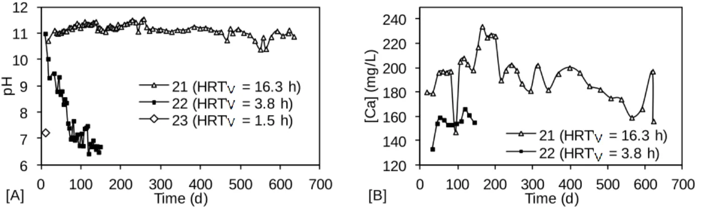
3.3.2 Column set 2 ... 28
3.3.3 Precipitate characterization ... 29
3.4 Toxicity tests ... 32
CHAPTER 4 MODEL OF PHOSPHORUS PRECIPITATION AND CRYSTAL FORMATION IN ELECTRIC ARC FURNACE STEEL SLAG FILTERS (ARTICLE) ... 34
4.1 Introduction ... 34
4.2 Materials and methods ... 36
4.2.1 Reactive media and reconstituted effluent ... 36
4.2.2 Column tests ... 36
4.2.3 Analytical determinations ... 37
4.3 Results ... 37
4.4.1 Slag dissolution and role of pH ... 41
4.4.2 Water velocity and crystal behavior in the filter ... 42
4.4.3 Proposed conceptual model ... 44
4.4.4 Parameters that influence crystal accumulation and organization ... 46
4.4.5 A new approach for the expression of phosphorus retention capacity ... 47
4.4.6 Practical recommendations ... 48
CHAPTER 5 TREATMENT PERFORMANCE OF SLAG FILTERS ... 50
5.1 Selection of media and treatment sequences ... 50
5.2 Efficiency and longevity of filters ... 51
5.2.1 Phosphorus removal ... 52
5.2.2 Fluoride removal ... 54
5.2.3 Metals removal ... 57
5.2.4 Performance goals ... 57
5.2.5 Crystal growth ... 58
CONCLUSION AND RECOMMENDATIONS ... 63
REFERENCES ... 68
LIST OF TABLES
Table 1.1 : Comparison of prediction tools efficiency for different treatment slag processes ... 13
Table 2.1 : Average composition of the reconstituted effluents ... 15
Table 2.2 : Tested slags and apatites ... 16
Table 2.3 : Chemical composition of tested slags ... 17
Table 2.4 : Mineralogical composition of slags ... 17
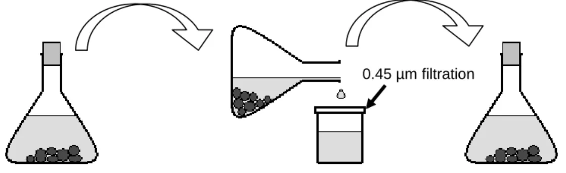
Table 2.5 : Summary of column tests parameters ... 20
Table 2.6 : Joplin performance goals, acceptable effluent limits and maximum TCLP concentrations for a non toxic media (Environmental Health and Satefy Online, 2008) ... 22
Table 3.1 : Qualitative comparison of individual batch tests using WW 1. Significant observations are highlighted ... 23
Table 3.2 : Qualitative comparison of individual batch tests using WW 3. Significant observations are highlighted ... 23
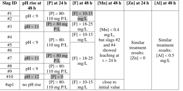
Table 3.3 : Qualitative comparison of sequential batch tests ... 25
Table 3.4 : Precipitate sampling and characterization ... 30
Table 5.1 : Contaminant retention for Joplin column tests ... 51
Table A.1: Individual batch tests results (tests in WW 1) ... 73
Table A.2: Individual batch tests results (tests in WW 1) ... 74
Table A.3: Individual batch tests results (tests in WW 3) ... 75
LIST OF FIGURES
Figure 2.1 : Origin of tested materials. (map: http://litlink.ket.org/stations/stationshome.aspl) .... 16
Figure 2.2 : Individual batch tests experimental setup ... 18
Figure 2.3 : Sequential batch tests experimental setup ... 18
Figure 2.4 : Column tests experimental setup ... 19
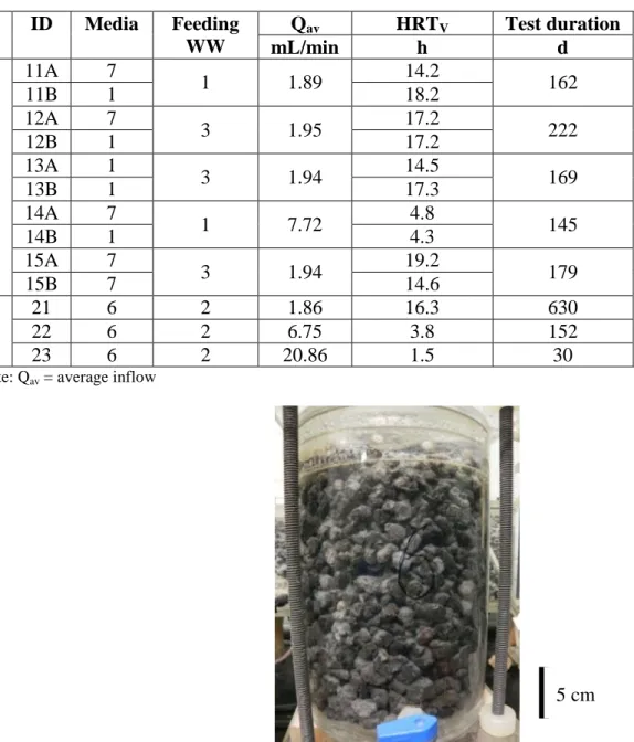
Figure 2.5 : Example of a 3-liter column filled with slag. ... 20
Figure 3.1 : Sequential batch tests results ... 24
Figure 3.2 : pH monitoring of column effluents, set 1 ... 25
Figure 3.3 : Calcium monitoring of column effluents, set 1 ... 26
Figure 3.4: ortho-phosphates monitoring of column effluents, set 1 ... 26
Figure 3.5: Fluoride monitoring of column effluents, set 1 ... 27
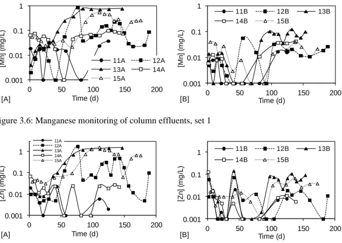
Figure 3.6: Manganese monitoring of column effluents, set 1 ... 27
Figure 3.7: Zinc monitoring of column effluents, set 1 ... 28
Figure 3.8: Aluminum monitoring of column effluents, set 1 ... 28
Figure 3.9 : pH and calcium monitoring of column effluents, set 2 ... 28
Figure 3.10 : ortho-phosphates and fluoride monitoring of column effluents, set 2 ... 29
Figure 3.11 : Manganese and zinc monitoring of column effluents, set 2 ... 29
Figure 3.12 : Theoretical diffractograms of HAP and calcite ... 31
Figure 3.13 : Comparison of HAP / calcite proportions in XRD diffractograms based on intensity of two characteristic peaks. No calcite visible and HAP predominant (A); HAP predominant and calcite present (B); calcite predominant and HAP present (C) ... 31
Figure 3.14 : Results of toxicity tests in distilled water for major compounds (A), iron (B) and trace compounds (C) ... 32
Figure 3.15 : Results of toxicity tests in acetic acid for trace compounds (A), major compounds (B) and calcium (C) ... 32
Figure 4.1 : Relationship between effluent pH and normalized effluent o-PO4 (influent [o-PO4] =
26 ± 2 mg P/L) ... 38 Figure 4.2 : Phosphorus removal efficiency at different HRTV expressed in traditional mg P / g
slag (A) and newly proposed mg P / mL voids (B). The duration of the experiment is indicated besides the last data point presented ... 39 Figure 4.3 : Progression of the precipitate bed within the HRTV = 16.3 h column. The position of
the reaction front was determined visually ... 40 Figure 4.4 : Photo of white crystals (>95% apatite confirmed by X-ray diffraction) formed on
cavity wall (A); TEM photo of apatite crystal aggregate (B); TEM photo of acicular apatite crystals (C); TEM photo of a crystal seed with fibrous aspect (D) ... 40 Figure 4.5 : Effect of water velocity on phosphorus retention capacity ... 42 Figure 4.6 : Crystal growth observed in filters (three data points for three different filters). Mean
crystal size was determined by XRD and Vw stands for water velocity ... 43
Figure 4.7 : Conceptual representation of a compact (left) and a loose (right) crystal organization in a slag filter. The mass of apatite crystals in the filter is considered identical in both filters ... 45 Figure 5.1 : Column tests experimental setup ... 52 Figure 5.2 (suite): Relationship between effluent o-PO4 concentration and pH ([A] in logarithm
scale, [B] in arithmetic scale) ... 54 Figure 5.3 : Relationship between fluoride and pH in column effluent ... 55 Figure 5.4 : Effluent concentrations of an efficient slag filter (two successive Fort Smith EAF
slag filters operated at total HRTV of 34 h) compared with Joplin project performance goals,
actual effluent concentrations of the lime treatment plant and selected regulations ... 58 Figure 5.5 : Relationship between calcium and pH at columns’ effluent. Ca, inlet refers to the
initial concentration in WW (WW 1, 2 or 3). Ca, outlet refers to the concentration at each column’s effluent ... 59 Figure 5.6 : Hydroxyapatite growth in upstream filters ... 60
Figure 5.7 : Comparison of HAP and calcite crystal sizes. For each point, sizes are computed from the same diffractogram. The height of the sample in the column is given at the right of
each point (cm) ... 62
Figure B.1 : Phosphorus retention capacities of upstream filters (set 1 only) ... 77
Figure B.2 : Fluoride retention capacities of upstream filters ... 77
Figure B.3 : Manganese retention capacities of upstream filters ... 78
Figure B.4 : Zinc retention capacities of upstream filters ... 78
ACRONYMS AND SYMBOLS
Acronyms:ANC curves Acid neutralizing capacity curves
ASTM American Society for Testing and Materials EAF Electric arc furnace
FAP Fluoroapatite HAP Hydroxyapatite
HRTV Void hydraulic retention time
MDDEP Ministère du développement durable, de l’environnement et des parcs du Québec NSA National Slag Association
TCLP Toxicity characteristic leaching procedure TEM Transmission electronic microscope
USEPA United States Environmental Protection Agency
WW Wastewater
XRD X-Ray diffraction
Symbols:
mmedia mass of the slag media in a column, g
Qav average influent flowrate in a column, mL/min
Vc volume of a column, mL
Vvoid void volume in a column, mL
LIST OF APPENCIDES
APPENDIX A INDIVIDUAL BATCH TEST RESULTS ... 73 APPENDIX B RETENTION CAPACITY OF FILTERS ... 77
INTRODUCTION
Context and objectivesAbandoned mining sites have a significant impact on the environment. Major alterations on the landscape are added to direct pollution of surrounding water streams by mining leachates. In this project, the focus of the investigation was an abandoned gypsum mining site located in Joplin, Missouri. High concentrations of various contaminants (phosphorus, fluoride and metals) were present in nearby water streams. This site was previously managed by the implementation of a chemical treatment plant, which is currently in operation. The mining leachate is collected and treated with lime addition, which precipitates contaminants. However, this system does not meet the latest discharge regulations. In particular, the presence of phosphorus at the treatment plant effluent is a major concern because it favours eutrophication even at very low concentrations. Implementing an economical technology that both reduces phosphorus concentrations enough to avoid eutrophication and removes typical heavy metals present in the mining leachates is a challenge.
The Missouri Trust decided to invest in a new treatment plan that would be economical and more efficient than the existing treatment plant. In that context, two engineering firms and one institution were hired to conduct that project: Shaw Environmental, Naturally Wallace Consulting and Polytechnique Montréal. In a preliminary analysis, steel slag filters were selected as promising treatment systems for this specific application. Polytechnique Montréal was mandated via this master project to conduct the first part of the project.
Objective 1: Propose, on the basis of lab-scale tests, a slag filter treatment system suitable for the treatment of the Joplin mining leachate. The proposed system has to meet new discharge criteria and be economical.
The hypothesis of this objective is that a correctly optimized slag filter is more efficient and economical than the existing chemical treatment plant. Filter parameters that need to be optimized are: slag type, hydraulic retention time and filter sequences.
A second problem was addressed in that master thesis project. Phosphorus treatment by slag filters is a well documented issue, but performances are variable between different studies. To this day, no efficient performance prediction tools exist for slag filters and the performance
has to be assessed by pilot tests. A global understanding and conceptualization of involved phenomena in slag filters is needed to develop such prediction tools.
Objective 2: Propose a preliminary model of phosphorus removal mechanisms in steel slag filters.
A new hypothesis has been formulated: a model based on crystal formation and accumulation in slag filters improves the actual understanding of phosphorus removal mechanisms and leads to more reliable prediction tools.
Content of this master thesis
In the literature review section, a summary of slag applications for wastewater treatment is presented, including phosphorus treatment, fluoride treatment and metal treatments. A synthesis of involved mechanisms in slag filters and actual prediction tools follow. Two chapters are devoted to the methodology and results. Several paragraphs of Chapters 1 and 2 were reproduced from the article «Steel slag filtration for extensive treatment of mining wastewater», presented at the 2011 WEFTEC congress1.
The discussion is divided in two chapters. The first one is the reproduction of the article «Model of phosphorus precipitation and crystal formation in electric arc furnace steel slag», published in Environmental Science and Technology in 2012. In this chapter, a preliminary model for phosphorus removal mechanisms is presented. The second discussion chapter addresses the need for a new treatment plan at the Joplin mining site and adds complementary information to the preliminary model. Finally, recommendations for the implementation of pilot tests at the Joplin mine and for the refinement of the phosphorus retention mechanisms model are given in the last section.
The article presented in this master thesis2 played a major role in the evolution of this project. It provides answers to the second objective formulated above. The ideas leading to the
1 Claveau-Mallet, Dominique; Wallace, Scott and Comeau, Yves. (2011). Steel slag filtration for extensive treatment
of mining wastewater. Paper presented at the WEFTEC congress, Los Angeles, California, October 15-19.
2 Claveau-Mallet, Dominique; Wallace, Scott and Comeau, Yves. (2012). Model of phosphorus precipitation and
article are presented in the literature review (Chapter 1). The methodology and results presented in the article are also presented and explained in Chapter 2 and Chapter 3, which are more complete and detailed.
CHAPTER 1
LITERATURE REVIEW
1.1 The mining leachate treatment challenge
Mining operations can have major impact on the environment, indirectly also affecting human health. In particular, site closure is a determinant step to limit long-term damage caused by mining leachates. Mining residual tailings are stocked in piles that can reach large dimensions. If rain and surface water are not well controlled, they may become contaminated while flowing in piles and being discharged in natural systems. Even if many modern mining companies take the responsibility to restore the site after the mine life, old orphan mining sites still exist and create contamination from mining leachates.
A frequent problem related to mining leachates is acid mine drainage. Sulphidic minerals contained in tailings react with air and water to form sulphuric acid (Demers et al., 2011). This reaction is fed by tailings during decades before the acidification process is extinguished. This acid leachate favours the dissolution of metals contained in the tailings, including heavy metals.
Mining leachates are controlled by two main technologies: passive covers or treatment of the leachate. These two technologies are fundamentally different. The purpose of passive covers is to limit interactions between the environment (water and air) and the tailings. In other words, passive covers minimize the leachate generation process. Multilayer soil covers were used in lab scale and full-scale applications to control acid mine drainage by limiting oxygen diffusion and water infiltration in tailings (Aubertin et al., 1996; Mbonimpa et al., 2003).
If passive covers are interesting treatment solutions, it is sometimes preferable for economic or technical reasons to accept the leachate formation and treat it before it is discharged in the environment. Treatment reactors may be chemical or biological systems. As an exemple, acid mine drainage can be treated by sulphate reducing bacteria, which cause precipitation of heavy metals as sulfur minerals (Neculita, Zagury & Bussière, 2007).
The Joplin gypsum mine leachate has a particular composition. It contains typical high concentration of sulfates, but its pH is neutral. As a consequence, common and heavy metals are present, but in lower concentrations than what is seen in average acid mine drainage. The leachate contains high concentration of phosphorus (up to 110 mg P/L). In this specific case, phosphorus removal is a priority to avoid eutrophication of downstream water streams. The
Missouri Trust, the authority responsible for the Joplin site restoration, chose to investigate the treatment of the mine leachate with a reactive slag filter and to prioritize on phosphorus removal.
1.2 What is slag ?
Slag is a waste material produced in iron and steel mills. When the original ore is melted, metallic and non metallic components are separated. The artificial lava floating over melted iron is recovered and cooled, resulting in slag. Different varieties of slag exist, depending on the metallurgical process it comes from. Two main types of slag are identified by the American National Slag Association (NSA): blast furnace slag and steel slag (NSA, 2009). Blast furnace slag is produced from iron mills, where iron ore, flux stone (calcium rich stone) and coke react in a blast furnace. Its main components are silica oxides, alumina, lime and magnesia. Steel slag is produced from basic oxygen furnace (BOF slag) or electric arc furnace (EAF slag), where iron and scrap are processed with lime. Its main components are calcium silicates, aluminoferrites and oxides of calcium, iron, magnesium and manganese. Three types of slag shapes are produced (air cooled, expanded or granulated). Cooling processes determine the porosity and crystalline fraction of slag. Finally, crushing and/or sieving result in different slag grain size, from powder to coarse aggregates.
Slag is used in numerous applications. Depending of its properties, it is used for pavements, concrete, bituminous pavements, railroad ballasts, roofing aggregates, mineral wool insulation, floor fill, highway base, agricultural liming, unpaved parking or roads and wastewater treatment (NSA, 2009). When slag is used for an environmental purpose, its leaching behavior has to be carefully tested and certified as environmentally safe. Leaching of heavy metals is a crucial concern. However, data concerning slag indicate that many slags in North America are considered non hazardous waste and can be safely used (Proctor et al., 2000).
1.3 Wastewater treatment by slag
There are two different manners to use slag for wastewater treatment. Powdered or small sized slag can be a sorbent in a completely mixed system (jar tests, adsorption isotherms) or granular slag may constitute the media in a filter. Both systems have their advantages and limitations. Granular filters are simple, economical and extensive compared to sorption systems that involve maintenance and complexity (continuous feeding with slag media, energy need for
mixing, sludge disposal, need of a settling or filtration unit). On the other side, sorption systems are more reliable than granular filters because they do not clog and treatment performances are easily determined by adsorption isotherms.
In the literature, treatment performances are presented with both concepts: adsorption isotherms or filter performance (removal efficiency). However, these two approaches are often used without distinction even if they are fundamentally different. Authors of recent literature reviews outline the difficulty to correlate treatment performances between different studies when both methodologies are employed (Chazarenc et al., 2008; Vohla et al., 2001). Adsorption isotherms have been used to predict the treatment performance of filters, but this prediction method was shown to lead to incorrect results (Chazarenc et al., 2008; Drizo et al., 2002). In this study, the filter approach is used, as we were interested in extensive treatment systems. Preliminary adsorption jar-tests are used for comparative purposes.
1.3.1 Phosphorus treatment
Phosphorus is the principal contaminant treated by slag, as confirmed by the many studies devoted to that topic (Chazarenc et al., 2008; Vohla et al., 2001). The treatment performances of slag for phosphorus removal have been studied using short-term batch tests, column tests or field-scale tests. Short-term batch tests remain the most well documented approach (Chazarenc et al., 2008), but focus will be given to column and field-scale filters in the next paragraphs.
Different types of wastewater have been treated in recent slag column or field-scale applications. Baker, Blowes and Ptacek (1998) operated slag columns during 4 years and achieved 90% phosphorus removal with hydraulic retention time of voids (HRTV) of 0.9 day.
Smyth et al. (2002) used slag in soil to intercept a contaminant plume from a septic tank. He monitored his system with piezometry during 2 years. He reached a phosphorus concentration of 0.05 mg P/L at the outlet. He also performed column tests for 8 years with an outlet phosphorus concentration of 0.3 mg P/L after that period. Chazarenc, Brisson and Comeau (2007) tested slag columns at the outlet of constructed wetlands. They reported 75% phosphorus removal in one year of operation. Koiv et al. (2010) reported efficient phosphorus removal from pre-treated domestic wastewater and landfill leachates. In New-Zealand, slag filters were operated for more than 5 years as post-treatment of domestic wastewater treatment ponds (Pratt & Shilton, 2010).
Recently, a pilot slag filter in a fish farm resulted in more than 97% phosphorus removal from the sludge in several months of operation (Brient, 2012).
Some specific properties of slag filters have been addressed in recent studies. Regeneration of slag filters after drying was shown to be possible by Drizo et al. (2002), who increased her column retention capacity from 1.35 to 2.35 mg P / g of slag with this process. The hydraulic retention time of slag filters has a direct impact on their removal performances (Liira et al., 2009; Shilton et al., 2005). Some authors highlighted important differences between short term tests and pilot tests performance results. Shilton et al. (2005) reported that full-scale tests gave higher removal performances than similar tests conducted in columns, possibly because of the influence of algae. Pratt and Shilton (2010) suggested that short-term batch tests are not suitable to characterize performances of slag filters even if phosphorus is treated by adsorption, because long-term slag alteration creates new adsorption sites. The major difficulties related with slag filters are clogging and decline of efficiency after 6 months (Chazarenc et al., 2008). Finally, the formation of hydroxyapatite was observed by many authors when the effluent pH of filters is high (Chazarenc et al., 2008; Vohla et al., 2011).
1.3.1.1 Phosphorus recovery
Phosphorus in wastewater is a contaminant, but it is also a nutrient. Phosphorus recovery from wastewater is possible by precipitation of phosphate phases, which have economical value for the fertilization industry. Phosphorus is generally recovered in a dedicated process, mainly fluidised beds involving chemical additives (Valsami-Jones, 2001). Phosphorus is precipitated and recovered on seeds. Steel slag filters offer promising phosphorus recovery applications because phosphorus precipitation in stable phases occur within these filters. A used filter that includes both phosphorus and calcium source could be used directly as a fertilizer.
1.3.2 Fluoride and metals treatment
As presented in a preceding section, wastewater treatment by slag involves two main applications: adsorption batch processes and filters. While both approaches have been studied for phosphorus removal, fluoride was mainly treated with batch processes. Fluoride removal from drinking water was studied by adsorption on various media such as coal fly ash or natural mud (Chen et al., 2010; Lu, Wang & Ban, 2010; Xue & Ma, 2009). Adsorption on slag was also used
for wastewaters with higher fluoride concentration (Huang, Shih & Chang, 2011; Xu et al., 2011). Fluoride removal by precipitation (mainly as CaF2) was tested with chemical additives
such as CaF2 or CaF2-Al(OH)3 seeds (Yan et al., 2001) or in fluidized bed of silica sand (Aldaco,
Irabien & Luis, 2005). Several specific industrial wastewaters (semiconductor manufacturers and electronic industries) contain both high fluoride and phosphorus, which reduces the removal efficiency of fluoride by CaF2 formation (Warmadewanthi & Liu, 2009). Some authors reported
selective precipitation of phosphorus or fluoride from wastewater (Grzmil & Wronkowski, 2006; Warmadewanthi & Liu, 2009; Yang et al., 2001). All these processes for fluoride removal were efficient, but involved the continuous addition of chemicals and the production of chemical sludge that was expensive to manage and required significant maintenance.
The use of slag for the treatment of metals was well documented in a recent critical review (Zhou & Haynes, 2010). Slag was mainly studied as an adsorbent in single-metal contaminant batch tests and characterized with Langmuir or Freundlich equations (Beh et al., 2010; Huifen et al., 2011; Sheng-Yu et al., 2009; Wang & Lin, 2010). Slag columns were operated for metal removal with a resulting arsenic effluent concentration of 0.003 mg/L (Smyth et al., 2002). Low concentrations of metals (Cu, Mg, Mn, Ni, Zn) in domestic wastewater were removed with slag filters (Renman et al., 2009).
Metal removal with slag may be compared with chemical precipitation of metals. Most of heavy metal hydroxides have minimum solubility between pH of 9 and 12 (Metcalf & Eddy, 2003), which is the typical pH range of an efficient slag filter.
1.4 Phosphorus removal mechanisms in slag filters and proposed models
In the beginning of this chapter, a major problem concerning prediction tools for treatment performances of slag was outlined. Three different methodologies – batch tests, column tests and pilot tests – were indistinctly used to explain two different phenomena – adsorption and precipitation. Moreover, the limit between adsorption and precipitation/crystallization is not clear. Adsorption is the first step of every nucleation seed formation. The relative importance of adsorption and precipitation depends on pH. Adsorption dominates at low pH and precipitation at high pH (Baker, Blowes & Ptacek, 1998). The complexity of systems (water composition, presence of nucleation seeds, hydraulics, etc.) makes the situation difficult to generalize, so that adsorption may occur as much as precipitation. Slag itself adds complexity to the situation: theircomposition are so different depending on the natural ore, type of furnace, type of cooling process and used additives that there is no direct relationship between slag type and removal efficiency. In general, blast furnace slags are more efficient than steel slags (Vohla, 2011).
In this master thesis framework, the focus was be given to prediction tools for alkaline slag filters. These are defined as a fixed granular media that increases the pH of the water that flows through it. Such a filter involves seven phenomena :
- Diffusion. Dissolved ions from the slag surface migrate in the water via diffusion. Diffusion may be slowed by the presence of accumulated matter.
- Adsorption. Adsorption is the adhesion of free ions or molecules in the solution on a solid particle. Adsorption is controlled by surface energy, may be reversible and may be influenced by inhibitors. Adsorbed ions or molecules may be bound to adsorption sites by week or strong chemical links.
- Nucleation. Nucleation is the amorphous formation of a solid phase nucleus. It may occur on a pre-existing surface or freely in a solution. The nucleation rate is dependent on many factors (catalytic pre-existing surfaces, adsorbed ions on these pre-existing surfaces, composition of water, etc.)
- Crystal growth. Crystal growth is the progressive formation of organized solid phases. Crystal growth is a surface phenomenon as free ions join pre-existing crystal or nucleus. Crystal growth rate is generally different from nucleation rate and it also depends on environmental factors (geometry and composition of pre-existing crystal or seeds, adsorbed ions on these pre-existing surfaces, composition of water, etc.) - Crystal reorganisation. Pre-existing solid phases (amorphous seeds or crystals) may
reorganise and transform into a more stable phase.
- Filtration. Filtration occurs in slag filters because direct nucleation within the solution is possible. Newly formed seeds are either retained by slag particles or other fixed crystals and seeds. They also may be washed out if hydrodynamic conditions favour it. Wastewater suspended solids containing organic matter may also be retained by direct filtration, increasing the rate of filter clogging.
- Settling. If water velocity, turbulence conditions and crystal size allow it, crystals may settle within the filter.
The term «precipitation» is a general one that includes both nucleation and crystal growth. Existing prediction tools are based on one or more of these phenomena, but not necessarily all of them. In the next lines, these prediction tools are shortly presented. They are divided in two main categories which are models based on chemical equilibria, and models based on chemical kinetics.
1.4.1 Models based on chemical equilibria
Models based on chemical equilibria assume that the system has reached steady state conditions. The major problem with these models is that the rate of kinetic reactions is very important in precipitation processes. When precipitation occurs, the final chemical species present in a given solution are often better described by kinetics and not by equilibrium (Valsami-Jones, 2001). This is especially true when we are dealing with geological reactions (transformation of gypsum to anhydrite, formation of calcite, etc.).
1.4.1.1 Adsorption capacity of slag (mg P / g of slag)
This is the main ratio currently used to characterize the treatment performance of slag. Its principle is simple: the slag has a maximum retention capacity that is reached after all its adsorption sites are occupied. This value is simply determined by classical adsorption isotherms in batch tests. However, it considers only adsorption among the seven involved phenomena. This is why adsorption isotherms from batch tests are unreliable for the prediction of slag filter performance (Drizo et al., 2002).
1.4.1.2 Phosphorus fractionation
This method is used to characterize the phosphorus potential for reuse as a fertilizer (Drizo et al., 2002; Pratt & Shilton, 2010). It describes the proportion of phosphorus bound to different ions (calcium solids, iron-bound, etc.) This method is not a direct prediction tool for performance, but it provides information about phosphorus reactions in slag filters.
1.4.2 Models based on chemical kinetics
Models based on chemical kinetics consider reaction rates, which is essential for a better understanding of the seven phenomena involved in slag filter treatment. They are more complicated than models based on equilibrium, but they give more realistic predictions. Unfortunately, the several existing models based on kinetics explain only a part of what happens in slag filters.
1.4.2.1 Studies of slag behavior
Slag particles are directly responsible for adsorption and filtration, and they modify the water composition, which leads to precipitation mechanisms. Microscopic photography of slag surfaces was performed by some authors (Koiv et al., 2010; Pratt & Shilton, 2010), allowing qualitative description of the interaction between slag surfaces and crystal formation. An alteration of slag surfaces over time was reported by Bowden et al. (2009), highlighting that crystal formation processes change with time.
Slag leaching of calcium and hydroxides within the wastewater is responsible for precipitation mechanisms (Claveau-Mallet, Wallace & Comeau, 2012). pH-rise kinetics was studied in batch tests and modeled with classical kinetic models, such as the intra-particle diffusion or the pseudo-second-order model (Chazarenc et al., 2008). Acid neutralizing capacity curves (ANC curves) were proposed to describe the slag potential for pH rise (Kostura, Kulveitova & Leko, 2005). This author related ANC curves to the successive dissolution of different mineralogical phases within slag. ANC curves are promising tools to predict the long-term capacity of slag to increase pH, but still don’t consider kinetics.
1.4.2.2 Studies of hydroxyapatite formation and growth
Studies concerning hydroxyapatite (HAP) formation and growth are numerous. Needs from different applied science branches (wastewater treatment, mineralogy and crystallography, biomedical, ceramics) have resulted in various results, often presented with different approaches. HAP is known to be the final crystallographic phase of other metastable calcium phosphates as monetite, octacalcium phosphate, tricalcium phosphate or amorphous calcium phosphate (Valsami-Jones, 2001). Two nucleation processes are possible: homogenous - directly from aqueous species - or heterogenous - on surfaces or seeds (Valsami-Jones, 2001). These nucleation
processes have great importance in phosphorus recovery from fluidized beds, where heterogeneous nucleation must be favoured. HAP formation was observed in supersaturated solutions because ionic association effects limit the contribution of aqueous species to saturation (Baker et al., 1998; Valsami-Jones, 2001).
The water composition affects HAP formation. HAP nucleation and growth rates are influenced by major ions concentration as calcium, hydroxides and phosphorus (Tsuru et al., 2001). Metallic ions may catalyze or inhibit nucleation or growth of HAP (Lundager Madsen, 2008) and also affect crystal shapes. Carbonates are growth inhibitors because they attach to growth surfaces (Valsami-Jones, 2001) or contribute to calcium carbonate formation, as competitive processes (Liira et al., 2009). HAP precipitation was diminished in water with low concentration of phosphorus (Koiv et al., 2010).
The transformation of HAP into fluoroapatite (FAP) by ionic migration of fluoride ions into the apatite structure has been theoretically demonstrated (Jay, Rushton & Grimes, 2012). These authors showed that fluoride migration is possible only over 1100 K, suggesting that HAP cannot transform to FAP at ambient environmental temperatures.
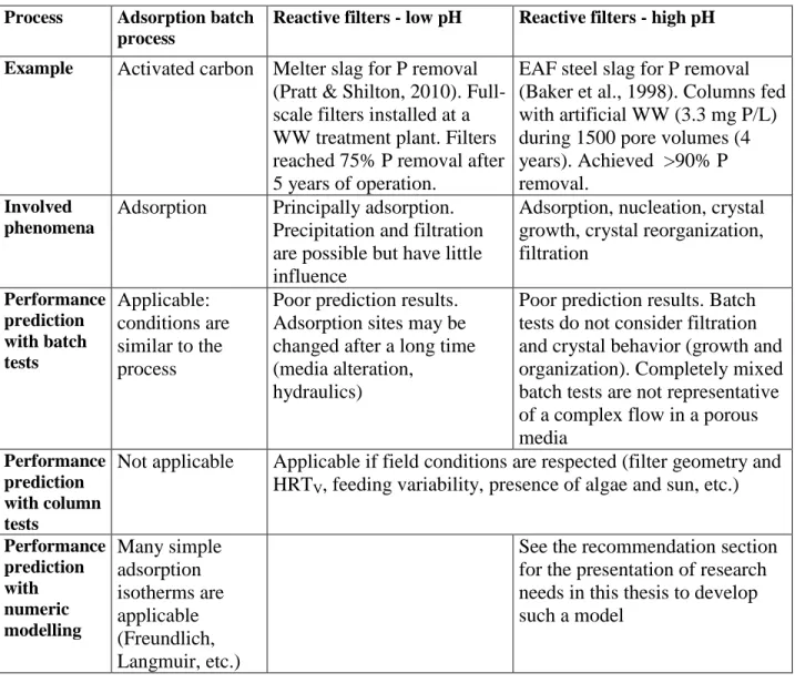
1.4.3 Summary of prediction tools for slag processes
A summary of prediction tools for three different slag processes in presented in Table 1.1. An emphasis is given to the last column which describes alkaline reactive filters.
Table 1.1 : Comparison of prediction tools efficiency for different treatment slag processes
Process Adsorption batch
process
Reactive filters - low pH Reactive filters - high pH
Example Activated carbon Melter slag for P removal
(Pratt & Shilton, 2010). Full-scale filters installed at a WW treatment plant. Filters reached 75% P removal after 5 years of operation.
EAF steel slag for P removal (Baker et al., 1998). Columns fed with artificial WW (3.3 mg P/L) during 1500 pore volumes (4 years). Achieved >90% P removal.
Involved phenomena
Adsorption Principally adsorption. Precipitation and filtration are possible but have little influence
Adsorption, nucleation, crystal growth, crystal reorganization, filtration Performance prediction with batch tests Applicable: conditions are similar to the process
Poor prediction results. Adsorption sites may be changed after a long time (media alteration,
hydraulics)
Poor prediction results. Batch tests do not consider filtration and crystal behavior (growth and organization). Completely mixed batch tests are not representative of a complex flow in a porous media
Performance prediction with column tests
Not applicable Applicable if field conditions are respected (filter geometry and HRTV, feeding variability, presence of algae and sun, etc.)
Performance prediction with numeric modelling Many simple adsorption isotherms are applicable (Freundlich, Langmuir, etc.)
See the recommendation section for the presentation of research needs in this thesis to develop such a model
Table 1.1 shows how prediction of slag processes performance may be challenging. Phosphorus removal is achieved by different phenomenon depending if water is neutral or alkaline, and the difference between these two environments is not well defined. Complex long-term field conditions as slag alteration or alga presence may modify the slag capacity for treatment. Finally, numerical modelling is currently used only for adsorption batch processes.
CHAPTER 2
MATERIALS AND METHODS
The experimental program included three parts: individual batch tests, sequential batch tests and column tests. Individual batch tests were used to compare the treatment potential of different media and select the most efficient media. Sequential batch tests are a slightly modified version of the individual batch tests, where different treatment sequences of slag are compared. Finally, column tests are used to characterize the treatment performances and longevity of lab-scale slag filters. Column tests were divided in two sets. The first set of tests was conducted with the best media and sequences selected from the first two parts. The second set of tests was used to develop a preliminary model for phosphorus removal mechanisms. A detailed description of the three experimental phases is given below, preceded by the description of the reconstituted wastewater (WW) and media used in the experimental program. The subsequent section describes analytical determinations used in the three parts of the experimental program. The last section describes toxicity tests that were performed on the media used in column tests.
The present chapter includes the methodology section described in the article of Chapter 4, which corresponds to the second set of column tests.
2.1 Reconstituted wastewater and tested media
Tests were conducted with three reconstituted mine effluents, WW 1, 2 and 3 representing, respectively, the minimum, mean and maximum concentrations observed at the Joplin site. WW 1 and 3 were used in the first set of column tests and WW 2 was used in the second set. These effluents were prepared using laboratory-grade salts (e.g. KH2PO4, CaCl2,
MnSO4, etc.) dissolved in tap water for WW 1 and 3 and distilled water for WW 2. Salts were
individually dissolved then mixed together. pH was adjusted to the field value with H2SO4 5N for
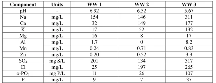
WW 1 and 3 and with NaOH 6N for WW 2. The solution was left to rest for at least 24 h to reach equilibrium (a small amount of precipitate formed during the mixing of individually dissolved salts) and settled. The supernatant was used in all tests. A sample of the initial solution was filtered and used for analytical characterization. The average composition of the reconstituted effluents is shown in Table 2.1.
Table 2.1 : Average composition of the reconstituted effluents Component Units WW 1 WW 2 WW 3 pH - 6.92 6.52 5.67 Na mg/L 154 146 311 Ca mg/L 32 149 177 K mg/L 17 52 132 Mg mg/L 16 8 17 Al mg/L 1.7 0 8.2 Mn mg/L 0.24 0.71 0.83 Zn mg/L 0.20 0.52 3.3 SO4 mg S/L 201 134 317 Cl mg/L 25 197 265 o-PO4 mg P/L 11 26 107 F mg/L 9 7 37
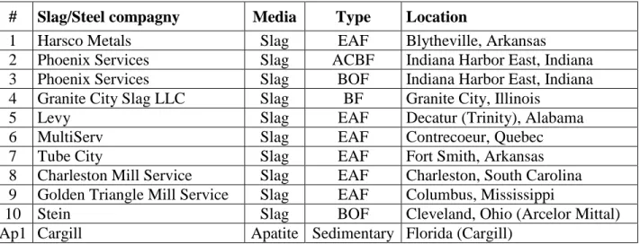
One type of apatite, nine types of slag from the United States and one type of slag from Quebec were tested (Table 2.2 and Figure 2.1). All slag samples were sieved to 5-10 mm, washed and air dried before utilization. The utilization of 5-10 mm slag was based on previous studies that compared the efficiency of coarse, 5-10 mm and fine grained slag (Anjab, 2009). 5-10 mm slag was shown to be an optimum compromise between reactive surfaces and hydraulic efficiency. Some slag samples had to be crushed to achieve 5-10 mm because of the original size of the material (slags #2, 3, 4, 8 and 9). The apatite sample was tested in batch tests without initial washing and sieving (5-20 mm). The chemical composition of tested slags is presented in Table 2.3. These analyses were performed by Acme Analytical Laboratories (Vancouver, BC) with ICP-emission spectrometry preceded by a LiBO2/Li2B4O7 fusion and dilute nitric digestion.
The mineralogical composition of slags used in column tests is presented in Table 2.4. Mineralogical composition was determined by X-ray diffraction (XRD) analysis in the Geology Department of Tartu University, Estonia.
Table 2.2 : Tested slags and apatites
# Slag/Steel compagny Media Type Location
1 Harsco Metals Slag EAF Blytheville, Arkansas
2 Phoenix Services Slag ACBF Indiana Harbor East, Indiana
3 Phoenix Services Slag BOF Indiana Harbor East, Indiana
4 Granite City Slag LLC Slag BF Granite City, Illinois
5 Levy Slag EAF Decatur (Trinity), Alabama
6 MultiServ Slag EAF Contrecoeur, Quebec
7 Tube City Slag EAF Fort Smith, Arkansas
8 Charleston Mill Service Slag EAF Charleston, South Carolina 9 Golden Triangle Mill Service Slag EAF Columbus, Mississippi
10 Stein Slag BOF Cleveland, Ohio (Arcelor Mittal)
Ap1 Cargill Apatite Sedimentary Florida (Cargill)
Note: ACBF: air cooled blast furnace slag; BF; blast furnace slag; BOF: basic oxygen furnace slag; EAF: electric arc furnace slag.
Figure 2.1 : Origin of tested materials. (map: http://litlink.ket.org/stations/stationshome.aspl) Mine at Joplin, MO Slag
Apatite
N
Table 2.3 : Chemical composition of tested slags Slag ID DL 1 2 3 4 5 6 7 8 9 10 SiO2 % 0.01 10.94 37.45 11.95 40.12 10.68 15.92 14.49 11.57 12.22 16.28 Al2O3 % 0.01 11.87 11.59 4.42 8.33 4.60 6.03 7.69 6.17 5.91 5.14 Fe2O3 % 0.04 29.50 0.69 35.18 0.76 42.48 33.08 25.20 40.45 35.67 18.21 MgO % 0.01 10.27 13.48 8.30 12.47 10.42 12.07 14.66 12.66 12.77 10.19 CaO % 0.01 31.67 34.85 37.25 36.76 28.10 30.16 28.75 27.00 28.32 40.60 Na2O % 0.01 0.06 0.46 0.05 0.23 0.03 0.08 0.06 0.04 0.02 0.05 K2O % 0.01 0.03 0.65 0.04 0.45 0.01 0.01 <0.01 0.01 <0.01 0.03 TiO2 % 0.01 0.50 0.49 0.60 0.33 0.47 0.99 0.37 0.51 0.53 0.44 P2O5 % 0.01 0.48 <0.01 0.68 0.01 0.60 0.28 0.31 0.59 0.52 0.47 MnO % 0.01 3.29 0.49 3.18 0.61 4.18 2.37 7.96 3.18 5.36 3.88 Cr2O3 % 0.002 0.675 0.006 0.185 0.011 0.858 0.578 1.094 0.887 1.179 0.406 Ba ppm 5 455 760 516 355 430 392 436 606 443 75 Ni ppm 20 <20 <20 <20 <20 <20 <20 103 <20 <20 24 Sr ppm 2 301 455 173 416 255 223 267 305 348 184 Zr ppm 5 194 187 497 194 111 255 1011 117 91 204 Y ppm 3 27 69 5 37 17 44 8 23 9 8 Nb ppm 5 182 6 238 30 239 109 180 216 429 93 Sc ppm 1 6 15 2 9 5 180 2 6 2 2 Total % 99.4 100.3 102.0 100.2 102.5 101.7 100.8 103.8 102.6 95.8 Note: 1% equals 10 000 ppm. DL for detection limit.
Table 2.4 : Mineralogical composition of slags
Slag ID 1 6 7 Proportion (%) Merwinite Ca3Mg(SiO4)2 9.2 ± 0.3 4.6 ± 0.2 3.9 ± 0.2 Wuesitite FeO 30.8 ± 0.2 45.5 ± 0.2 42 ± 0.2 C2S, beta Ca2SiO4 26 ± 0.3 23.8 ± 0.2 29.2 ± 0.2 C4AF Ca2Fe0.28Al1.72O5 3.5 ± 0.1 1.5 ± 0.1 3.5 ± 0.1 Mayenite Ca12Al14O33 4.7 ± 0.1 0.6 ± 0.1 2.7 ± 0.1 Gehlenite Ca2Al(Si,Al)2O7 2.1 ± 0.1 4.9 ± 0.1 0.9 ± 0.1 Periclase MgO 3.2 ± 0.2 0.7 ± 0.1 3.3 ± 0.1 Akermanite Ca2MgSi2O7 2 ± 0.1 1.3 ± 0.1 1.7 ± 0.1 Magnesioferrite MgFe2O4 14.9 ±0.1 5.6 ± 0.1 5.1 ± 0.1 Bredigite Ca14Mg2(SiO4)8 3 ± 0.2 11.4 ± 0.2 7.3 ± 0.2
Spinel, submagnesian MgAl2O4 0.5 ± 0.1 - -
Quartz SiO2 - - 0.4 ± 0.06
Total 99.9 99.9 100.0
2.2 Individual batch tests
Individual batch tests are short-term tests used to establish a comparative list of media in terms of treatment efficiency. A 35 g media sample was placed in a 1000 mL Erlenmeyer flask
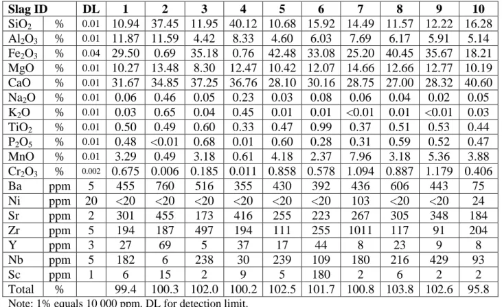
containing 700 mL of WW. The Erlenmeyer flask was shaken for 48 hours at 20°C and 170 rpm. Samples were taken after 0, 24 and 48 hours and filtered for the determination of P, F, Al, Mn, Zn and pH. WW 1 and 3 were tested for each media. A blank test containing the WW without media was conducted with each test group (7 tests including one blank sample conducted at the same time). Tests were run in duplicates. The experimental setup is shown in Figure 2.2.
Figure 2.2 : Individual batch tests experimental setup
2.3 Sequential batch tests
In sequential batch tests, different treatment sequences were tested. A 24 h individual batch test was performed with a first media and then the solution was filtered and used for a second individual batch test of 24 h with a second media. The treatment performance of a two-media sequence (24 h with first two-media and 24 h with second two-media) was compared with the treatment performance of a single-media system (48 h of the same media, as tested in individual batch tests). A blank test without media was conducted with each test group. Tests were run in duplicates. WW 3 only was used in sequential batch tests. The tested sequences and WW were chosen on the basis of individual batch tests results. This explanation is presented in section 5.1. The experimental setup is shown in Figure 2.3.
Figure 2.3 : Sequential batch tests experimental setup
700 mL WW
35 g slag sample
rubber cap
Gyratory shaker at 170 rpm and 20°C
Blank sample
Step 1: 24 h batch test with slag A Step 2: filtration of the WW Step 3: 24 h batch test with slag B
![Table 3.3 : Qualitative comparison of sequential batch tests Sequence ID pH rise at 48 h [P] at 24 h [F] at 48 h Mn removal [Zn] at 24 h Al removal #1-#1 pH = 8 [P] = 50-110 mg P/L [F] = 12-25 mg/L similar treatment results](https://thumb-eu.123doks.com/thumbv2/123doknet/2327349.30776/45.918.94.822.144.423/qualitative-comparison-sequential-sequence-removal-similar-treatment-results.webp)