HAL Id: hal-01709493
https://hal.archives-ouvertes.fr/hal-01709493
Submitted on 6 Mar 2019
HAL is a multi-disciplinary open access
archive for the deposit and dissemination of
sci-entific research documents, whether they are
pub-lished or not. The documents may come from
teaching and research institutions in France or
abroad, or from public or private research centers.
L’archive ouverte pluridisciplinaire HAL, est
destinée au dépôt et à la diffusion de documents
scientifiques de niveau recherche, publiés ou non,
émanant des établissements d’enseignement et de
recherche français ou étrangers, des laboratoires
publics ou privés.
Infrared curing simulations of liquid composites molding
Sawsane Nakouzi, J. Pancrace, Fabrice Schmidt, Yannick Le Maoult,
Florentin Berthet
To cite this version:
Sawsane Nakouzi, J. Pancrace, Fabrice Schmidt, Yannick Le Maoult, Florentin Berthet. Infrared
curing simulations of liquid composites molding. ESAFORM - 14th International Esaform conference
on material forming, Apr 2011, Belfast, United Kingdom. pp.1125-1130, �10.1063/1.3589667�.
�hal-01709493�
Infrared curing simulations of liquid composites molding
S. Nakouzi*, J. Pancrace, F.M. Schmidt, Y. Le Maoult, F. Berthet
Université de Toulouse ; INSA, UPS, Mines Albi, ISAE ; ICA (Institut Clément Ader); Campus Jarlard, F-81013 Albi cedex 09, France
Ecole des Mines Albi, Campus Jarlard, F-81013 Albi, France
Abstract : Infrared radiation is an effective energy source to cure thermosetting polymers. Its usage is expected to reduce curing time
in comparison with thermal heating and mold thermally regulated. In addition, because of the polymerization mechanism and instant on-off control of this power, an improvement in the final properties of the material is also expected. In this paper, we studied the infrared interaction with carbon (or glass) fibers reinforced epoxy matrix, where Liquid resin infusion (LRI) is used to manufacture the composite. Temperature of the composite is a key parameter that affects its mechanical properties and is controlled by the infrared emitters and the exothermic heat released from the polymerization. Radiative heat flux is computed using the in-lab developed software RAYHEAT. Then, the heat flux (or absorbed energy for glass fibers) is exported to the finite element based program COMSOLMULTIPHYSICS where heat balance equation is solved. This equation is coupled with the exothermic heat released during the curing process in order to predict the composite temperature versus time and degree of cure. Numerical simulations will be performed on planar parts (sheet shape) as well as curvilinear shapes. Experimental validations of the infrared curing carbon (glass)-epoxy composite system are presented in this paper Sheet surface temperature distribution are measured thanks to infrared camera. Kinetic parameters were estimated from differential scanning calorimeter (DSC) experimental data.
Keywords: Composite, Infrared curing, Curing optimization, Radiation, Glass/Epoxy, Carbon/Epoxy. Pacs:
INTRODUCTION
A novel process of curing composites is the use of infrared heaters. Carbon reinforcement epoxy matrix is cured in an infrared oven (figure 1) composed of halogen lamps.
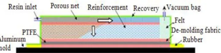
This manufacturing process is flexible: Emitter’s power which affects temperature distribution in the composite can be easily controlled. Different researchers 1 used IR radiation for curing thermosets, others 5 used it for the preheating process. In this study, Liquid Resin Infusion process is used to infuse the liquid resin (RTM6) through the reinforcement (figure 2).
IR OVEN
Composite is exposed to radiation in the infrared oven. This one is composed of nine halogen lamps provided by TOSHIBA LIGHTING company. Short wave halogen lamps (in the range 0.6 – 6µm and is the wavelength at the maximum lamp's relative intensity) made by TOSHIBA LIGHTING company were employed for perform the curing process. The lamps have variable power levels and a nominal power of 1000W. Tungsten filament is the infrared emitter. It is surrounded by quartz glass and a kind of halogen gas-filled lamp.
FIGURE 1 Schematic presentation of the Liquid Resin Infusion
process
FIGURE 3 Schematic presentation of the IR oven FIGURE 2 Infrared oven
Composite IR heater
Resin inlet Air aspiration
The infrared radiation is absorbed by the carbon ply present on the top surface of the composite, in addition this surface is a convective boundary surrounded by the air present in the oven Tair(t). Thermal insulation (Kerlane) is in contact
with the frame of the composite, the edge effect becomes negligibly small, that is we can ignore the heat exchanges all arround its contour. The bottom of the composite is in contact with a 12 mm thick PTFE block, this material was taken into account in the numerical simulations. we chose this in order to limit heat exanges with the aluminium mold and study the IR interactions. Bottom surface of the PTFE is in contact with the aluminium mold where its experimental temperature was introduced as a boundary conditions in the finite element software COMSOL. During curing, Incident radiation is absorbed by the top surface of the carbon/epoxy composite. Then the composite is thermally heated in the thickness via conduction from its top surface. Figure 4 presents the IR density distribution as well as the boundary conditions.
RAY TRACING METHOD
Thermal radiant heat flux upon the top surface of the composite is computed in MATLAB using the in-lab developed algorithms 7. Theses algorithms are based on ray tracing method. In ray tracing, we model radiation as rays of light. The propagation of the rays is only based on the laws of geometrical optics. The general idea consists to simulate the interactions between the ray of light emitted by a source (in our case halogen lamps) and every object present in the scene (Infrared oven): multiple lamps, reflectors, composite. In the ray tracing software, coiled tungsten is the infrared emitter. It is assumed to be a Lambertian grey body and it is modeled as a cylinder with equivalent diameter 8. That is, we define a number N of rays emitted from the lamp; this number is chosen in a way to have a good agreement between the calculations costs and the needed precision of the results. Cosson and al. [7] calculated the convergence of the radiative heat flux to the analytical solution [13], as a function of the number N of the rays. Then we start from a random point P on the infrared emitter and trace the ray emitted in a random direction. This direction is defined by two parameters and . These parameters are defined by stochastic variables:
where and are independent uniform stochastic variables 12 in the range .
Each ray emitted by the source is defined by its origin, direction, and spectral intensity. Then the ray is tested against all objects in the scene to determine what it hits and if it intersects the composite (fig. 5). The different interactions between the ray and the objects present in the scene change the ray properties. In our ray tracing software, assumptions found in the literature are made for the different optical properties of lamps, reflectors, recovery surface and the carbon/epoxy system. Ray tracing method was validated in an anterior work in the laboratorywith an analytical solution given by view factor 13.
W /m²
FIGURE 4 Boundary conditions
RADIATIVE PROPERTIES
A well known of the IR heat flux absorption on the top surface necessitate determination of the radiative properties for the sequence of plies: recovery surface film and de-molding fabric. Using an IR spectrometer, we measured radiative properties and determined the fraction of IR rays absorbed by the composite. Recovery surface transmit 85% of the infrared radiation to the demolding fabric (figure 6), than this one has high absorption spectral bands; 0.04% of the IR rays is transmitted to the composite (figure 7). In a second hand, spectral measurements in transmission for 1mm thick carbon fiber reinforcement sheet show that carbon reinforcement is optically opaque to the IR radiation (figure 8). These results were also found in the literature. To resume our spectral measurement, surface radiation transport occur on the top surface of the composite, our objective is to determine the ray fraction that is reflected when rays impact this surface. Spectral measurements in reflection for the sequence of the recovery surface film, the demolding fabric and the composite, compacted together, are plotted in figure 9. In the spectral range of the short wave halogen lamps, we assume a constant reflectanceand we take the mean value in the spectral band 0.6–6 μm (R= 12%).
Glass reinforcement as it is presented in the literature is optically transparent to the infrared radiation; this is not the case of our measurement in the spectral transmission band 1.3-25µm. As a first approach for the Glass reinforcement is opaque to the infrared radiation, in addition, the demolding fabric that is in contact with the fibers, transmit 0.04% of the infrared radiation to the reinforcement, that is, first approach that we can treat this case as a surface radiation transport.
MODEL DEFINITION
The composite measures 160 mm-by-140 mm and is 6 mm thick. The physics inside the composite14 is described by a heat balance (1) coupled with the exothermic heat (2) released during polymerization of epoxy matrix.
(1)
In the previous equation, denotes the thermal conductivity of the composite, equals the temperature, is the ultimate heat of reaction of the resin, is the degree of curing. The material property parameters required in this analysis are listed in table 1.
(2)
(3)
FIGURE 6 Spectral transmission of the recovery surface
FIGURE 7 Spectral transmission of the demolding fabric
FIGURE 9 Spectral reflection on the top surface (Recovery surface + demolding fabric + carbon fibers)
FIGURE 8 Spectral transmission of the carbon reinforcement
(4) (5)
Where is a diffusion factor, is diffusion rate constant with an Arrhenius type of dependence, is a constant having the order of one, the glass transition temperature, is a free volume fraction of the polymer, is a free volume fraction for a temperature equal to , is the thermal expansion coefficient. For an amorphous polymer which is the case of our composite, and .
TABLE 1 Thermo physical properties used in numerical simulations
Property Material Expression Reference
Volume fraction Carbon fiber
[17] RTM6 [17] Weight fraction RTM6 [16] Carbon fiber [16] Density Composite [16] Heat Capacity RTM6 (α=0) RTM6 (α=1) [18] [18] RTM6 (α) [18] Carbon fiber [18] Composite [18] Thermal conductivity RTM6 [18]
Carbon fiber 0.265 Transverse thermal conductivity ( [18] 3.1 Longitudinal thermal
conductivity (
[18] Composite
Transverse conductivity. thermal
[18]
Longitudinal thermal
conductivity.
[18]
EXPERIMENTAL
Experimental measurement was used to validate simulations of the whole Infrared curing composites process.
FIGURE 11 Schematic presentation of thermocouples at section A-A of the composite. FIGURE 10 Specific heat capacity of the carbon fiber reinforcement
In the experimental set up, carbon fibers placed in the mold were preheated by the infrared lamps present in the oven. Then the infrared heaters are turned off and the RTM6 resin at 80°C is infused through the reinforcement using the Liquid Resin Infusion process. In order to refer to the same operating conditions between experiments and simulations (we have not addressed in our simulations the filling step during which resin flows through the fiber reinforcement), infrared heaters are turned on after the infusion takes place and stabilization of the resin in the mold.
IR curing the composite is flexible and controllable; we controlled the heat flux in order to optimize a curing cycle. In another word, we imposed a high heat flux to initiate and accelerate reaction in the epoxy resin, and then the heat flux is turned off, every time when we reached 195°C (figure 15) in temperature (because the degradation temperature of the matrix is 220°C). Figure 12 shows the heat flux value imposed on the top surface of the composite (at the center).
The heat transfer coefficient, h, is obtained using a semi-empirical expression (from COMSOL library) as a function of temperature and distance from the leading edge of the composite (figure 14).
The bottom of the composite is in contact with a 12 mm thick Teflon block, which is in contact with the aluminium mold. Aluminium temperature was imposed as a boundary condition in the finite element software COMSOL MULTIPHYSICS.
Curing process is achieved with 47% of the nominal power of the infrared heaters. Because the degradation temperature of the matrix is 220°C, we turned off the lamps when we reached 195°C in temperature. Then the lamps were turned on when we decreased to 160°C in temperature. We introduced the experimental operating conditions as input data in our simulations: oven and composite geometry, air temperature, initial temperature of the composite, mold temperature.
SENSITIVITY ANALYSIS
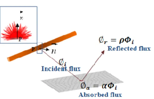
Because of carbon fibers embedded in the epoxy matrix are very strong IR absorbers at all wavelengths oh the IR spectrum , heat flux on the top surface of the composite is absorbed or reflected (figure 5), IR interaction with the composite is a surface radiation transport. The ray fraction absorbed by the composite is:
. (6)
FIGURE 12 Inward radiative heat flux on
composite top surface FIGURE 13 Oven air temperature FIGURE 14 Natural convection heat transfer coefficient
FIGURE 15 Experimental temperatures
FIGURE 17 Bottom temperature validation
Where is the mean reflectance, is the heat flux that impacts the top surface of the composite and is the heat flux absorbed by the composite. The heat flux absorbed by the composite is proportional to the reflectance of the top surface of the composite.
Sensitivity analysis were performed in the time range 0<t[s]<358 (the heat flux is turned off at t=358s, figure 12) in order to determine temperature sensitivity to the inward heat flux received on the top surface of the composite. Sensitivity of the composite temperature to the heat flux received on its top surface is calculated using equation 7:
(7)
From figure 19, we can deduce that composite temperature is very sensitive to the inward heat flux (which is proportional to the reflectance of the composite top surface) and is monitored by the infrared heaters.
CONCLUSIONS
Until now, we simulated the whole curing process of the carbon/Epoxy system, and we validated experimentally theses simulations, these results were presented previously. Numerical simulations for fast curing the thermoset polymers and their experiment validation results are presented in this paper. We presented also radiative properties measurements for the carbon fiber and glass fiber reinforcement, for the recovery surface and for the de-molding fabric.
In our future work, we will simulate the curing process of composites with an industrial geometry; a specific mold will be used in the Liquid Resin Infusion process.
ACKNOWLEDGEMENT
Financial support for this work was provided by TOSHIBA LIGHTING (France) Company. The authors are grateful to Mr. D. Goyot for his support and his attention to this work.
REFERENCES
1. B-C. Chern, T.J. Moon, J.R Howell, Journal of Composite Materials, 2002, 36, 1905. 2. B-C. Chern, T.J. Moon, J.R Howell, Journal of Composite Materials, 2002, 36, 1935. 3. B-C. Chern, T.J. Moon, J.R Howell, Journal of Heat Transfer, 1995, 117, 685. 4. B-C. Chern, T.J. Moon, J.R Howell, Journal of Heat Transfer , 2003, 125, 137. 5. S. Adanur, A. McClain and B. Xu, Journal of Elastomers and Plastics, 2003, 35, 257. 6. J. E. Cunningham ,P. F. Monaghan, M. T. Brogan, Composites Part A , 1998, 51, 61.
7. B. Cosson, F. Schmidt, Y. Le Maoult, M. Bordival, International Journal of Material Forming , 2010. 8. M. Bordival, Y. Le Maoult, F. Schmidt, Polymer Engineering & Science, 2009, 49, 783.
9. C. Champin, J. F. Agassant, M. Bellet, F.M. Schmidt, Y. Le Maoult, 20th International Conference of Polymer Processing
Society June 20-24, (Akron, Ohio, USA), 2004.
10. F.M. Schmidt, Y. Le Maoult, S. Monteix, Journal of materials processing technology, 2003,143, 225.
11. S. Andrieu, Y. Le Maoult, F.M. Schmidt , 18th International Conference of Polymer Processing Society, (Guimarès,
Portugal), 2002.
12. M. Pharr, G. Humphreys, Physically based rendering: from theory to implementation, Elseiver science USA, 2004. 13. H. Leuenberger, R.A. Person, ASME Annual Meeting, New York, 1956.
14. T-M-H. Nguyen, Systèmes époxy-amine incluant un catalyseur externe phénolyque: cinétique de réticulation-vieillissement
hydrolytique. Ph. D Thesis: Académie de Nice, Université du Sud Toulon, 2007. (In french).
15. J.M. Balvers, H.E.N. Bersee, A. Beukers, K.M.B. Jansen, Structures, Structural Dynamics, and Materials Conference,
Schaumburg, 2008.
16. E. Ruiz and F. Trochu, Journal of Composite Materials, 2005, 39, 881.
17. P.I. Panagiotis, I.K. Partridge, Journal of Apllied Polymer Science, 2000, 77, 1419.
18. D. Lecointe, Caractérisation et simulation des processus de transferts lors d'injection de résine pour le processus RTM. Ph. D Thesis: Ecole doctorale sciences pour l'ingénieur de Nantes, 1999. (In french)