HAL Id: hal-03118598
https://hal.archives-ouvertes.fr/hal-03118598
Submitted on 22 Jan 2021
HAL is a multi-disciplinary open access
archive for the deposit and dissemination of
sci-entific research documents, whether they are
pub-lished or not. The documents may come from
teaching and research institutions in France or
abroad, or from public or private research centers.
L’archive ouverte pluridisciplinaire HAL, est
destinée au dépôt et à la diffusion de documents
scientifiques de niveau recherche, publiés ou non,
émanant des établissements d’enseignement et de
recherche français ou étrangers, des laboratoires
publics ou privés.
Design and conception of an innovative packing for
separation column-Part I: Hydrodynamic study on wire
intersections
Baptiste Déjean, Michel Meyer, David Rouzineau
To cite this version:
Baptiste Déjean, Michel Meyer, David Rouzineau. Design and conception of an innovative packing for
separation column-Part I: Hydrodynamic study on wire intersections. Chemical Engineering Research
and Design, Elsevier, 2020, 160, pp.11-19. �10.1016/j.cherd.2020.05.006�. �hal-03118598�
Any correspondence concerning this service should be sent
to the repository administrator:
[email protected]
This is an author’s version published in:
http://oatao.univ-toulouse.fr/27266
To cite this version: Dejean, Baptiste and Meyer, Michel and
Rouzineau, David Design and conception of an innovative
packing for separation column—Part I: Hydrodynamic study on
wire intersections. (2020) Chemical Engineering Research and
Design, 160. 11-19. ISSN 0263-8762
Official URL
DOI :
https://doi.org/10.1016/j.cherd.2020.05.006
Open Archive Toulouse Archive Ouverte
OATAO is an open access repository that collects the work of Toulouse
researchers and makes it freely available over the web where possible
Design and conception of an innovative packing for
separation column-Part I: Hydrodynamic study on
wire intersections
Baptiste Dejean,
Michel Meyer,
David Rouzineau
*
Laboratoire de Génie Chimique, Université de Toulouse, CNRS, INPT, UPS, Toulouse, France
ABSTRACT
Keywords:
Hydrodynamic study Liquid flow on wire Innovative packing Separation column
Packed columns are crucial equipment established in the process industry in order to per form several separation operations (e.g. distillation, absorption, etc.). The scientific challenge is to improve the performance of these separation columns. This work aims to develop an innovative wire-based packing, where the liquid flow on the wire will have an interfacial surface greater than the geometric surface of the packing structure. A study of the liquid film behavior on inclined wires and their intersections is carried out based on experimen tal observations and a numerical simulation. The result is a mapping of the liquid flow regimes favored for the distillation process. Hence, it will be possible to orient the design of the wire-based packing, especially the wire diameter and inclination and the shape of the intersections.
1. Introduction
This study is part of the improvement of column packing for separa tion processes. For these applications, the best performances usually require packings with low-pressure drops, a good mass transfer effi ciency and a high capacity. During the past 40 years, numerous improvements were proposed. A short history is presented in the intro duction of the second part of this paper.
The idea of the present study is to develop a column packing com posed of a tangle of structured wires. The concept behind this idea is that the liquid flow on the wire will have a higher interfacial surface than the geometrical surface proposed by the packing structure itself. In opposition, for a packing based on plates, the liquid interfacial sur face will be equal more or less to the geometrical one (when neglecting the waves at the interface and the problems of wettability). Thus, for an identical geometrical surface for a wire and a plate based packing structure, the interfacial surface will be higher in the case of a wire if the liquid wets the entire surface. Therefore, in order to design a per forming based on wire packing, it is essential to study the liquid flow on wires and wire intersections.
The studies, which have worked on liquid flow on wires, are numer ous, but they focus on applications that are far from the present study. The first work focuses on micrometric fi.bers (under 100 µm), where
* Corresponding author.
E-mail address: [email protected] (D. Rouzineau).
Nomenclature P(r) V1 Qi t1 u(r) We y µ, p 0 inlet diameter, mm wire diameter, mm
ratio of wire diameter over capillary length F-factor, Pa0·5
acceleration due to gravity, m2/s capillary length, mm
wire length (i.e. the length of tetrahedron edges), mm
pressure, Pa
Volumetric flowrate, m3/s Mass flow rate, kg/s liquid fi.lm thickness, mm liquid velocity, m/s Weber number surface tension, mN/m dynamic viscosity, Pa.s density, kg/m3
angle between a wire and the vertical,
three different flow regimes are highlighted depending on these candi-tions: shell-shape, axisymmetric drops, and film (McHale and Newton, 2002}. In this case, the film regime is needed to prevent partial wetting
air outlet zone of _...,_1 interest airflow distributors liquid llectingtank '-:--,..
airflow
@
flowmeter/
r
'
.
..,...a,r pressure
needle
/
syringe pump
1
valve
! !
led panel/
humidifier ! i
connector
t
t
Fig. 1 - The experimental setup for the examination of liquid flow on wires and packing parts.
of the packing. However, the conditions for the appearance of each regime are not defined (Carroll, 1986, 1976, 1981), especially for liquid flowrates in separation columns. McHale et al. (2001, 2002) highlighted the influence of the contact angle on regime transition.
On the other hand, many works were developed on based fi.ber fi.1-ters (Mullins et al., 2004a and b) and water recuperation (Lorenceau et al., 2004). In these fields, the only papers that can be found on wire intersections are Gilet et al. (2009) and (2010), yet the wire diameter is usually micrometric and the intersections are perpendicular.
Finally, the studies on liquid flow instabilities are the closest to our current work concerning flowrates and characteristic sizes. In par ticular, Duprat (2009) observed the development of a destabilization length before the appearance of any instabilities on the liquid inter face. This length is always superior to 15 mm, which is greater than the wire length designed for the column packing. Moreover, the liquid flow on the based wire packings will not be subjected to destabi lizations that are observed on longer vertical wires. The same study suggested the use of Nusselt number to describe the liquid film thick ness before destabilization; this theoretical thickness will be compared to our measurements. The work also proposed a regime mapping, which highlights the different forces affecting the liquid flow: gravity, viscosity, inertia, and surface tension.
2.
Experimental test-rigIn order to examine the liquid flow on simple wires and pack ing parts, a test-rig was built as shown in Fig. 1. For an easy
wire-liquid -0 3 4 Ë 5
.s
6 7 ë 8 () 10 11:s
12�
13 14 15 16 17 18 19 20 2 3 4 5 6 8 Uquid film th,ckness (mm) Fig. 2 - The illustration of the image processing used to measure the liquid film thickness (left: real image, center: thresholded image, right: calculated liquid film thickness).optical access, the chamber has numerous square sections of 75 mm side length. A PHD 22/2000 syringe pump with two syringes of 60 mL is used to ensure the flow of the liquid up to 150 mL/min. A chuck is employed to hold the wire or pack ing parts and let the liquid flow surround the wire. The liquid inlet is designed to ensure a gravitational flow. At the liquid injection point, a connector can be switched in order to vary the initial liquid film thickness (injection diameter).
A countercurrent airflow can be generated through a nee dle valve coupled with a flowmeter. The airflow goes through a humidifier until saturation to avoid the evaporation of the liquid film on the tested structures.
To observe the liquid flow on the structures, a high veloc ity camera (Phantom v9.1 with a 105 mm Nikkor lens) is used coupled with a uniform continuous led panel. This appara tus allows the liquid film thickness to be measured on the wires. Using the method of shadowgraph, different images are obtained; the image processing was developed to capture the liquid/air interface. Firstly, the image is thresholded. Then, the position of the first black pixel from the left and the right side is determined at each point following the vertical direction. Therefore, by knowing the pixel size, the liquid film thickness all along the wire can be calculated (Fig. 2).
As seen in Fig. 2, the contrast between the liquid and the air is very high; it is very easy to determine the border to the nearest pixel. The precision of the measure is then linked to the size of the pixels that varies depending on the camera field (between 10 and 15 µm). Given these values, and compared to the measured liquid film thicknesses (around 500 µm), the graphs will not present any error bars.
3. Liquid flows on wires
3.1.
Experimental
conditionsIn a first time, it is important to interest ourselves on the liquid flow on simple wires for the materials, diameters (0.5--0.75-1 and 2 mm for dw), and flow rates (air and liquid) related to sep
aration columns. For that reason, different wires are tested in the test-rig apparatus. In order to conserve the surface aspect,
150 ml/min 100 7S 50 40 30 20 15 10 5 ml/min
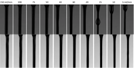
Fig. 3 - The influence of liquid flow rates on the regime flow with an aluminum wire diameter of 1 mm for water (top) and ethanol (bottom) without a countercurrent airflow.
the wires are obtained by 3D printing from the same manu facturer of the packings. Three materials were used during the printing; stainless steel in order to be consistent with the industrial packings, aluminum since for future potential applications, Al is found to be effective in HIDiC columns (in terms of heat transfer), and polyamide (PA12) to reduce the fabrication costs and delays of the printing. For every configu ration, the liquid flowrate varies from 5 to 150 mL/min. These flowrate values are chosen to correspond to the liquid loads used in industrial columns. Nevertheless, in order to convert this indus trial liquid load to a liquid flowrate per wire, it is nec essary to know the wires number per square meter of packing sections, which will depend on the final design of the pack ing. The selected designs have between 26,000 and 155,000 wires per square meter. The range of the used liquid flowrate will be therefore in accordance with the industrial liquid load (between 2 and 200 m3/m2/h). During the experiments, two
liquids were used (demineralized water and ethanol) in order to study the influence of the surface tension and approach the one of the n-heptane/cyclohexane mixture, which is used in the HETP characterization. The effect of the airflow is deter mined using the F-factor that describes the vapor load. This F-factor is defined as the product of the superficial vapor velocity and the square root of the vapor density (Eq. (1)). Throughout the experiments, it increases to 3 Pa05 in agree
ment with the industrial vapor loads. For higher values of F, flooding will appear in the pilot.
(1) As several materials and liquids are used, a contact angle characterization must be performed. The angle is measured via the captive bubble method on the 2 mm wires used for the thickness measurements using three different liquids, (1) water, (2) ethanol, and (3) a mixture ofn-heptane/cyclohexane. In general, a good wetting corresponds to small contact angles (less than 90°). The results show the minor effect of
the surface tension on static contact angles as well as the good wettability of the three materials. Under atmospheric pressure and ambient temperature, the measured contact angles on a polyamide wire for the three mentioned liquids are respec tively 37°, 39°, and 40°. For an aluminum wire, the values of
the contact angles are 38° for water, 40° for ethanol, and 37° for
the binary organic system. However, with stainless steel wires
and under the same working conditions, the resulted contact angles are (1): 33°, (2): 37°, and (3): 40°. All these measurements
are under static conditions, whereas with the operating condi tions, it is the dynamic contact angle that has to be considered. Therefore, these results must be viewed as indicative only.
3.2. Observations and results
Using water as the operated liquid, a stable and total wetting regime is observed, except for small liquid flowrates (below 15 mL/min), where a partial wetting can be noticed with the appearance of a droplet stream (Fig. 3 top). For each case, a meniscus is developed at the injection point followed by a decrease of the liquid film thickness until stabilization. In our case study, only the flow initialization is under investiga tion, since the wires composing the packing have a maximum length of 20 mm before any intersection. For the same con figuration, but using ethanol as the operated liquid, a wetting regime is also observed for low values ofliquid flowrates (Fig. 3 bottom).
As a further explanation, it should be noted that under a liquid load of 5 m3/m2/h, the flow rate per wire is around 3.5
mL/min for the configurations having a minimum number of wires (i.e. 26,000 wires per square meter). A partial wetting is then observed when operating with water, since the flow rate is inferior to 15 mL/min. Yet, this limitation is not applica ble to the ethanol as it was previously stated. In addition, for non-wetting systems, there is indeed a risk of partial wetting under low liquid flow rates, even with a lot of water. Tradi tional packings can experience partial wetting phenomena under the same operating conditions as well.
Furthermore, liquid film thicknesses are measured and a parametric study is proposed to analyze the impact of the injection and wire diameter along with the air and liquid flowrates. This part of the study is realized using deminer alized water. For these measurements, an average thickness is calculated disregarding the meniscus zone, since the stabi lized flow is used to characterize the configuration.
Visually, the liquid flowrate shows an important influence on the flow regime. By measuring the liquid film thickness, this thickness increases with the increase of the liquid flowrate. As shown in Fig. 4a, this increase is split into two zones with a step between them, corresponding to the two regimes observed visually in Fig. 3.
a
b
1
0.8
E
0.9
0.8
E'
0.7
.ê.
<I)0.7
<I)0.6
<I) <I) (1)0.6
(1)o.s
�
0.5
�
0.4
:S0.4
d1n
:SF-factor
�
0.3
2mm
-
�
E
0.3
0Pa0-5 -
1
P
a0·5
-12
0.2
2
.Smm
-
�
0.2
::, ::,2
P
a0•
5
-.
!2"
0.1
LJ
Jmm
-
-
!2"
0.1
3patJ.S
---...J
0
...J0
.L l L .L0
20
40
60
80
100 120 140 160
0
20
40
60
80
100 120 140 160
Liquid flow rate (ml/min)
L/quid flow rate (ml/min}
Fig. 4 - (a) The influence of injection diameter (F = 1 Pa0·5 - d
w = 0.5 mm - water on aluminum) and (b) the influence of
F-factor (din =2 mm - dw = 0.75 mm - water on stainless steel).
a
b
0.8 0.8 Ë 0.7 Ë 0.7 ,§_ ,§_ U) 0.6 U) U) 0.6 q, 0.5 q, i::: i::: 0.5 0.4t
:S 0.4 E 0.3�
0.3 il:: 12 0.2 12 0.2 ::, lmm- ::, Aluminum--3"
0.1 ,t;; 0.1 2mm--_,
PA12 -0 0 0 20 40 60 80 100 120 140 160 0 20 40 60 80 100 120 140 160Llquld flow rate (ml/min) Llquld flow rate (ml/min)
Fig. 5 - (a) The influence of wire diameter (din = 3 mm - F = 0 Pa0·5 - water on aluminum) and (b) the influence of wire
material (dw
=
0.75 mm - F=
0 Pa o.s - d;n =2 mm - water).The use of different injection diameters shows no influ
ence on the average liquid film thickness (Fig. 4a). For high
flowrates, a small increase of the thickness with the injection diameter is detected.
For different configurations of wire and injection diam eters, several F-factors are used, which corresponds to the
industrial rates (0 to 3 Pa05). Fig. 4b shows no influence of
this parameter (from O to 2 Pa05) on the liquid film thickness,
since the low velocities induce a small shear stress on the liq
uid interface. However, at high F-factor (3 Pa05), the liquid film
thickness deviates under low liquid loads. In fact, having an F factor equal to 3 in a distillation column is rarely observed;
usually with an F = 3, we have flooding and unstable condi
tions.
In addition, four different wire diameters were used in order to study their impact on the liquid film thickness. As
illustrated in Fig. Sa, the liquid film thickness increases with
the decrease of the wire diameter.
This thickness rise is partially explained by the neces sity to conserve the size of the crossing surface when the wire diameter decreases. Nevertheless, the evolution of the liquid section with the wire diameter does not show a con servative value or a monotonous growth, which indicates the influence of local forces. The variation of the liquid sec tion leads to a change of the liquid curvature, which induces a different surface tension action. At the same time, the velocity is modified. Thus, the shear stress at the wire sur face and the boundary layer profile are modified too. In
order to clarify this effect, more wire diameters should be involved.
The measurements in Fig. Sb were performed using three
different materials: stainless steel, aluminum, and polyamide in order to study the effect of these materials on the liquid film thickness. The contact angles were measured similarly and for each material; the same behaviors were identified. The comparison between the measured thicknesses shows a liquid increase when passing from the PA12 wire to the metal wire and a low thickness difference between the aluminum and stainless steel wires. These results, both obtained with water and ethanol, are difficult to explain in regard of the contact angle. The use of one static contact angle and not the dynamic one could be a lead, but it is difficult to manage it on wire portions. It can be concluded that the contact angle does not allow the prediction of the liquid behavior. Moreover, the liquid flow on PA12 materials is unfavorable compared to the metal materials given the liquid film thicknesses.
Finally, the comparison between the two used liquids is
presented in Fig. 6. 'I'wo phenomena can be represented. For
small liquid flowrates, a difference appears due to the differ ence in the flow regime for water experiments. An increase of the wetting occurs when using the ethanol, which has a lower surface tension than water. A good wetting is observed for all liquid flowrates, even for the lowest ones. Thus, in the case of ethanol flow, the increase ofliquid film thickness with the liquid flowrate is continuous without any change of the regime. With high flowrates, the same thicknesses are
mea-0.8
E
0.7
.ê.
0.6
0.5
.2
0.4
:SE:
i;::0.3
:'Q0.2
-�
0.1
-.J0
0
wlre d/ameter
0.5 mm
-
0.5 mm
0
.
75mm
-+-
0.75mm
-50
100
lmm
-
1-150
Uquid now rate (ml/min)
200
Fig. 6 - The comparison of liquid film thicknesses on aluminum wires for water (blue) and ethanol (red) (din =2 mm - F = O Pa0·5 -numerous d
w),
sured; the result is in agreement with the contact angles that were similar for the different materials and liquids. There fore, the surface tension has an important role in the liquid flow regime on wires. When the wire is well wetted, the sur face tension has no longer effects, since the same liquid film thickness is detected.
3.3. Comparison with Nusselt mode! (Nusselt, 1916) This model is based on the analytical solution of a station ary flow with a constant thickness (t1) film. The velocity u(r) and the pressure P(r) are considered constant along the wire. The momentum equation along the wire (x direction) is then calculated using this equation:
!
r dr dr !!_(
r
!!_)
u = _ Pl9/1-l (2) Where Pl, µ.1 and g are respectively the density, the dynamic viscosity, and the acceleration of gravity.Eq. (2) can be integrated using the boundary conditions of no slipping on the wire of radius rw (Eq. (3)) and the negligible
value of the tangential stress at the liquid surface (Eq. (4)). (3) (4) The obtained solution is then used for a stationary flow and it is called Nusselt solution.
u (r) = .EH_
[b
+ ti)2ln(!_) -
! (r
2 - r/)]2µ.1 rf 2 (5)
The logarithmic term in the above equation takes into account the curvature effect of the wire.
From Eq. (5), it is possible to defi.ne the linear liquid flow rate (q1 = OJ./2rrprf where Qi is the mass flow rate):
(6)
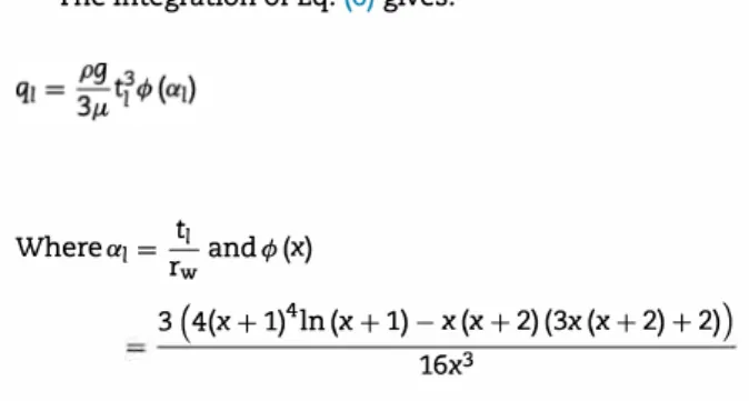
The integration of Eq. (6) gives:
t1
Where a1 = - and <f, (x) rw
3 ( 4(x + 1)4ln (x + 1) - x (x + 2) (3x (x + 2) + 2))
16x3
(7)
q1 is calculated using the relation mentioned above (q1 = OJ/2rrprf) and replaced in Eq. (7) in order to obtain an approx imation of the liquid fi.lm thickness before its destabilization. Duprat (2009) observed that the destabilization length is usu ally greater than 1.5 cm, which is the length of the wires composing the packings. For this study, the destabilization of the liquid flow is then neglected. This is what justifies the comparison of the model with the experimental measure ments and confi.rms the tendencies, even if the results are only approximations.
It is interesting to highlight the fact that the surface tension is not taken into consideration in this model. This assump tion is in agreement with the experimental measurements, since the same thickness was obtained for the different liq uids. However, the viscosity and the density have an influence on the calculated thicknesses. As shown in Fig. 7a, the value ofliquid fi.lm thickness differs between water and ethanol and this was not observed experimentally.
The comparison of the liquid film thickness between the model and the experimental measurements shows similar tendencies concerning the effect of the wire diameter; yet, the magnitudes are not accurate (Fig. 7b). For larger diame ters (2 mm), the values of the theoretical and experimental thicknesses are close. However, for smaller diameters, the the oretical thicknesses deviate from the experimental ones. In fact, the model is derived from a non-deformed liquid film example, which becomes less accurate when the diameter decreases. The change of the regime that took place with water cannot be achieved with this model, which considers a con tinuous liquid fi.lm. Finally, this model can be used to have a rough estimation of the liquid film thickness developed on a wire portion. In this way, it allows the increase of the geometric surface of a new wire based packing to be reckoned.
4.
Liquid flows on packing partsThe influence of wires intersection is investigated in this section. The chosen geometry developed for this study is illus trated in Fig. 8. It corresponds to a part of the packing that will be presented in the second article (part II). These packings are composed of a wire, on which the flow settles. The fi.rst wire is split into three other wires forming the tetrahedron edges. These tetrahedron edges are then added symmetrically in the opposite direction to have a flow coming from the three upper wires and going towards the three others.
The effect of wire length, diameter, and angle along with the effect of air flowrate and liquid type are examined under neath. For all these studies, the packing parts are 3D printed. The fi.rst tests are made on aluminum parts whereas the second ones are made on stainless steel packings. For both materials, the results are the same.
Ê ,ê.
"'
"'
Q)�
-s! :S�
�
.Q'" __, 0.6 0.55 0.5 0.45 0.4 0.35 0.3 0.25 0.2 / / L,.
a
...
.,,..
--
-
...
.,,..
.
--
.,,..
...
__
-/'.,,..
_
_ ,,,.
/ ; ,' / wire diameter -; 0.5mm - -- 0.5mm t, 2mm-·- 2mm-· -0.15 _____J____ ____j_ ---L 0 50 100 150Liquid flow rate (ml/min)
b
0.8 Ê 0.1 ,ê."'
0.6"'
Q) 0.5�
-s! 0.4 :S�
0.3�
0.2 0.5mm -.Q'" 0.1 Jmm- ·-__, 2mm - -0 200 0 20 40 60 80 100 120 140 160Liqwd flow rate (ml/min)
Fig. 7 - (a) The comparison of liquid film thicknesses from the models for water (blue) and ethanol (red) and (b) the
comparison of the calculated thicknesses (dashed lines) with the experimental measurements (dots with lines) (d;n = 3 mm - F = O Pa0·5 - aluminum).
Fig. 8 - An illustration of a pan of the packing used in the test section in order to understand the liquid flow on the intersections.
4.1. Effect of wire length
In a first time, the effect of the wire length (i.e. the length of tetrahedron edges) is studied. As illustrated in Fig. 9, the liquid flow was englobing ail the structure in the case of a short length. This result is found in two cases: (i) for the 4 mm wire length under ail liquid flowrates and (ii) for the 7 mm wire length under high flowrates only. However, for higher lengths (10 and 13 mm), the liquid flow was more or less splitting on the edges depending on the conditions.
These first visualizations proved that it is difficult to obtain a good repartition of the liquid between three different wires of the structure. Fig. 9a (example of the 7 mm wire length) shows the development of a membrane which is a liquid film formed between the two edges and the third dry or wet wire
depending on the conditions. Moreover, Fig. 9a (example of the 13 mm wire length) shows that the liquid is capable offlowing on only one or two wires of the tetrahedrons.
In order to improve the flow repartition on the wires, different solutions were envisaged. Firstly, the shape of the tetrahedron edges is modified a little. The idea behind this modification is to smooth the edges shape by using a spline function at the intersection. Two shapes are therefore tested. They showed an improvement in the flow separation, since less membrane-like flows were observed. However, the liquid was always flowing on two edges (Fig. 9b). This improvement of the geometry is then added to the next tests.
4.2. Effect of wire diameter
The study of the flow on simple wires highlighted the influence of the diameter. Thus, this parameter has to be investigated for the packing parts too.
For this study, the packing parts are fabricated in PA12 due to shorter 3D printing delays and better shape of the spline. This change in the material does not seem problematic. In fact, a performance decrease is observed with the PA12 pack ings (particularly when measuring the liquid film thickness). Therefore, using stainless steel packings, better results must be found.
Eleven samples were tested with different wire diameters: 0.83, 0.94, 1.03, 1.14, 1.26, 1.37, 1.44, 1.57, 1.69, 1.79, and 1.85 mm. The results show that the flow regimes primarily depend on the wire diameter and liquid flowrates.
Fig. 10 displays a mapping of the different liquid flow regimes observed on the packing parts for pure ethanol. Three main regimes are identified (capillary, inertial, and wetting) with two other transitionary zones.
The inertial flow regime is observed under high flowrates with packings having small wire diameters. Due to the high flowrate (high velocity), the wires are not able to perturb the trajectory because of their small diameters. The liquid does not perfectly follow the wires and at least one of them is not wetted. The regime is then controlled by the inertia of the liquid flow and the surface tension is considered negligible.
The capillary flow regime is found under low liquid flowrates and with small wire diameters. A droplet stream and a flow on only one wire are detected. In this case, the sur face tension is predominant. This regime is then piloted by the capillarity due to the high influence of the surface tension.
a
b
4mm 7mm 10mm 13 mm spline shape
Fig. 9 - (a) The influence of the wire length on the liquid flow on packing parts (Water - Aluminum - No airflow - dw = 1 mm) and (b) the effect of spline shape on liquid flow Water - Aluminum - No airflow - dw = 1 mm - lw = 10 mm).
2
•••••••
1.8
•
••• • • •
•
•
,§_
1.6
•
•
•• • • •
•• • • •
Weitlo,g_•
•
•
•
••
• •
•
•
•
!lJ1.4
E:
••
•
• •
• •
•
•
�
1.2
•
••
• •
•
•
!lJ•
••
•
•
•
•
•
•
�
ln�rtin1
•
•
••
• •
•
•
•
�PM",; • ••
•
•
0.8
•••
•
•
•
0
20
40 60
80
100 120 140 160
Liquid flowrate (ml/min)
surface tension > lnertfa • lnettfa > surface tension • Fig. 10 - A mapping of the liquid flow regimes on the packing part for ethanol.
The two mentioned regimes illustrate the competition between the surface tension and the inertia on the liquid flow. However, for the third regime, a balance between these two actions is achieved, which leads to the wetting of the intern part and the repartition of the liquid flowrate. This regime is favored in the case of wire-based packings; it is called wetting. The mapping in Fig. 10 illustrates the transitions between the predominant forces and demonstrates the necessity to have wires of a minimal size to allow a good wetting and flow repartition.
Finally, from the three main flow regimes, intermediary zones are identified. The first zone (purple) characterizes the action of the surface tension that is superior to the inertia. The structure is properly wetted, but the liquid flow is not perfectly divided due to the influence of gravity. On the opposite, when the inertia is dominant, the second zone (orange) appears. The liquid is flowing on two wires with generally a membrane, whereas the third one is always wetted. These transitionary regimes are acceptable too.
4.3. Effect of air Jlowrate
Concerning the studies done on simple wires, visualizations are made for different air flowrates. For the packing part of 1.69 mm wire diameter, three F-factors (1, 2, and 3 Pa05) are
a pp lied. The addition of airflow has no visible influence on the transition of liquid flow. It can be explained again by the low airflow velocity, which does not induce enough shear stress to truly affect the liquid.
4.4. Effect of liquid type and Jlowrate
To pursue this study, the effect of the liquid flowrate and type is explored. Three different liquids are used to examine the impact of their physical properties such as surface tension and density .
Severa! observations are conducted using water with pack ing parts having different diameters: 0.83, 1.37, and 1.85 mm. The wetting regime is never obtained. Depending on the wire diameter and liquid flowrate, the inertia or capillarity regimes occur.
1\vo other liquids are tested as well: pure ethanol and a 50-50 ethanol-water solution. The same behaviors are observed for bath systems. Nevertheless, for the 50-50 solu tion, the wetting regime is only noticeable for wire diameters greater than 1.5 mm, while for pure ethanol it is for a diameter ofl.1 mm.
As mentioned in the previous section, the different flow regimes are directed by the competition of the surface tension and the inertia. In order to describe properly the regime transi tions, two dimensionless number are used (Eq. (8)). The Weber number is proposed to characterize the transition. At the same time, two characteristic sizes can also affect the flow; they are the wire diameter (dw) and the capillary length : le = �- The
ratio of dw to le gives the dimensionless diameter. y2
We = !!____J_ andd"
rd!
(8)The mapping in Fig. 11 displays the required balance between the inertia and the surface tension in order to have the wetting regime. The latter is attained under two condi tions: a weber number around 1 and a dimensionless diameter greater than 1.3. The second condition corresponds to the pre ponderant action of gravity over capillarity. When the ratio dwl1c increases, the influence of surface tension decreases. This explains the wide range of Weber number for which wet ting can be obtained.
4.5. Effect of wire angle
In order to investigate the impact of the wire angle, several packing parts of 1.7 mm wire diameter are designed with different angle values: 20-25-30-35-40-45-55-65°. For this
study, the liquid used was ethanol, which induces a d* of 2 to favor the wetting regime.
As shown in Fig. 12a, three behaviors were examined. For high angle values and under high flowrates (greater than 50 ml/min), a liquid detachment appears and the flow does not
1000 100 10 O.J 0.lS J.S J.lS 2 ;us
..
0.1 Capîlla,:îty • 0.01 o.s 0.lS J.2S 1.S J.lS 2 :us 1.lS d"' tthallOI 50/50 wat&- d"' capillarity surfaœ tension > lnertia-lnertla > surff1œ tension
-• ■ •
• ■
• ■ • • ■
• ■
Fig. 11 - A mapping of the liquid flow regimes on the packing part, for the 50/50 solution (left) and for ethanol, water and 50/50 (right).
In the second mapping, the circles are used for the ethanol, the squares represent the 50-50 ethanol water solution, and the triangles symbolize the water. The colors are used to identify the different regimes (blue for capillarity, green for inertia, red for wetting, purple and orange for the two intermediary zones).
a
b
65•
•
• •
• • ■ ■ ■ ■ 60 55•
•
• •
• • ■ ■ ■ ■�
50 '- 45•
•
• •
• ••
■ ■ ■�
î
40·--
• •-•-• ■ ■ 35.
•
-
•
.
•
-
• •
-
•
-30•
..
• •
• • •
• ■ ■ 25 .,_____._,._.,______,.,_...,. ____,.,_
____
_
20·
u..ul__·
__,_·
•-•
.L·
L.Ll,J._· .
_._•
..u..u..1 0.01 0.1 1 10 100 We -■-
-·
■Fig. 12 - (a) The impact of the wire angle (left: 20° -> subsume, center: 40° -> wetting, right: 55° -> liquid detachment) and (b)
the mapping of the influence of the wire angle.
follow the wires. This behavior is detected for angles greater than 40°. However, for small angles (below 30°), the liquid flow
covers all the structure (as observed for small wire lengths). This can be observed for the packing parts of 20° wire angle
under all flowrates and 25° wire angle under high flowrates
(greater than 75 ml/min) after membrane formation. Finally, for any angle between 30° and 40°, the behavior
is the same as the one described during the analysis of the impact of the wire diameter. A mapping is proposed to present these different regimes in Fig. 12b.
5. Conclusion
In conclusion, the performance of a separation column can be described by adopting an innovative well-structured packing. Our packing is composed by a tangle of wires and fabricated using 3D printing. The underlying innovative ide a of the wire is its higher interfacial surface compared to a plate based pack ing for a same geometrical surface.
In a first time, a study on the liquid flow on simple wires for different materials, wire diameters, and flow rates were
conducted. The results highlighted the great influence of the diameter on the liquid film thickness. However, the impact of the printed material, contact angles, and surface roughness was difficult to determine. Moreover, the liquid film thickness developed on the wires was compared to the theoretical thick ness calculated by the Nusselt approach. This model gives a primary idea on the increases in the surface exchange that can be caused by the presence of the liquid on the wires, depending on the operating conditions.
In a second time, a study on the liquid flow on packing parts was performed. The wettability of the liquid on the wire will depend once again on several parameters, such as the diameter of the wire. In order to promote a good wettability of the packing, it is necessary to design a structure with proper values of wire diameter, wire length, and contact angles for the liquid to be appropriately split on the edges.
Finally, a mapping that predicts the liquid flow regimes was deduced. It represents the dimensionless Weber number versus the ratio of the wire diameter to the capillary length. This mapping displays the mandatory balance between both surface tension and inertia in order to obtain the targeted
wet-ting regime. It also proves the necessity to create a packing design having a tangle of structured wires with a minimal diameter size to achieve a good wetting and a good flow repar tition.
Conflict of interest None.
Acknowledgement
The authors gratefully acknowledge the financial support of the ADEME(French Environment & Energy Management Agency) and the partners of the project ARKEMA andLABBE. References
Carroll, B., 1976. The accurate measurement of contact angle, phase contact areas, drop volume, and Laplace excess pressure in drop-on-fiber systems. J. Colloid Interface Sei. Carroll, B.J., 1981. The kinetics of solubilization of non polar oils
by nonionic surfactant solutions.]. Colloid Interface Sei.
Carroll, B., 1986. Equilibrium conformations of liquid drops on thin cylinders under forces of capillarity. A theory for the roll-up process. Langmuir 2, 248-250.
Duprat, C., 2009. Instabilités d'un film liquide en écoulement sur une fibre verticale. Thèse de doctorat - Université Pierre et Marie Curie Paris VI.
Gilet, T., Terwagne, D., Vandewalle, N., 2009. Digital microfluidics on a wire. Appl. Phys. Lett. 95, 14-106.
Gilet, T., Terwagne, D., Vandewalle, N., 2010. Droplets sliding on fibres. Eur. Phys. J. E 31, 253-262.
Lorenceau, É., Clanet, C., Quéré, D., 2004. Capturing drops with a thin fi ber. J. Colloid Interface Sei. 279, 192-197.
McHale, G., Newton, M., 2002. Global geometry and the
equilibrium shapes of liquid drops on fi.bers. Colloids Surf. A: Physicochem. Eng. Asp. 206, 79-86.
McHale, G., Newton, M., Carroll, B., 2001. The shape and stability of small liquid drops on fi.bers. Oil Gas Sei. Technol.
Mullins, B.J., Agranovski, I.E., Braddock, R.D., Ho, C.M., 2004a. Effect of fiber orientation on fi ber wetting processes. J. Colloid Interface Sei. 269, 449--458.
Mullins, B.J., Braddock, R.D., Agranovski, I.E., 2004b. Particle capture processes and evaporation on a microscopie scale in wet filters. ]. Colloid Interface Sei. 279, 213-227.
Nusselt, W., 1916. Die Oberfüichenkondensation des Wasserdampfes. VDI Zeitschrift 60.