To link to this article
: DOI: 10.1016/j.surfcoat.2011.09.056
URL:
http://dx.doi.org/10.1016/j.surfcoat.2011.09.056
This is an author-deposited version published in:
http://oatao.univ-toulouse.fr/
Eprints ID: 5626
To cite this version:
Balcaen, Yannick and Radutoiu, Nicoleta and Alexis, Joël and Béguin,
Jean-Denis and Lacroix, Loïc and Samélor, Diane and Vahlas, Constantin
Mechanical and barrier properties of MOCVD processed alumina
coatings on Ti6Al4V titanium alloy. (2011) Surface and Coatings
Technology, vol. 206 (n° 7). pp. 1684-1690. ISSN 0257-8972
O
pen
A
rchive
T
oulouse
A
rchive
O
uverte (
OATAO
)
OATAO is an open access repository that collects the work of Toulouse researchers
and makes it freely available over the web where possible.
Any correspondence concerning this service should be sent to the repository
administrator:
[email protected]
Mechanical and barrier properties of MOCVD processed alumina coatings on Ti6Al4V
titanium alloy
Y. Balcaen
a, N. Radutoiu
a, J. Alexis
a,⁎
, J.-D. Beguin
a, L. Lacroix
a, D. Samélor
b, C. Vahlas
baUniversité de Toulouse, LGP-ENIT/INPT, 47 avenue d'Azereix, BP 1629, 65016 Tarbes, France bUniversité de Toulouse, CIRIMAT/INPT, 4 allée Emile Monso BP 44362, 31030 Toulouse cedex 4, France
a b s t r a c t
Keywords: CVD Alumina Mechanical properties AdhesionHot salt corrosion
This study focuses on the implementation of different aluminum oxide coatings processed by metal-organic chemical vapor deposition from aluminum tri-isopropoxide on commercial Ti6Al4V titanium alloy to im-prove its high temperature corrosion resistance. Films grown at 350 °C and at 480 °C are amorphous and cor-respond to formulas AlOOH, and Al2O3, respectively. Those deposited at 700 °C are composed of γ-Al2O3
nanocrystals dispersed in a matrix of amorphous alumina. Their mechanical properties and adhesion to the substrates were investigated by indentation, scratch and micro tensile tests. Hardness and rigidity of the films increase with increasing deposition temperature. The hardness of the coatings prepared at 350 °C and 480 °C is 5.8 ± 0.7 GPa and 10.8 ± 0.8 GPa respectively. Their Young's modulus is 92 ± 8 GPa (350 °C) and 155 ± 6 GPa (480 °C). Scratch tests cause adhesive failures of the films grown at 350 °C and 480 °C whereas cohesive failure is observed for the nanocrystalline one, grown at 700 °C. Micro tensile tests show a more pro-gressive cracking of the latter films than on the amorphous ones. The films allow maintaining good mechan-ical properties after corrosion with NaCl deposit during 100 h at 450 °C. After corrosion test only the film deposited at 700 °C yields an elongation at break comparable to that of the as processed samples without corrosion. The as established processing–structure–properties relation paves the way to engineer MOCVD aluminum oxide complex coatings which meet the specifications of the high temperature corrosion protec-tion of titanium alloys with regard to the targeted applicaprotec-tions.
1. Introduction
Lightweight titanium alloys find nowadays potential use in numerous domains involving advanced materials for jet engine, other aerospace applications, desalination plants, orthopedic or den-tal implants and sporting goods. However, in addition to the elevated cost of such alloys, their implementation is hindered by their limited resistance to salt corrosion at high temperatures, when operation in such environments is part of the specifications of the material. It has been difficult until now to protect titanium alloys with coatings showing satisfactory behavior in terms of adhesion and substrate protection against stress corrosion cracking. These situations concern, for example the spinning centrifugal turboshaft engine, manufactured in Ti6Al4V titanium based commercial alloy. This part of the engine is very susceptible to oxidation and hard to protect. It is indeed generally not enough protected. For this reason, it suffers from a fairly high attri-tion rate and needs detailed periodic inspecattri-tions. The presence of salt combined with strong mechanical stress generates hot salt stress corro-sion phenomena (HSSC), which can lead titanium alloys to an untimely
failure. It is generally accepted that hydrogen is the major cause of embrittlement through a mechanism involving four steps: substrate corrosion, hydrogen generation, substrate embrittlement and crack initiation and propagation. Application of protective coatings on titanium alloys may improve their corrosion resistance and subsequently maintain their mechanical properties in corrosive, high temperature environment. Al2O3has received recent attention due to its surface and barrier
proper-ties, allowing for its use as catalytic support and as protective coating with enhanced mechanical properties and chemical durability. In addition to its numerous allotropic modifications and to the subsequent large spec-trum of structure–properties relationships, Al2O3 can be processed in
the amorphous state and remain amorphous in a large temperature range. Metalorganic Chemical Vapor Deposition (MOCVD) of alumina has been reported many times in the literature. However, only a few works explicitly deal with the deposition of amorphous alumina films[1]. Significant work has been provided by the authors in the recent years in this field. Especially, the relation between the operating condi-tions of Metalorganic Chemical Vapor Deposition (MOCVD) and the char-acteristics of the obtained amorphous Al2O3 coatings, including the
modeling of the process considering appropriate chemical kinetic schemes[1–6]was discussed. The rationale of these investigations is based on two pillars: the first concerns the moderate deposition temper-ature which is compatible with the thermal loads the substrate can
⁎ Corresponding author. Tel.: +33 562442723; fax: +33 562442708. E-mail address:[email protected](J. Alexis).
tolerate without modification of its microstructure and, consequently of its properties and performance. The second is based on the excellent barrier properties of the amorphous alumina films allowing for efficient protection of easily oxidized light weight alloys such as the titanium (and possibly magnesium) based ones. Indeed, preliminary investigation of combined thermal, mechanical and chemical stresses applied on phys-ical vapor deposited (PVD) SiC and SixNy, and of MOCVD amorphous
Al2O3 coatings on Ti6242 alloys, revealed that the first two suffered
from severe damage resulting in less efficient protection of the alloy, while only the latter maintained its integrity (except minor damage in the form of localized small pits and subsequent local spallation of the films)[7,8]. It was concluded that understanding and improving the mechanical compatibility was the key factor for the Al2O3/Ti system to
corrosion protection.
Based on the above, the objective of this study is to make further progress in the establishment of the correlation between the charac-teristics of the coatings and their capacity to protect the Ti6Al4V alloy in conditions that are at least as severe as the ones prevailing during its targeted operation. The work consists of depositing on Ti6Al4V aluminum oxide films of three different microstructures, namely amorphous aluminum oxyhydroxide AlOOH, amorphous aluminum oxide Al2O3and Al2O3oxide composed of amorphous and
nanocrys-talline domains. The three coatings are processed under different conditions and are expected to provide coating/substrate couples with different combined thermal, mechanical and chemical behaviors with regard to preestablished specifications. In this way, it is expected to reveal the mechanical behavior of the metal/oxide interface per se, thus defining in a subsequent step appropriate combinations of surface functionalization — film characteristics leading to an integrated surface engineering of the Ti6Al4V alloy.
In the following, the processing parameters and mechanical tests carried out will be introduced first. Then, the intrinsic mechanical properties and the adhesion of coatings will be presented and discussed with regard to their deposition temperature, before providing concluding remarks.
2. Material and methods 2.1. Material
MOCVD of alumina coatings was performed in a tubular, horizon-tal hot-wall reactor at 666 Pa and at temperatures between 350 °C and 700 °C. Aluminum triisopropoxide (ATI) was thermoregulated in a bubbler at 100 °C and was carried to the deposition zone, with 99.9992% pure nitrogen as carrier gas.Table 1resumes the processing conditions. It is recalled that under such conditions, the composition, microstructure and crystallinity of the alumina films strongly depend on the deposition temperature. These grown in the range 350 °C– 415 °C are amorphous and partially hydroxylated AlO1 + x(OH)1 − 2x
with x varying from 0 (AlOOH) at 350 °C to 0.5 (Al2O3) at 415 °C.
Those processed between 415 °C and 650 °C are composed of amor-phous Al2O3 and those processed around 700 °C contains γ-Al2O3
nanocrystals distributed in an amorphous Al2O3 matrix. The film
thickness is approximately 1 μm.
2.2. Methods
A detailed description of the compositional and structural analysis of the as deposited films is presented in[5]. A nanoindentor XP from MTS was used with a Dynamic Contact Module (DCM) to determine the hardness. On each coating, a matrix of 20 measurements in the Continuous Stiffness mode was carried out with a Berkovich indenter by fixing a maximum in-depth displacement of 300 nm. In order to overcome the influence of the substrate, taking into account the roughness, the interval for calculating the properties of the deposits varies between 30 and 100 nm. The Young's modulus of the coatings was calculated starting from the contact stiffness (Eq.(1))[9].
Se¼ 2 ffiffiffi π p Er ffiffiffiffiffiffiffiffiffiffiffiffi A hð Þc q : ð1Þ
Seis the stiffness of contact determined in the higher part of the
unloading curve, A(hc) the contact area as a function of the
indenta-tion depth. Eris the reduced modulus of the system holding account
of the Young's moduli and the Poisson's ratios of indentor (Ei, vi)
and of the sample (Ee, ve) (Eq. (2)). To calculate Ee, the Poisson's
ratio vewas set to 0.2.
1 Er¼ 1−ν2i Ei þ 1−ν2e Ee : ð2Þ
The quantitative determination of the adhesive strength is difficult or even impossible due to the adherence and thickness of the coatings
[10]. Moreover, there is a multitude of adherence tests, more or less simple, more or less qualitative. More than 355 different tests have been compiled by Mittal[11]. The choice of a test depends on its appli-cation. It must be as simple as possible to implement and pertinent; its parameters must be known and controlled. Taking into account these criteria, micro tensile tests and micro scratch tests were used for the determination of the adhesion of the coatings. Micro tensile tests were performed with a KUSTOM TS 250 designed to be used in a JEOL JSM6400 scanning electron microscope. The setup allows 250 daN and 4 mm maximum load and elongation of the sample, respectively. 0.6 mm-thick samples with useful area of 7 × 2 mm2were elongated
at a 0.6 mm/min rate. According to Ohmura and Matsuoka[12], the more important the crack density is at the end of the test, the higher is the adherence. Based on this fragile behavior, the adhesion of the coatings can be estimated using the model suggested by Agrawal and Raj[13]which allows calculating the value of the critical shear stress, τ, before the delamination of the coating (Eq.(3)).
τ¼πeλfσ ð3Þ efis the film thickness and λ is the wavelength of the sinus function
defining the shear force at the substrate–deposit interface. λ=2λ0
corresponds to the distance between two cracks when the sample sur-face is cracks saturated, σ is the maximum normal stress supported by the film. According to Chen et al.[14,15]the maximum normal effective stress in the film, considering the internal stresses, is:
σ¼ σaþ σr: ð4Þ σais the stress when the first crack appears and σrthe residual stress of the film. Considering that the film is fragile, it is assumed that σa+ Efεf.
Thus τ equals: τ¼2πef :λ0 : Efεfþ σr " # : ð5Þ
Scratch adhesion testing was carried out using a CSEM® commer-cial microscratch instrument. A Rockwell C diamond indenter with a
Table 1
Processing conditions for the growth of Al2O3coatings.
Growth temperature (°C) 350–700
Pressure (Pa) 666
Carrier gas flow rate (N2, sccm) 20
Dilution gas flow rate (N2, sccm) 632
Total gas flow rate (sccm) 652
ATI bubbler temperature ATI (°C) 100
ATI molar fraction (10− 3) 2.35
Deposition time (min) 5–60
200 μm radius was used at a scratch speed of 10 mm/min. During each scratch test, the normal load was continuously increased from 30 mN at a loading rate of 100 N/min until severe interfacial failure occurred. The critical normal load, Lc, corresponding to the initiation
of the interfacial failure, was detected by a sudden increase in acous-tic emission and was confirmed by observation with a scanning elec-tron microscope (SEM-FEG JEOL 7000F). SEM observations and Energy Dispersive X-ray analysis (SDD BRUKER — 129 eV) allowed to determine the type of debonding (adhesive or cohesive). Hot salt corrosion tests were performed on uncoated and coated samples after deposition of NaCl. This deposition was performed by applying a calibrated droplet of saline solution on the surface of the sample. The NaCl solution was prepared with natural sea salt and deionized water. Salt crystallization on the tested surface was obtained by maintaining the sample in an oven for 5 min at 115 °C. This procedure allows obtaining reproducible application of the salt. The deposited mass of NaCl was 120 μg with a local salt concentration of 3 mg/cm2. This value is 10 times greater than the salt concentration
present in engines exposed to severe service conditions[16]. After the salt deposition, the sample was introduced in a furnace at 450 °C during 100 h. This temperature was determined based on the maximum operating temperature of the targeted application. After the experiment, the degradation of the mechanical properties (maxi-mum strength, yield strength, ductility) of the tensile samples was evaluated. The results were combined with postmortem fracto-graphic studies, and were compared with the intrinsic properties of the coatings and with their adhesion to the substrate.
3. Results and discussion
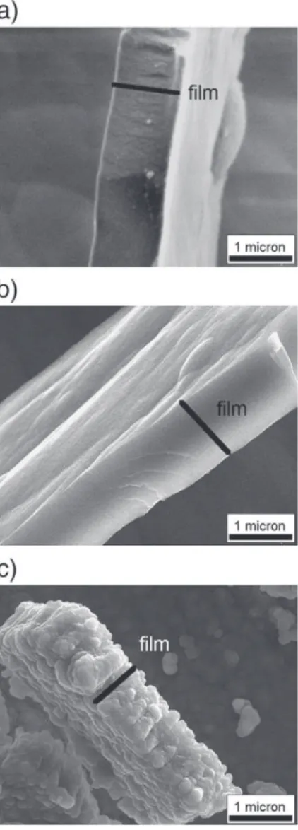
The microstructure of the coatings is illustrated by the cross-sectional scanning electron micrographs ofFig. 1. The coatings depos-ited at 350 °C and 480 °C are compact and free of porosity and grain boundaries. This microstructure is significantly different from that of the coating prepared at 700 °C, which is composed of columnar grains, oriented perpendicularly to the substrate surface. Fig. 2
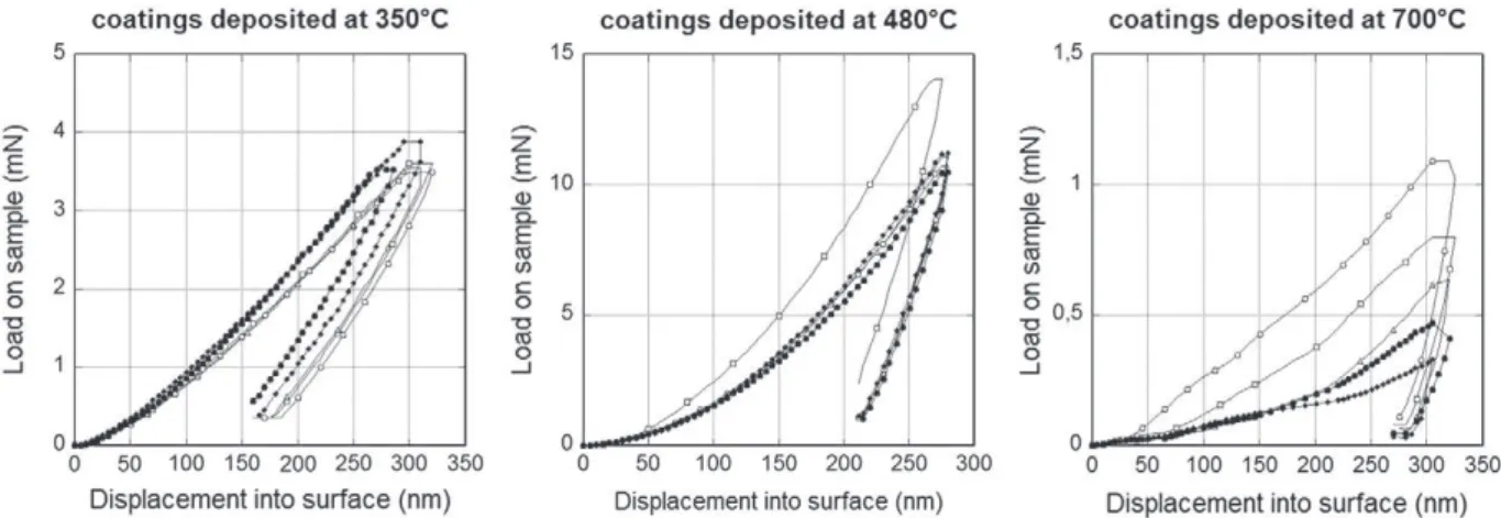
presents the loading and unloading curves of nanoindentation tests. In order to reach the predetermined depth of 300 nm, the applied load varied with the nature of the coating: it was equal to 3.5 mN, 11 mN and 1 mN for the coatings deposited at 350 °C, 480 °C and 700 °C, respectively. There is a clear distinction between the low temperature processed samples and the one processed at 700 °C. The former present better mechanical properties when the latter seems to present lower rigidity and hardness. Tests performed on the coatings deposited at 350 °C and at 480 °C are reproducible in contrast with those performed on coatings deposited at 700 °C. More-over, the loading–unloading curves of the coatings processed at 700 °C are not so reproducible and present numerous inflection points induced by the limited cohesion of the coating and its rough-ness. Thus, no quantitative values of mechanical properties are given for the coating processed at 700 °C.
The ratio of the elementary work values of the elastic and the total deformation during indentation was estimated for the coatings elab-orated at 350 °C and 480 °C. Both energies were calculated from the areas under the load vs. displacement curves (Eq.(6)).
Wð ÞJ ¼ dð Þm× Fð ÞN: ð6Þ
Table 2resumes the calculated areas for the two coatings. Calcu-lated values of hardness and Young's modulus are also reported in this table. It appears that the ratio of the elastic energy over the total energy decreases with increasing the deposition temperature. The values of hardness and rigidity determined by the dynamic nanoindentation tests are well below those given for the bulk alumi-na. This difference may be attributed either to the nanoindentation technique used, or to the influence of the substrate, or to the structure
of the coatings. For this reason, nanoindentation tests were also performed on commercial bulk alumina and on the same coatings deposited on silicon (Fig. 3). The hardness and Young's modulus obtained by nanoindentation on bulk samples are consistent with the results given in literature[17]. The hardness and the rigidity of 92% and 96% pure alpha alumina are equal to H92%= 20 ± 6 GPa,
E92%= 320 ± 50 GPa and H96%= 33 ± 3 GPa, E96%= 423 ± 37 GPa,
respectively. Whatever the nature of the substrate, the hardness and rigidity of the films increased with increasing the deposition temper-ature up to 480 °C. In addition, the hardness and Young's modulus of coatings prepared on silicon substrate confirm the values obtained for the coatings on titanium substrate. Therefore, the nanoindentation technique and the selected test parameters are relevant and the low values obtained for the coatings compared to bulk alpha alumina are attributed to differences of the microstructure of the samples. Depending on the deposition temperature, the increased hardness and rigidity seem to correspond mainly to an increase in the purity of the amorphous alumina deposits. Haanappel et al. also showed that the hardness of alumina coatings prepared by Low Pressure MOCVD and Atmospheric pressure MOCVD increases when the deposition temperature increases from 250 °C to 450 °C[18]. They attribute this increase to the disappearance of the amount of the OH group and in particular to the decrease of boehmite (AlO(OH)).
Insight in the intrinsic properties of the coatings allows determining their adhesion to the substrate.
Fig. 1. Cross-sectional scanning electron micrographs of the coatings processed at 350 °C (a), 480 °C (b) and 700 °C (c).
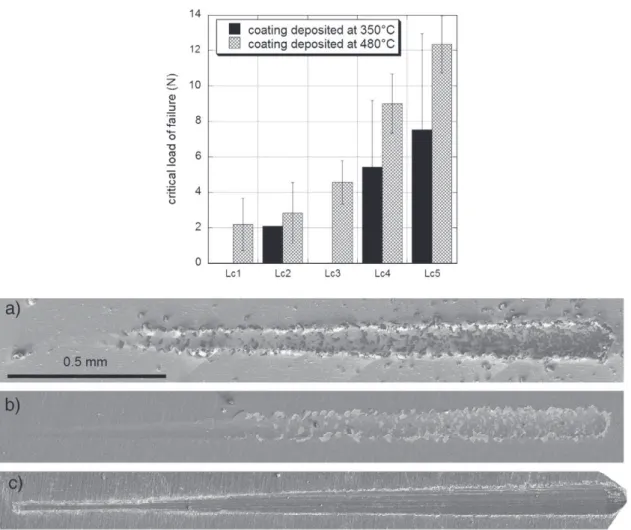
Fig. 4presents the measured critical load of failure (Lci) of the
coatings elaborated at 350 °C and at 480 °C and SEM micrographs of scratches on coatings elaborated at 350 °C (Fig. 4a), 480 °C (Fig. 4b) and 700 °C (Fig. 4c). Such observations allow determining the type of failure of these coatings. Coatings prepared at 350 °C and at 480 °C present a typical mechanical behavior of a hard and brittle ceramic coating film deposited on soft metallic substrate. For each type of damage observed, a critical load of adhesion (Lci) is defined.
Lateral cracking (Lc1) appears at low load, followed by side (Lc2) and
frontal cracks (Lc3). Then fragmentation of the coating (Lc4) and finally
important spallation (Lc5) occur. Regardless of the type of damage Lci
is higher for coatings processed at 480 °C, resulting in a better adhesion of these coatings than that of coatings processed at 350 °C (Fig. 4). This is particularly obvious for heavy load, when spallation appears. The film deposited at 700 °C presents a different mechanical behavior from the other two: it gets damaged already after the pre-scan pass (a load of 0.03 N). Optical microscopy and SEM reveal the wrenched material with small debris.
The above results reveal two scratch behaviors. The films prepared at 350 °C and at 480 °C present adhesive rupture at the interface without plastic deformation (Fig. 4a and b). The fracture behavior of the coating is clearly weak, with clear fracture patterns by cleavage (Fig. 1). The following scenario of failure is proposed to explain this finding. During the pass of the indenter, the coating located forward undergoes compression when the one located backward undergoes tension. The break presents as a crack crossing the coating to the sub-strate, perpendicular to the surface. When compression exceeds a critical value, the coating forms a “blister” forward and on the sides of the scratch. The stress becoming too high, the coating is broken in its entire thickness. Spallations escape or remain trapped under the indenter. Then, the main failure mode in the scratch testing of hard coatings processed at 350 °C or 480 °C is mainly buckling and wedge spallation.
The coating obtained at 700 °C (Fig. 4c) presents a very different scratch behavior from the other two. Unlike the other two, it cracks dur-ing the nanoindentation test, makdur-ing it almost impossible to measure its mechanical properties. During the scratch tests it gets damaged with the pre scan passes (0.03 N load). This illustrates perfectly the
Fig. 2. Loading and unloading curves of nanoindentation tests performed on coatings for different deposition temperatures.
Table 2
Mechanical properties of the coatings as a function of the deposition temperature.
Deposition temperature (°C) 350 480
Total energy (pJ) 451 991
Elastic energy (pJ) 265 337
Plastic energy (pJ) 185 654
Ratio elastic energy/total energy 0.59 0.34
Young's modulus (GPa) 92 ± 8 155 ± 6
Hardness (GPa) 5.8 ± 0.7 10.8 ± 0.8 Fig. 3. Young's modulus (a) and hardness (b) of the coatings processed on Si and on
low cohesion of the film. In addition, its nodular structure contrasts sharply with that of others. However, a thin coating remains adherent to the substrate, even after the most severe scratching. During the scratch test, the deformation is mainly plastic deformation for the soft coating processed at 700 °C. No buckling failure mode is observed. In this case, the scratch test is not well suited to measure the adhesion and simply reveals that the interfacial shear strength is lower than the shear strength of the coating elaborated at 700 °C. The difference in scratch behavior depending on the temperature development can be explained by the intrinsic properties of the coatings and substrates. Coatings were classified according to the classification of Bull[19]
(Fig. 5), i.e. the substrate hardness vs coatings hardness map.
The adhesion of the coatings was also estimated by micro tensile tests. The shear stress at the interface was calculated and presented inTable 3by applying the formula of Agrawal and Raj (Eq.(3)). The distance between cracks was determined far away from the fracture zone by SEM after testing.Table 3presents the results of shear stress evolution as a function of deposition temperature. The shear stress decreases with temperature development. This test confirms the pre-vious results. The coating prepared at 350 °C seems more adherent than the coating prepared at 480 °C. The low shear stress determined for the coating prepared at 700 °C does not represent a value of adhe-sion but its cohesive strength as shown by SEM micrographs of the cracking pattern (Fig. 6). Energy Dispersive spectrometry X-ray anal-ysis confirmed the presence of oxygen and aluminum on the coated tensile specimen at 700 °C after rupture and not on the others. The failure of coatings prepared at 350 °C and 480 °C is adhesive whereas the rupture of the coating prepared at 700 °C is cohesive. To corrobo-rate this, the percentage of coating flaking on the substcorrobo-rate was deter-mined by image analysis with the software AREAS Microvision from observations by scanning electron microscopy. The surface flaking
Fig. 4. Values of critical loads of failure LCiof coatings processed at 350 °C and at 480 °C. LCifor coatings processed at 700 °C is near zero. SEM observations of the scratches made on
coatings elaborated at (a) 350 °C, (b) 480 °C and (c) 700 °C.
Fig. 5. Substrate hardness versus coatings hardness map, delimiting areas within which prevails particular failure mode of the coating revealed by the Bull scratch adhesion test.
Table 3
Evolution of the shear stress at the interface as a function of the deposition temperature.
Deposition temperature (°C)
εf(%) σR(MPa) σe(MPa) δ(μm) λ(μm) τ(MPa)
350 2.36 − 69.5 1075 700 3.70 1249
represents 17%, 55% and 0% respectively for deposits prepared at 350 °C, 480 °C and 700 °C.
Table 4shows the influence of salt corrosion at high temperature on the mechanical properties of coated and uncoated Ti6Al4V alloy. As seen before, the saline corrosion test consists in the exposure of the specimen to salt attack during 100 h at 450 °C. First the influence of oxidation at 450 °C during 100 h was studied. No influence on the ultimate strength or on the ductility was observed. However, the bare Ti6Al4V alloy reveals, after saline corrosion test, a decrease of both the ultimate strength and the ductility revealing the well-known susceptibility of the Ti6Al4V alloy regarding to the salt attack. On the contrary, the yield strength of the coated specimens after is similar to that of the bare specimens before the saline corrosion test. The coatings can thus preserve the good mechanical properties of the Ti6Al4V alloy even after salt attack. However, only the coating prepared at 700 °C yields an elongation at break, after corrosion test, comparable to that of the specimen before the corrosion test. The Ti6Al4V alloy protected by the two other coatings exhibits a fall of ductility. This ductility is indeed 4.9% and 3.2% for the coating obtained at 350 and 480 °C respectively, instead of 11.1% for the bare Ti6Al4V alloy before the corrosion test.
Vickers hardness tests were carried out on cross-sectional areas of the shoulder for gripping of the tensile specimens to verify if the me-chanical properties of the Ti6Al4V recorded during tensile tests are induced by hot corrosion tests or by microstructure changes induced by deposition heating at 350 °C, 480 °C or 700 °C. The hardness of the Ti6Al4V substrates is identical regardless of the coating made. The heating of samples during the deposition of coatings does not alter the mechanical properties of the Ti6Al4V alloy. Therefore, changes in mechanical properties were attributable to corrosion at high tem-peratures. Moreover, a Ti6Al4V specimen was tested for 100 h at 450 °C without salt corrosion; no decrease in mechanical properties is observed for this specimen. Therefore, the decrease in mechanical properties is induced by corrosion and non-oxidation at 450 °C. The specimens were then observed by scanning electron microscopy in order to understand the mechanisms of damage. The micrographs of
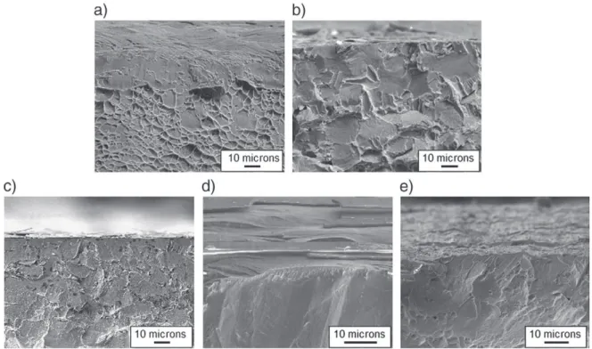
Fig. 7show the fracture surface.
The behavior of the coating prepared at 700 °C differs from the other two. It is indeed present even at the edge of the fracture surface. Only the surface which was exposed to NaCl was affected by hot salt corrosion. The other side (not corroded) and the heart seem ductile specimens. The proportion of ductile and brittle areas was estimated
Fig. 6. Electron backscattered images of the surface of the samples after tensile tests: observations away from the rupture zone of the coatings deposited at (a) 350 °C, (b) 480 °C, (c) 700 °C; observations of the rupture zone of the coatings deposited at (d) 350 °C, (e) 480 °C, (f) 700 °C.
Table 4
Influence of salt corrosion at high temperature on the mechanical properties of coated and uncoated samples.
Ti6Al4V Test conditions Yield strength (MPa) Ductility (%) Brittle area/ductile area
Not coated 850 11.13 0
Not coated Oxidation — 450 °C/100 h — air 850 11.03 0.05
Not coated Hot corrosion with NaCl — 450 °C/100 h — air 805 4.06 0.23
Coatings elaborated at 350 °C Hot corrosion with NaCl — 450 °C/100 h — air 880 4.9 0.11
Coatings elaborated at 480 °C Hot corrosion with NaCl — 450 °C/100 h — air 845 3.21 0.05
by image analysis with the software AREAS Microvision (Table 4). The specimens with a coating prepared at 480 °C or 700 °C present a poor percentage of brittle area unlike the deposit prepared at 350 °C. With a deposit prepared at 480 °C and 700 °C, the percentage of area ratio percentage of fragile ductile zone is comparable to that of a non-corroded specimen heat treated 100 h at 450 °C.
4. Conclusions
Completely amorphous and nanocrystalline/amorphous, stoichio-metric and hydroxylated aluminum oxide coatings were processed on Ti6Al4V titanium alloy and on Si substrates by MOCVD. Their mechanical properties and adhesion to the substrates were investi-gated by indentation, scratch and micro tensile tests. Amorphous Al2O3 coatings deposited at 480 °C present the highest hardness,
equal to 10.8 ± 0.8 GPa. Similar trends are obtained for the stiffness of the coatings. Adhesive and cohesive failure is observed for amor-phous and nanocrystalline coatings, respectively. Progressive crack-ing is observed for the latter durcrack-ing micro tensile tests. The mechanical strength of the coated samples is similar to that of the as processed uncoated ones. After high temperature salt corrosion test, the mechanical strength of the coated Ti alloys is higher than that of the uncoated alloys, revealing that the films allow maintaining good mechanical properties in the targeted operating conditions. However, only the nanocrystalline coating supports the decrease of ductility recorded after corrosion test on Ti6Al4V. The as established processing–structure–properties relation paves the way to engineer MOCVD aluminum oxide complex coatings which meet the specifica-tions of the high temperature corrosion protection of titanium alloys with regard to the targeted applications. The next step to meet this objective is the surface preparation of the substrate so as to accom-modate the mechanical characteristics of the amorphous coatings;
i.e. the ones that present the best barrier properties. Beyond the protec-tion of Ti6Al4V the present work is expected to be useful for the imple-mentation of such surface treatments on other pieces, for example those used in wafer tool machining.
References
[1] V.A.C. Haanappel, H.D. VanCorbach, R. Hofman, R.W.J. Morssinkhof, T. Fransen, P.J. Gellings, High Temp. Mater. Processes 15 (4) (1996) 245.
[2] M.M. Sovar, D. Samelor, A.N. Gleizes, C. Vahlas, Surf. Coat. Technol. 201 (22–23) (2007) 9159.
[3] M.M. Sovar, D. Samelor, A. Gleizes, P. Alphonse, S. Perisanu, C. Vahlas, Adv. Mater. Res. 23 (2007) 245.
[4] A.M. Huntz, M. Andrieux, C. Vahlas, M.M. Sovar, D. Samélor, A.N. Gleizes, J. Electrochem. Soc. 154 (5) (2007) P63.
[5] A.N. Gleizes, C. Vahlas, M.M. Sovar, D. Samelor, M.C. Lafont, Chem. Vap. Depos. 13 (2007) 23.
[6] A. Gleizes, M.M. Sovar, D. Samelor, C. Vahlas, Adv. Sci. Technol. 45 (2006) 1184. [7] J.-D. Beguin, D. Samelor, A.N. Gleizes, J.A. Petit, B. Sheldon, Mater. Sci. Forum
595–598 (2008) 719.
[8] J.D. Beguin, D. Adrian, J.A. Petit, J.P. Rivière, C. Vahlas, Proceedings of the 20th International Conference on Surface Modification Technologies (ASM International), 2007, p. 59.
[9] W.C. Oliver, G.M. Pharr, J. Mater. Res. 7–6 (1992) 1564. [10] H. Weiss, Surf. Coat. Technol. 71 (1995) 201.
[11] K.L. Mittal, in: K.L. Mittal (Ed.), Adhesion Measurement of Films and Coatings, 1995, p. 1.
[12] T. Ohmura, S. Matsuoka, Surf. Coat. Technol. 169–170 (2003) 728. [13] D.C. Agrawal, R. Raj, Acta Metall. 37 (1989) 1265.
[14] B.F. Chen, J. Hwang, I.F. Chen, G.P. Yu, J.H. Huang, Surf. Coat. Technol. 126 (2000) 91.
[15] B.F. Chen, J. Hwang, G.P. Yu, J.H. Huang, Thin Solid Films 352 (1999) 173. [16] R.L. Ashbrook, Nasa Technical Note, NASA TN D-4999 (1969).
[17] M. Bauccio, ASM Engineered Materials Reference Book, Second Edition, ASM International, Materials Park, OH, 1994.
[18] V.A.C. Haanappel, D.v.d. Vendel, H.S.C. Metselaar, H.D. van Corbach, T. Fransen, P.J. Gellings, Thin Solid Films 254 (1995) 153.
[19] S.J. Bull, Tribol. Int. 30 (7) (1997) 491.
Fig. 7. Observations of fracture surfaces (a) Ti6Al4V — 100 h — 450 °C, (b) Ti6Al4V — corroded with NaCl — 100 h — 450 °C, (c) coatings deposited at 350 °C on Ti6Al4V — corroded with NaCl — 100 h — 450 °C, (d) coatings deposited at 480 °C on Ti6Al4V — corroded with NaCl — 100 h — 450 °C, (e) coatings deposited at 700 °C on Ti6Al4V — corroded with NaCl — 100 h — 450 °C.