UNIVERSITÉ DE MONTRÉAL
PROPERTIES OF LIGHTNING STRIKE PROTECTION COATINGS
MARTIN GAGNÉ
DÉPARTEMENT DE GÉNIE PHYSIQUE ÉCOLE POLYTECHNIQUE DE MONTRÉAL
MÉMOIRE PRÉSENTÉ EN VUE DE L’OBTENTION DU DIPLÔME DE MAÎTRISE ÈS SCIENCES APPLIQUÉES
(GÉNIE PHYSIQUE) AVRIL 2016
UNIVERSITÉ DE MONTRÉAL
ÉCOLE POLYTECHNIQUE DE MONTRÉAL
Ce mémoire intitulé :
PROPERTIES OF LIGHTNING STRIKE PROTECTION COATINGS
présenté par : GAGNÉ Martin
en vue de l’obtention du diplôme de : Maîtrise ès Sciences Appliquées a été dûment accepté par le jury d’examen constitué de :
M. YELON Arthur, Ph. D., président
Mme KLEMBERG-SAPIEHA Jolanta-Ewa, Doctorat, membre et directrice de recherche M. MARTINU Ludvik, Ph. D., membre
DEDICATION
ACKNOWLEDGEMENTS
I would like to give thanks to the Consortium for Research and Innovation in Aerospace in Quebec (CRIAQ), Bombardier Aerospace, Bell Helicopter and 3M Canada for financing and helping for this project and thesis. Particular, or special, appreciation goes to Alexandra Desautels, Judith Roberge and the technical staff from Bell Helicopter, and Mario Simard from Bombardier Aerospace and Daniel Therriault the project leader. I thank the CRIAQ COMP-502 composite team member Dr. Thomas Schmitt for his given useful technical advice with the characterization of the coated samples, as well as other members such as Xavier Cauchy and Rajesh Ponnada for their help and collaboration.
I also want to acknowledge the help of the LM2 technicians for help with mechanical tests, Isabella Nowlan and Martin Cardonne, and the LM2 students who worked on this project but could still find time to help me with various ideas and their aid, such as Rouhollah Dermanaki Farahani.
Thanks to Professor Frederic Sirois and Masters Student Kevin McMeekin in the electrical engineering department for help with electrical equipment and concepts.
I would also like to thank the personnel at FCSEL for various aid, help and advice throughout my thesis, the technicians Francis Turcot and Sébastien Chénard, and the students Julien Schmitt, Simon Loquai, Michael Laberge, William Trottier-Lapointe and Thomas Poirié. Also special thanks to Jiri Kohout, Ph.D., who fabricated the aluminum samples for us.
Last but not least I want to thank my director Jolanta Ewa Klemberg-Sapieha, who motivated me to push my limits and excel at what I do.
RÉSUMÉ
Les matériaux composites sont de plus en plus utilisés dans plusieurs domaines. Dans le cas des compagnies aéronautiques, ces matériaux sont introduits dans leurs avions pour réduire le poids et ainsi réduire les coûts de carburants. Ces avions sont donc plus légers mais la perte de conductivité électrique rend l'avion vulnérable à la foudre ; celle-ci peut frapper les avions commerciaux en moyenne une fois par an. La protection contre la foudre devient donc très importante. Les mailles de cuivre actuelles offrent une bonne protection mais elles augmentent le poids des composites. Dans le cadre du projet CRIAQ COMP-502, une équipe de partenaires industriels et de chercheurs académiques étudient de nouveaux revêtements conducteurs ayant les caractéristiques suivantes : bonne protection électromagnétique, résistance mécanique élevée, bonne protection contre l'environnement, bonne fabricabilité et des coûts modérés. Les objectifs principaux de ce mémoire, dans le cadre de ce projet, était de déterminer les caractéristiques principales (électriques et tribomécaniques) pour les revêtements conducteurs placés sur les panneaux composites. Leurs propriétés étaient également testées après des essais destructifs tels que des injections de courants et des essais environnementaux.
Bombardier Aerospace a fourni le substrat, un matériau composite constitué de fibres de carbone qui renforcent une matrice époxy, et le produit commercial actuel, un film surfacique (surfacing
film) qui comprend une feuille de cuivre déployé (expanded copper foil) pour comparer avec les
autres revêtements. Voici la liste des revêtements conducteurs fabriqués par les étudiants: des nanoparticules d'argent dans une matrice (PEDOT:PSS ou un mélange d'époxy et de PEDOT:PSS); des nanofibres de carbone couvertes d'argent et intégrées dans le film de surface; un revêtement d'étain par projection à froid (cold spray); du graphène oxydé et fonctionnalisé (functionalized) avec des nanofils d'argent et un dépôt d'argent autocatalytique (electroless
plating). De plus, dans le cadre du projet et mémoire, des revêtements d'aluminium ont été
pulvérisés à l’aide d’un magnétron.
Il y a trois principaux types de tests pour caractériser les revêtements conducteurs : électriques, mécaniques et environnementaux. Les tests électriques consistent à trouver la résistance-carré et la résistivité spécifique des revêtements conducteurs. Les tests mécaniques comprennent l'adhérence, le test d'éraflure, la dureté et le module de Young des revêtements. Les tests environnementaux comprennent des cycles thermiques et embrun salin (salt spray). Ces
caractéristiques de base sont étudiées en premier, mais d'autres tests combinent les catégories ensemble, comme des tests électriques avant, pendant et après les tests environnementaux ainsi que les effets des injections de courants électriques sur les propriétés mécaniques de l'échantillon. Les propriétés électriques des revêtements conducteurs ont été améliorées et sont très proches de celles des mailles de cuivres métalliques ou dans un ordre de grandeur similaire. Les propriétés mécaniques sont également bonnes pour la plupart de ces revêtements ; elles montrent une bonne adhérence et dureté. Elles ne montrent aucune perte significative des propriétés de flexion après des injections de courant. Les tests environnementaux sont plus mitigés : certains revêtements conducteurs perdent leur conductivité sur leurs surfaces, d’autres avaient une légère augmentation de leur résistivité et quelques-uns n’étaient pas affectés. D'autres tests comme l'analyse thermogravimétrique, ou l’analyse des tests d'éraflure par microscope électronique à balayage ainsi que des observations par microscope optique sont inclus pour l'analyse supplémentaire des résultats des revêtements conducteurs.
Les revêtements conducteurs ont été caractérisés et testés dans le cadre du projet CRIAQ. Des tests de coup de foudre sont nécessaires pour recueillir de plus amples informations sur ces revêtements. L'application principale de ces revêtements est la protection contre la foudre pour les avions, mais ils peuvent aussi être utilisés pour la protection contre la foudre sur le sol et pour la protection électromagnétique.
ABSTRACT
Composite materials are being increasingly used by many industries. In the case of aerospace companies, those materials are installed on their aircraft to save weight, and thus, fuel costs. These aircraft are lighter, but the loss of electrical conductivity makes aircraft vulnerable to lightning strikes, which hit commercial aircrafts on average once per year. This makes lightning strike protection very important, and while current metallic expanded copper foils offer good protection, they increase the weight of composites. Therefore, under the CRIAQ COMP-502 project, a team of industrial partners and academic researchers are investigating new conductive coatings with the following characteristics: High electromagnetic protection, high mechanical resistance, good environmental protection, manufacturability and moderate cost. The main objectives of this thesis, as part of this project, was to determine the main characteristics, such as electrical and tribomechanical properties, of conductive coatings on composite panels. Their properties were also to be tested after destructive tests such as current injection and environmental testing.
Bombardier Aerospace provided the substrate, a composite of carbon fiber reinforced epoxy matrix, and the current commercial product, a surfacing film that includes an expanded copper foil used to compare with the other coatings. The conductive coatings fabricated by the students are: silver nanoparticles inside a binding matrix (PEDOT:PSS or a mix of Epoxy and PEDOT:PSS), silvered carbon nanofibers embedded in the surfacing film, cold sprayed tin, graphene oxide functionalized with silver nanowires, and electroless plated silver. Additionally as part of the project and thesis, magnetron sputtered aluminum coated samples were fabricated. There are three main types of tests to characterize the conductive coatings: electrical, mechanical and environmental. Electrical tests consist of finding the sheet resistance and specific resistivity of conductive coatings. Mechanical tests include adhesion, scratch, hardness and Young's modulus of the coatings. The environmental tests are temperature cycling and salt spray cycling. These basic characteristics were investigated first, but further tests also combine the categories, such as electrical tests before, during and after environmental tests, and the effects on the sample's mechanical properties after high electrical current injections.
The electrical properties of the conductive coatings have improved and are very close to that of current expanded metallic foil or within an order of magnitude. The mechanical properties of
most of these coatings are also good. They exhibit good adhesion, hardness, and no significant loss of flexion properties after current injections. The environmental tests are more mitigated, with some conductive coatings losing their surface conductivity, others having a small increase in specific resistivity, and some were simply unaffected. Tests such as thermogravimetric analysis, scanning electron microscope analysis of scratch tests, and optical microscope observations are included to provide additional analysis of the results of the conductive coatings.
The conductive coatings were characterized and tested as part of the CRIAQ project. Lightning strike tests are required to gather further information on these conductive coatings. The main application for these coatings is for lightning strike protection of aircraft, but they can also be used for ground based lightning strike protection and general electromagnetic shielding.
TABLE OF CONTENTS
DEDICATION ... III ACKNOWLEDGEMENTS ... IV RÉSUMÉ ... V ABSTRACT ...VII TABLE OF CONTENTS ... IX LIST OF TABLES ... XIII LIST OF FIGURES ... XIV LIST OF SYMBOLS AND ABBREVIATIONS... XVIII LIST OF APPENDICES ... XXCHAPTER 1 INTRODUCTION ... 1
1.1 LSP Principles ... 2
1.2 Regulations and Standards ... 2
1.3 Present LSP Coatings ... 5
1.4 Objectives ... 6
1.5 Sections Outline ... 6
CHAPTER 2 BACKGROUND ... 8
2.1 Properties of LSP Metallic Materials ... 8
2.2 Metal Meshes ... 8
2.3 Metal Coated Fibers ... 10
2.4 Metallic Coating Processes ... 10
2.4.1 Magnetron Sputtering ... 10
2.4.2 Electroless Plating ... 11
2.5 Metallic Nanowires ... 13
2.6 Carbon Nanotubes ... 13
2.7 Graphene ... 13
2.8 Synergy between Graphene and CNT ... 14
2.9 LSP Nanoparticles and Percolation Networks ... 14
2.10 Electrical Tests of LSP Coatings ... 16
2.11 Mechanical Testing of LSP Coatings ... 18
CHAPTER 3 METHODOLOGY ... 20
3.1 LSP Conductive Coatings ... 21
3.1.1 Baseline Substrates-Composite (Carbon/Epoxy) with no LSP (CFRP) ... 21
3.1.2 Baseline Substrates-Composite (Carbon/Epoxy) with Expanded Copper Foil within Surfacing Film Cytec SurfaceMaster 905C (ECF/SF) ... 22
3.1.3 Silver Nanoparticles in Matrix (Nano Ag) ... 22
3.1.4 Silver-Coated Carbon Nanofibers (Ag CNF) ... 22
3.1.5 Cold Sprayed Tin (CS Sn) ... 23
3.1.6 Graphene Oxide and Silver Nanowires in PEDOT:PSS Resin (GO AgNW) ... 23
3.1.7 Electroless Plated Silver (EP Ag)... 23
3.1.8 Magnetron Sputtered Aluminum (MS Al) ... 24
3.2 Morphology/SEM/Optical Microscope ... 24
3.3 Electrical Characterization ... 25
3.3.1 4-Point Probe on Coating ... 25
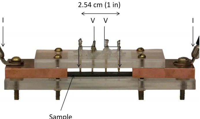
3.3.2 Four-Terminal Sensing ... 27
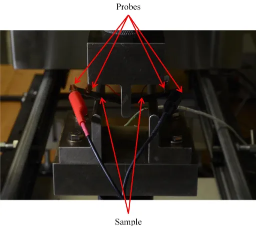
3.3.3 Change in Resistance During Flexion Tests ... 28
3.3.4 4 Point Probe for Environmental Tests ... 29
3.4 Thermogravimetric Analysis ... 30
3.5 Mechanical Characterization ... 30
3.5.1 Adhesion Tape Test ... 31
3.5.2 Scratch Test ... 33
3.5.3 Indentation Test ... 33
3.5.4 Sample Preparations for Flexion Test ... 34
3.5.5 Three-Point Flexion ... 35
3.5.6 Tribology ... 36
3.6 Environmental Characterization ... 36
3.6.1 Thermal (Temperature) Cycling ... 36
3.6.2 Salt Spray (Fog) Exposure ... 37
CHAPTER 4 EXPERIMENTAL RESULTS AND ANALYSIS ... 39
4.1 Coating Densities and Thicknesses ... 39
4.2 Electrical Properties of Different LSP Coatings ... 40
4.2.1 Silver Nanoparticles in Matrix ... 40
4.2.2 Cold Sprayed Tin ... 42
4.2.3 Graphene Oxide Functionalized with Silver Nanowires ... 44
4.2.4 Electroless Plated Silver ... 45
4.2.5 Magnetron Sputtered Aluminum ... 46
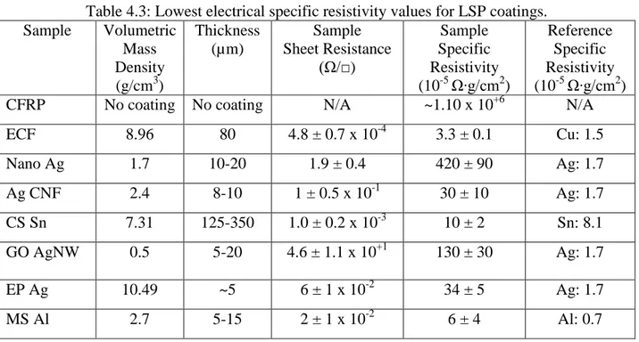
4.2.6 Comparisons of Electrical Values ... 47
4.2.7 Change in Specific Resistivity Before and After Current Injections During Flexion Tests ... 48
4.3 Mechanical Properties ... 50
4.3.1 Adhesion Tape Test Results ... 50
4.3.3 Indentation Test Results ... 61
4.3.4 Three Point Flexion Test Results ... 62
4.3.5 Tribology Results ... 64
4.4 Environmental Test Results ... 67
4.4.1 Thermal (Temperature) Cycling ... 67
4.4.2 Salt Spray (Fog) Cycling ... 69
CHAPTER 5 CONCLUSIONS AND RECOMMENDATIONS... 72
5.1 Summary and General Discussion ... 72
5.2 Conclusion ... 75
5.3 Perspectives ... 75
BIBLIOGRAPHY ... 77
LIST OF TABLES
Table 1.1: Overview of select LSP products [17]. ... 5
Table 2.1: Volumetric mass density, volume resistivity and specific resistivity for metallic and carbon materials [17]. ... 17
Table 3.1: List of all LSP conductive coatings. ... 21
Table 4.1: Volumetric mass density of LSP coatings. ... 39
Table 4.2: Thickness of LSP coatings. ... 40
Table 4.3: Lowest electrical specific resistivity values for LSP coatings. ... 47
Table 4.4: Currents injected in the sample or its conductive coating. ... 48
Table 4.5: Average increase for specific resistivity of each sample groups, with and without current injections, and the standard deviation of each sample group. ... 49
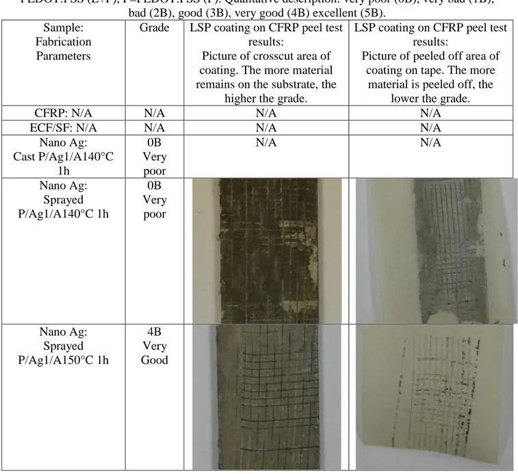
Table 4.6: Adhesion grade for LSP coatings based ASTM D3359 Procedure B. Epoxy and PEDOT:PSS (E+P), P=PEDOT:PSS (P). Qualitative description: very poor (0B), very bad (1B), bad (2B), good (3B), very good (4B) excellent (5B). ... 51
Table 4.7: Hardness and Young's Modulus for LSP coatings. ... 62
Table 4.8: Coefficient of friction for LSP coatings. ... 66
Table 4.9: Change in specific resistivity of samples after each thermal cycle. ... 69
LIST OF FIGURES
Figure 1.1: Aircraft struck by a lightning strike [7]. ... 1
Figure 1.2: Lightning strike zones according to SAE ARP 5414 [14] [17]. ... 4
Figure 1.3: Lightning strike simulation according to SAE ARP 5412 [18]. ... 4
Figure 2.1: a) Woven mesh design [28, 29]. b) Typical metallic perforated mesh (expanded metal foil) [17, 30, 31] image courtesy of Dexmet Corporation. ... 9
Figure 2.2: Typical layup showing position of metal mesh from StrikeGrid™ Continuous expanded aluminum foil brochure [15]. ... 10
Figure 2.3: SEM image of copper (light area) coating on aluminum (dark area) [50]. ... 12
Figure 2.4: Volume resistivity of cold spray aluminum layers at different gas temperatures and of plasma sprayed aluminum [51]. ... 12
Figure 2.5: A hybrid of CNT and FLG mixing to creature a hybrid paper [17] [70]. ... 14
Figure 2.6: Volume resistivity vs. filler volume fraction [17] [79]. ... 15
Figure 2.7: Tension and compression strength (in kilopound per square inch) vs. injected current for unnotched specimens in tension (UNT) and compression (UNC) [4]. ... 19
Figure 3.1: Three locations of electrical resistance measured for the 12.7 cm x 1.27 cm (5x0.5in) samples in the middle and 2.54 cm (1 in) from the sample ends. ... 25
Figure 3.2: Diagram for electrical measurement of specific resistivity of 4-point probe method [87]. ... 26
Figure 3.3: Correction factor based on geometry of the sample measured [88] [89]. ... 26
Figure 3.4: Four-terminal sensing by uniform current distribution. ... 28
Figure 3.5: In progress electrical characterization of sample during 3-point flexion test. ... 29
Figure 3.6: Cross-scratch results and cutting handheld tool [90]. ... 31
Figure 3.7: Classification of adhesion test results from standard ASTM D3359 – 09 Method B [90]. ... 32
Figure 3.8: Scratch test diagram of substrate and application of progressively increasing load FN
from indenter. ... 33 Figure 3.9: Load/displacement curve [92]. ... 34 Figure 3.10: 3-point flexion test. The film coating is at the bottom of the specimen and therefore
in tension during testing. ... 35 Figure 3.11: Picture/diagram of pin on disk setup. ... 36 Figure 3.12: Thermal cycling between -55°C (-67°F) and +121°C (248°F). ... 37 Figure 3.13: Location of exposed area 7.62 x 2.54 cm (3x1 in) and X scribe 4 mils wide (0.1 mm)
on panel size 12.7 x 7.62 cm (5x3 in). ... 38 Figure 4.1: TGA results a) Ag1 b) Ag2. ... 41 Figure 4.2: Specific resistivity of silver nanoparticles in matrix. First sample was cast, other
coatings sprayed onto substrate. Annealing temperatures (A140°C, A180°C and A200°C) for one hour. P = PEDOT:PSS matrix, E = Epoxy and PEDOT:PSS mixture. ... 41 Figure 4.3: Specific resistivity of cold sprayed tin conductive coatings. Pressure and temperature
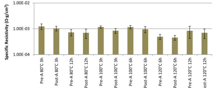
parameters during cold spray. Samples of 10, 30 or 50% copper (Cu) powder or 10% zinc (Zn) powder, the remainder being tin (Sn) powder. Annealed (A) samples from 1, 3, 6, 12, 24, 48 and 72 hours, or for 1, 7 and 12 hours. ... 43 Figure 4.4: Specific resistivity of graphene oxide functionalized with silver nanowires. ... 44 Figure 4.5: Specific resistivity of electroless plated silver on substrate. Includes fabrication
parameters and pre/post annealing (A) differences at various durations (3, 6 and 12 hours) and temperatures. ... 45 Figure 4.6: Specific resistivity of sputtered aluminum. Pretreatment (pre-T) with Argon ions. The
long deposition time (3h dep) of 3 hours and the short deposition time (6x0.5h dep) of six deposition periods of 30 minutes with a 30 minutes pause in between. ... 46 Figure 4.7: Increases of the specific resistivity of LSP coatings after current injections as strain
increases from 3-point flexion test for a) cold sprayed tin (CS Sn) injected with 50 A and b) expanded copper foil (ECF) injected with 25 A. ... 49
Figure 4.8: Scratch results for samples CFRP and ECF/SF. No debris found on the surface. ... 56 Figure 4.9: Penetration (Pd) and residual (Rd) depth for CFRP and ECF/SF samples... 56 Figure 4.10: Scratch results at 10 N for Nano Ag samples with Ag-2 ink. Annealed for one hour,
with Epoxy and PEDOT:PSS (E+P) at a) 140°C, b) 180°C, c) 200°C, and PEDOT:PSS only (P) at d) 140°C, e) 180°C, f) 200°C. ... 57 Figure 4.11: Penetration (Pd) and residual (Rd) depths for samples with silver nanoparticles
(Nano Ag), Epoxy and PEDOT:PSS (E+P) and Pedot:PSS (P) matrix, with Ag2-Ink (Ag2) and Annealing (A) at 140°C, 180°C, and 200°C for 1 hour. Note: Colors do not represent the different conductive coatings from Table 3.1: List of all LSP conductive coatings.. ... 58 Figure 4.12: Penetration (Pd) and residual (Rd) depths for samples with silver nanoparticles
(Nano Ag), Pedot:PSS (P) matrix, with Ag2-Ink (Ag2) and Annealing (A) at 140°C, 180°C, and 200°C for 1 hour. Note: Colors do not represent the different conductive coatings from Table 3.1: List of all LSP conductive coatings. ... 59 Figure 4.13: Scratch results at 10 N of LSP conductive coatings a) CS Sn, b) GO AgNW, c) EP
Ag, d) MS Al. ... 60 Figure 4.14: Penetration (Pd) and residual (Rd) depths for CS Sn, GO AgNW, EP Ag and MS Al
samples. ... 61 Figure 4.15: Load/displacement curves. Representative curves show the harder materials (on the
left) compared to softer ones (on the right). ... 62 Figure 4.16: Flexural strength for all samples after: no injection, 5A, 25A, 50A, 100A current
injected. ... 63 Figure 4.17: Flexion elastic modulus for all samples after 5A, 25A, 50A, 100A current injected. ... 64 Figure 4.18: Coefficient of friction for CFRP for distances 25, 50, 100, 200, 400, and 800 m... 65 Figure 4.19: Coefficient of friction for ECF/SF for distances 25, 50, 100, 200, 400, and 800 m. 65 Figure 4.20: Coefficient of friction for CS Sn for distances 25, 50, 100 and 200 m. ... 66 Figure 4.21: Specific resistivity of samples at the start and after each thermal cycle. ... 68
Figure 4.22: Specific resistivity of samples at the start and after each salt spray cycle. ... 70 Figure 5.1: Lowest electrical specific resistivity values for baselines CFRP substrate and ECF,
and LSP coatings. ... 72 Figure 5.2: Baselines CFRP substrate and ECF/SF, and all LSP coatings values for a) hardness
and b) Young's Modulus. ... 73 Figure 5.3: Summary of coefficients of friction. ... 74
LIST OF SYMBOLS AND ABBREVIATIONS
The list of symbols and abbreviations presents the symbols and abbreviations used in the thesis or dissertation in alphabetical order, along with their meanings:
A Ampere
AFN Advanced Fiber Nonwovens
ARP Aerospace Recommended Practices
BP Buckypaper
CC/CS Conductive Coating/Composite Structure
CF Correction Factor
CFRP Carbon Fiber Resin Polymer CNFP Carbon Nanofiber Papers CNT Carbon Nanotube
CRIAQ Consortium for Research and Innovation in Aerospace in Quebec CP-CNFP Composite Panel Carbon Nanofiber Papers
EMI Electromagnetic Interference EPT Electrical Percolation Threshold ECF Expanded Copper Foil
FAA Federal Aviation Agency FHC Filled-Hole Compression FHT Filled-Hole Tension FLG Few-Layer Graphene FRP Fiber Reinforced Polymer
HiPIMS High Power Impulse Magnetron Sputtering
LSP Lightning Strike Protection LWD Long Width Diamond MGP Multi-Graphene Platelets MWCNT Multi-Walled Carbon Nanotube
Pd Penetration Depth
PEDTOS:PSS Poly(3,4-Ethylenedioxythiophene) Polystyrene Sulfonate PSF Pound per Square Feet
PSI Pound per Square Inch
RD Residual Depth
RF Radio Frequency
SAE Society of Automotive Engineers SEM Scanning Electron Microscope
SF Surfacing Film
SPS Spark Plasma Sintering
SWCNT Single-walled Carbon Nanotube SWD Short Width Diamond
TGA Thermogravimetric Analysis UNT Unnotched Tension
LIST OF APPENDICES
Appendix A – Environment Report Figures ... 84 Appendix B – Lists of Papers as Author and Co-Author ... 93
CHAPTER 1
INTRODUCTION
Commercial aircraft are struck by lightning once every 1,000-10,000 hours of flight, or about once a year [1], as shown in Figure 1.1. Electrical currents as high as 200,000 Amperes (A) travel through the least resistant parts of the aircraft, and if the aircraft is not well protected, severe consequences such as vaporization of critical aircraft parts can follow [2]. Aircraft were usually made of aluminum before composites were introduced around 40 years ago [3]. It provided the necessary electrical conductivity to keep the aircraft and its systems, such as onboard electronics or metallic control cables, safe [4]. The aircraft antenna is protected by a radome, which diverts the strike to the grounded section of the aircraft while allowing electromagnetic waves used for communications [5, 6].
Figure 1.1: Aircraft struck by a lightning strike [7].
Aircraft companies are investing in research to change from metal structures to composite structures with high mechanical properties to reduce overall weight of the aircraft, leading to fuel savings for environmental and monetary benefits [8]. Fiber reinforced polymer (FRP) composites, even those made of carbon fibers, are unable to carry the high currents and electromagnetic forces to prevent lightning damage on the aircraft. There is a need for lightning strike protection (LSP) to prevent damage such as embrittlement, delamination of composite fiber/matrix and/or structural failure [2]. The LSP system must be able to carry high currents and electromagnetic interference (EMI) forces generated by a lightning strike. It lets the current flow through the protected aircraft without causing damage and to exit towards the ground. Damage occurs where the current is densest, usually at the entrance or exit of a lightning strike. The current commercial product for LSP is a copper or aluminum expanded metallic foil adhered to the surface of the composite panels. Other materials, such as nickel [6] and phosphorus bronze [9], were used but the additional weight negated the weight savings from using composite materials.
1.1 LSP Principles
Lightning commonly strikes an aircraft when it passes through a storm cloud or during landing/takeoff moments [10]. There are a few types of lightning strikes, such as cloud to ground, cloud to cloud, ground to cloud, which is also called a return stroke, and intracloud, which is within the cloud itself and occurs more commonly on aircraft than ground strikes do [5, 11]. Lighting usually strikes the aircraft's nose, wing tip or another extremity, and the current will take the shortest and most conductive path possible to exit at another extremity, completing the 'electrical circuit' [2]. Due to the aircraft moving during a lightning strike, the lightning discharge will be 'swept' along the aircraft for a short distance. Lightning current flows through an attachment point which is called the hang on. The entry and exit points of a strike will have the largest density of energy/current of the lightning strike. Very high energy densities can result in material vaporization, while this energy spike can be more quickly diffused in high conductivity materials. A lightning strike's type and magnitude of damage depends on its energy level, the LSP surface materials, the underlying composite type and layup (the fiber orientations and stacking order), as well as paint thickness [8]. Therefore the LSP's main goal is to keep the lightning current on the exterior and quickly exit the aircraft by providing an electrically conductive path on the exterior structure [2].
1.2 Regulations and Standards
Preventing catastrophic structural damage, hazardous electrical shocks and loss of flight control are the main objectives for developing LSP. Metallic frame aircraft can do this [5] but non-metallic components have more difficulty minimizing the effects of a direct lightning strike or a high amperage current [12]. There are government agencies, military standards as well as organizations such as Society of Automotive Engineers (SAE) and aircraft manufacturers who all have their own standards and internal requirements to address LSP [4].
The important LSP standards and regulations are described below. According to Federal Aviation Administration (FAA) regulations Advisory Circular AC 25–21, Section 25.581 “Lightning Protection of Structure”, an aircraft struck by lightning must be able to continue to fly and perform normal operations [12]. Current industry standards like the SAE Aerospace Recommended Practices (ARP) contain guidelines and tests to pass government regulations, as
there is no minimum electrical conductivity to pass the standards and regulations, though higher conductivity materials undergo less damage than more resistive [13]. This can be seen during lightning tests on panels where more conductive materials do not have damage that penetrates the panel or is smaller in area [13]. Simulated lightning waveforms and aircraft zones demonstrate lightning strike phenomena according to the SAE ARP 5412 and 5414 standards. By using different protection layers in different zones it is possible to tailor the aircraft lightning protection to reduce the weight while still keeping the aircraft protected.
The six lightning strike zones, seen in Figure 1.2 for a commercial aircraft, determined by SAE ARP 5414 represent the probability of being struck by lightning and subjected by the various density currents. This is one of the steps required to show the aircraft is protected [14]. These zones, determined by laboratory lightning strike tests, are represented thus [5, 11]:
Zone 1: High likelihood of initial lightning strike attaching itself to the frame at attachment point with first return strokes.
Zone 1A: Low expectation of hang on.
Zone 1B: High expectation of hang on.
Zone 1C: First return stroke of reduced amplitude and low expectation of hang on.
Zone 2: Likelihood of having subsequent swept strokes or re-strikes. Swept strokes occur as the aircraft traverses a lightning channel such that the strike 'sweeps' across the surface. Zone 2A: Low expectation of hang on.
Zone 2B: High expectation of hang on.
Zone 3: Supports large currents between areas of attachment points.
Standard SAE ARP 5412 shows four lightning flash current waveforms named A-D as seen in Figure 1.3 recommended to emulate lightning strikes and evaluate their effects. Each zone mentioned in standard SAE ARP 5414 is required to sustain certain of these current waveforms, such as an A component which can go up to 200,000 A [15]. Component A simulates the first return stroke, components B and C the long duration of currents following a strike due to the aircraft moving and return strokes causing long duration currents, while components D are the subsequent stroke. Zone 1 needs to be able to protect against waveform A while Zone 2 need only protect against component D, which is lower in current amplitude than A. A lightning generator was fabricated for the project for A-component strikes. Tests for lightning strikes are normally passed or failed only and depend on whether aircraft safety has been compromised or not by the damage resulting from the strike [5].
Materials used for LSP must be able to contain large currents in amplitude and density according to the SAE and AC standards. Zone 1 requires better protection as higher current densities must be able to pass through them, unlike Zone 2 and 3, which have a more dispersed current density. Some graphite/carbon fiber composites in Zone 2 do not require additional LSP [5]. Other standards are listed in Table 1.1 and deal with tangentially related safeguards such as the protection of fuel systems against ignition from lightning strikes and electronic equipment protection [16].
Figure 1.2: Lightning strike zones according to SAE ARP 5414 [14] [17].
Figure 1.3: Lightning strike simulation according to SAE ARP 5412 [18].
TIME (NOT TO SCALE)
≤ 500 µs ≤ 5 ms 0.25 ≤ T ≤ 1 s ≤ 500 µs C U R R EN T (N O T TO S C A L
E) COMPONENT B (Intermediate Current)
Maximum Charge Transfer = 10 Coulombs Average Amplitude = 2 kA ± 10%
COMPONENT C (Continuing Current) Charge Transfer = 200 Coulombs ± 20%
Amplitude = 200 - 800 A
COMPONENT D (Restrike) Peak Amplitude = 100 kA ± 10%
Action Integral = 0.25 x10⁶ A2s ± 20%
COMPONENT A (Initial Stroke) Peak Amplitude = 200 kA ± 10%
Action Integral = 2 x10⁶ A2s ± 20%
1.3 Present LSP Coatings
LSP materials can be applied on the outer surface (coating) or embedded inside the composite structure (embedded conductive fibers inside the composite laminate, resin modifications with fillers to improve its electrical conductivity) [3].
Table 1.1 shows many of the currently available commercial products, most of which consist of metallic mesh or expanded foil bonded with modified resin bonded to the composite surface.
Table 1.1: Overview of select LSP products [17].
Type of LSP Example of configuration
Commercial product Main characteristics
Metallic mesh or foil bonded with
resin
Mesh materials (copper, aluminum, bronze, titanium)
Resin materials (epoxy, vinyl ester, modified epoxy) Prepreg materials Astrostrike by Astroseal Products Mfg. Corp. MicroGrid by Dexmet Corp. Strikegrid by Alcore Corp. HexWeb CR-PAA by Hexcel Corp. High conductivity of metal
Heavy surface material Problem with porosity
Metal or metalized fibers bonded with resin Fibers, woven or non-woven screens (carbon, graphite, glass, polyester, synthetic fibers) Coatings (nickel, copper, silver, platinum)
Coated fibers by Metal Coated Fibers Metal hybrids by Electro Fiber Technologies Hexply by Hexcel Lightweight
Less efficient than mesh Flexible process (multicoating and multilayer is possible) Polymer-based film or conductive adhesives Enhanced polymer with additives Peel-and-stick by Integument Technologies Scotch-Weld by 3M Lightweight Smooth finish Must be replaced if struck
1.4 Objectives
This thesis was completed as part of a Consortium for Research and Innovation in Aerospace in Quebec project: CRIAQ COMP-502. The main objective of the CRIAQ project was to develop a lightweight conductive coating for efficient lightning strike protection of composite structures of aircraft while featuring the desired characteristics: High electromagnetic protection, high mechanical resistance, good environmental protection, manufacturability and moderate costs. Bombardier Aerospace (BA), Bell Textron Helicopter Canada (BTHC), and 3M have expressed their interests on the development of conductive films or coatings for composite structures. This multidisciplinary project required the collaboration between the industrial partners and the diversified academic research team from Polytechnique Montréal, Université du Québec a Montréal, and McGill University.
Within this project the main objective of my thesis was to determine the electrical and tribomechanical in order to evaluate the performance of surface conductive coating/composite structure systems (CC/CS) and to observe their environmental stability. In particular we study the conductive coatings (fabricated under the conditions described in Section 3.1) mechanical (hardness H, and Young's Modulus, E), tribological (coefficient of friction), and functional properties (specific resistivity) and their stability in harsh environment. The change in mechanical flexion modulus and flexural strength of the composite substrate after current injection was also studied to see the effectiveness of the conductive coating's protection of the substrate from electrical damage. These characteristics are compared with the baseline current expanded copper foil technology.
Different conductive coatings were prepared by students at different universities. Magnetron sputtered aluminum coatings were fabricated as part of this thesis. They are described in Section 3.1.
1.5 Sections Outline
After the introduction on lightning strike protection, important information on current LSP coatings and regulations is described in Chapter 1. The project and thesis objectives are then presented.
The background information of this thesis in Chapter 2 includes current and potential materials, methods and coatings from the literature for LSP. It details various materials like metallic materials, types of metal meshes, metal fibers, metal nanowires, carbon nanotubes, graphene, and synergy between the last two materials, most of which are used by the other students of the project. It describes the coating processes used by students such as magnetron sputtering, electroless plating, and thermal/cold spray. It explains important physical phenomena like electrical percolation threshold, which is an important concept for conductive coatings prepared by students working in this project.
The methodology in Chapter 3 describes the LSP conductive coatings, designs and fabrication methods by the students working in this project. Each coating uses a different fabrication method, described in some detail, but the magnetron sputtering deposition method is given in more detail and attention, as this was done as part of this thesis.
The various tests used to characterize the sample LSP conductive coating properties are explained and described in Chapter 3. This includes the electrical characterization done on the samples, including those done as part of multi-cycle thermal and salt spray tests and the mechanical characterization, which includes adhesion, scratch, indentation and three-point flexion tests. Other tests that were part of the thesis, such as Thermogravimetric Analysis (TGA), Scanning Electron Microscope (SEM) and tribological test are included in this section.
The experimental results are shown in Chapter 4, including electrical, mechanical, environmental and tribological properties. The mechanical properties include results of hardness and the Young's modulus of the coatings from indentation tests, the results of the scratch tests including SEM image and residual depth, and the changes in the flexural modulus and strength after larger electrical currents are injected. A comparison is provided between bulk materials, the baseline commercial product, and materials provided by the industrial partners, and LSP conductive coatings designed in this project.
Chapter 5 builds on Chapter 4 to present a thorough conclusion. Following that is a discussion of suggested improvements to the samples used and to the methodology of the tests, including notes on further tests that could be included in the project. Finally, additional applications of the project's results are covered.
CHAPTER 2
BACKGROUND
This background information review details many of the properties of materials, conductive coating designs and fabrication techniques used for LSP and more specifically those used in this project and thesis. Section 2.10 includes electrical properties for LSP coatings. Section 2.11 details the testing of certain mechanical properties of LSP composites. A more detailed literature review about LSP can be found in the literature review [17].
2.1 Properties of LSP Metallic Materials
Low electrically resistive materials are needed for LSP. Plastics used in aerospace composites have surface resistance near 1012 ohm/sq and are considered insulators [19]. A low volume resistivity and/or low volumetric mass density mean a low specific resistivity and thus a good choice for LSP. Some observations to note about metallic materials:
Low volume resistivity and low prices make aluminum and copper the most used materials [3].
Silver is the most conductive, but is heavy and expensive compared to copper and aluminum [20].
Galvanic corrosion occurs between aluminum and carbon[3, 21].
Some highly conductive materials have severe drawbacks that prevent their use in LSP applications:
Calcium, lithium, potassium and sodium have exothermic reactions in water and release hydrogen, which may ignite it in the atmosphere [22].
Magnesium is flammable but could be used in alloy form currently used in the aerospace domain such as magnesium alloys to reduce weight in fuselage structures [23].
Alloys traditionally have conductivity levels at about fifty percent of solid bulk metal foil materials [24].
Beryllium is expensive and toxic but currently used in the aerospace domain such as in copper/beryllium alloys to improve component service life [25].
2.2 Metal Meshes
The main LSP processes and products for LSP can be found in the literature review on lightning strike protection of aircraft [17] and Table 1.1, which includes a short list of some companies that work on LSP. The current main protection against lightning strikes is a flat metal mesh (expanded metallic foil, which is used as a comparison baseline for all conductive coatings) of aluminum or copper over the composite outer structure [5]. Non-expanded metal foil is currently
not used due to delamination, its prevention of resin bonding, and the resin underneath the foil could vaporize causing a buildup of pressure that causes greater damage to the foil from the blow out pressure [5]. Figure 2.1a shows a woven mesh, which can be made of alloys, but the contact point between strands have higher resistance and non-uniform thickness but are nonetheless still being used for LSP [20, 24, 26]. Figure 2.1b shows a non-woven mesh (expanded metal foil) that can be expanded by pulling/stretching to alter its thickness and electrical resistance, a smoother surface, and reduce the volume and weight of resin to fill the mesh [27]. A non-woven (expanded metal foil) can be made of almost pure metal, and thus have the best electrical conductivity possible [24].
Figure 2.1: a) Woven mesh design [28, 29]. b) Typical metallic perforated mesh (expanded metal foil) [17, 30, 31] image courtesy of Dexmet Corporation.
Very thin meshes can be problematic by not providing enough electrical conductivity or by being at risk of vaporization from lightning strikes [32], although that might be desirable if it helps protect the underlying structure by acting as a sacrificial layer such as LS-1000® from Integument Technologies [33]. One advantage of non-woven meshes is that they do not unravel or have loose strands, which avoids complications during fabrication or installation of LSP on composite panels, the mesh staying homogenous and smooth around shapes and contours to provide constant conductivity to the aircraft surface [31]. Metal meshes are adhered to composite panels using resins, adhesives or surfacing films. Various methods exist such as piling separate products, pre-impregnation (pre-preg), and ply-integrated solution to ensure bonding [3]. Figure 2.2 shows a conceptual schematic of the metal mesh between two adhesive films. Isolation layers may need to be added if one of the plies is an aluminum mesh in addition to the surface adhesive to adhere the metal mesh to the underlying composite as well as protect it from outside elements.
Figure 2.2: Typical layup showing position of metal mesh from StrikeGrid™ Continuous expanded aluminum foil brochure [15].
2.3 Metal Coated Fibers
Some of the other LSP products include metallic fibers, such as an interconnected network of nickel coated carbon fibers from Advanced Fiber Nonwovens (AFN) Group [34]. The use of nickel on the carbon fibers removes the need of an isolation layer to prevent galvanic corrosion. Tests were performed and were successfully passed by this coating with no structural damage or delamination of the protected panels, with most of the damage being on the surface just like an aluminum LSP panel [34]. Silver-coated carbon nanofibers use a similar concept for LSP as shown in Section 3.1.4.
2.4 Metallic Coating Processes
With metal being one of the most conductive materials available, it is also possible to coat this conductive material onto other materials such as mica [35], glass [36] or carbon [37] particles or structures. Possible methods include Physical Vapour Deposition (PVD) [38], Spark Plasma Sintering (SPS) [39, 40], or Flame Spray with aluminum [41]. Some of these methods are used in Table 1.1 such as metalized fibers provided by commercial companies for LSP products. The following deposition method, magnetron sputtering, is used in this thesis and the other methods, electroless plating and cold spray, by students in the project as shown in Section 3.1.
2.4.1 Magnetron Sputtering
This method was used as part of this thesis as shown in Section 3.1.8. One of these metallization methods is physical vapor deposition. PVD involves formation of vapors from a solid source using thermal energy (evaporation) or momentum (sputtering). It is usually performed at low pressures to allow directional transport of gaseous species from the source to the substrate. PVD
may be used for the deposition of pure materials or compounds. Compounds are frequently deposited by reactive processes. Magnetron sputtering uses electromagnetic fields to ionize the gas. It can deposit a film of a few thousand Angstroms (less than one micron) [42] of condensed elemental, alloy and compound materials. Thicker deposits can be accomplished with multiple depositions. Décor Engineering uses this method with aluminum to protect the aircraft from EMI and lightning strikes by providing multiple layers of PVD [38]. In this thesis the relatively new method of high power impulse magnetron sputtering (HiPIMS), combining magnetron sputtering with pulsed power technology, is used to fabricate aluminum surface coatings. There are two parts of this process: the pre-treatment of the surface and the film growth process. The ionization of the sputtered atoms leads to the availability of ions for both pre-treatment and for well-adhered surface coatings. HiPIMS uses greater power densities during pulses compared to the normal mid-frequency pulsed magnetron sputtering. Two definitions of HIPIMS are: A technical definition, "HIPIMS is pulsed sputtering where the peak power exceeds the time-averaged power by typically two orders of magnitude" while a physical definition is " HIPIMS is pulsed sputtering where a very significant fraction of the sputtered atoms becomes ionized" [43].
2.4.2 Electroless Plating
This method was used as shown in Section 3.1.7. Spark plasma sintering (SPS) and electroless plating processes have also been considered, with multiwalled carbon nanotubes electrical and thermal properties tuned by SPS [40] and increasing the conductivity of carbon black and carbon nanotubes (CNT) particles with SPS temperature [39], for possible use in LSP. Electroless plating uses a chemical reduction produced by a catalyst to deposit metal on the substrate, with various methods detailed by the American Society for Metals (ASM) ASM Handbooks Online Volume 5 (Surface Engineering) to deposit copper, nickel, chromium and other metals [44]. Some metal fibers are coated by electroless plating which can provide LSP [45].
2.4.3 Thermal and Cold Spray
The cold spray method was used as shown in Section 3.1.5. Thermal spraying [46] can deposit metal using rods, wires or powders as sources on various substrates, and are classified by energy input source, such as flame and cold spray which reference the lower and higher temperature ranges of this method. A material is melted and atomized before it is sprayed in a gas stream of
high velocity, bonding on the surface via mechanical bonding as the particle freezes and interlocks on the substrate, as seen in Figure 2.3. Various metals could be used such as nickel, copper, aluminum, titanium and others [47-49].
Figure 2.3: SEM image of copper (light area) coating on aluminum (dark area) [50].
Using cold spray has some difficulties, such as oxidation of the metal powders even at lower gas temperatures than regular thermal spraying, which leads to reduced conductivity. To bond with the substrate, the particle must have a certain critical velocity and be neither too big or energetic [51]. Coatings of 30 µm or less can sometimes be easily peeled off, and a proposed solution is to have a thin layer of plasma sprayed aluminum to act as bonding layer for the next cold sprayed particles to anchor and adhere onto a composite. Figure 2.4 shows the volume resistivity of cold spray aluminum coatings and the interlayer plasma sprayed coating. It shows that the gas temperature and process used in the coating process has an effect on the coating, with higher gas temperatures leading to higher volume resistivity.
Figure 2.4: Volume resistivity of cold spray aluminum layers at different gas temperatures and of plasma sprayed aluminum [51].
2.5 Metallic Nanowires
Silver nanowires was used as shown in Section 3.1.6. Metallic nanowires have attracted scientific attention [52-62], such as copper nanowires with high electrical conductivity [62]. They have good mechanical and electrical properties to replace standard nanofillers [60]. Other materials include aluminum, silver, gold and nickel, and like CNTs they have high surface area and aspect ratios [63] but lower electrical conductivities than bulk conductivities (104 S/m [63] vs. 106 S/m [64]) making them poor stand-alone replacement for copper meshes [65]. They could be used to percolate adhesive films and matrix to fabricate conductive coatings such as one study that used copper nanowires at 0.24 vol.% [52] or used synergistically with carbon nanoparticles.
2.6 Carbon Nanotubes
Carbon nanotubes was used as shown in Section 3.1.4. CNTs are used in many applications due to their mechanical and electrical properties, including in composites for automotive and aircraft industries [66]. They are carbon sheets of hexagonal networks of carbon atoms and chemically similar to graphite, rolled into a hollow seamless cylinder [67]. The two types of CNTs, single-walled carbon nanotubes (SWCNTs) and multi-single-walled carbon nanotubes (MWCNTs) are walls of a single atom about 1-2 nm thick of graphene cylinders bonded together by weak van der Waals forces. CNTs high strength-to-weight ratios are achieved due to the covalent bonds between carbon atoms [67]. Axial electrical conductivity values for CNTs electrical conductivity can reach 2 107 S/m [39]. With high electrical and thermal conductivity and their high Young's modulus, CNTs added in a connected network increase the composite's electrical/thermal/mechanical properties. In particular a buckypaper (BP) which is a paper of intertwined carbon nanotubes can be formed and used for LSP [2]. As seen in the literature [68], CNTs have a high theoretical conductivity but experimentally this value is orders of magnitude lower, and their non-uniformity reduces their potential for LSP.
2.7 Graphene
Graphene sheets was used as shown in Section 3.1.6. A graphene sheet is a dense honeycomb crystalline monolayer of carbon atoms with a larger area per unit mass than CNTs. It is commonly fabricated by exfoliation [69]. Graphene can also come in multi-layer carbon plates called multi-graphene platelets (MGPs), but its electrical conductivity normal to its plane is
smaller than the parallel direction [70]. They have promising applications as nanofiller materials for their high aspect ratios, high conductivity, unique graphitized plane structure and low costs [71].
2.8 Synergy between Graphene and CNT
A similar synergy was used as shown in Section 3.1.6 with graphene oxide functionalized with silver nanowires. One way to increase conductivity with nanoparticles is to create a synergetic mix of CNT and graphene as shown in some studies [70, 71] where few-layer graphene (FLG), MGPs and MWCNTs were used as fillers. One of the mixing methods is shown in Figure 2.5 where FLGs and MWCNTs are placed in distilled water, dispersed with high shear mixing, sonicated, and then mixed and filtered into a paper with high air pressure and oven drying. Mechanical and electrical properties were improved much more than if only graphene sheets or CNTs were added alone [71]. It is thought the MWCNTs prevented stacking and aggregation of MGPs while connecting them together electrically.
Figure 2.5: A hybrid of CNT and FLG mixing to creature a hybrid paper [17] [70].
2.9 LSP Nanoparticles and Percolation Networks
Three separate coatings designed by students were fabricated using the principle of the percolation network for electrical conductivity: silver nanoparticles in matrix in Section 3.1.3, silver-coated carbon nanofibers in Section 3.1.4, and graphene oxide with silver nanowires in Section 3.1.6. Adding micro or nano level scale conductive particles to a material does not automatically make it conductive overall. Factors such as the concentration, particles dimensions, aspect ratio and their size are different from the macroscale level, which affects interactions mechanisms. Volume and weight percentages, vol.% and wt.% respectively, are used to measure
the amounts of particles added to a material and thus used to measure the electrical percolation threshold (EPT). The EPT is at the critical concentration where a non-conductive material becomes conductive by creating a continuous network of connected particles together, such that adding more particles creates more electrical pathways and thus rapidly increases the material's conductivity. The right distribution, the location of particles in a volume, and the right dispersion, the distance between each particle, is necessary to form the EPT.
Many of the studies on EPT with electrical particles are on CNTs [52, 72-77]. The contact resistance between particles determines the overall resistance at the critical content value of the EPT [76, 78]. Figure 2.6 shows a threshold model for CNTs or metal nanowires, and the resistance variation at different concentrations. The percolation threshold occurs when the 3D network of particles is created throughout the sample, and a small increase in volume fraction changes result in a large volume resistivity decreases. Volume resistivity decreases rapidly due to the formation of the network before decreasing less rapidly. A poor distribution and good dispersion ensures a connected and conductive percolated network of particles [79].
Figure 2.6: Volume resistivity vs. filler volume fraction [17] [79].
EPT values and the necessary dispersion/distribution requirements are affected by the particles used, which have three possible dimensions: 1-D particles like CNTs, 2-D like graphene sheets, and 3-D like silver nanoparticles. The particle dimension types affect their aspect ratio, ratio of interfacial volume to particle volume and their size [80]. The nanoscale level also reduces surface roughness and average separation between particles leading to higher dispersive forces between
particles [80]. Very low EPTs can be achieved with high aspect ratios [80] allowing the creation of conductive adhesives.
2.10 Electrical Tests of LSP Coatings
Although there is no minimum volume resistivity required by law or regulation mentioned earlier, it was found that the more conductive LSP coatings received less damage from lightning strike [13]. There are various types of electrical tests performed in literature to evaluate the performance of LSP of different materials, which are divided in two categories. The first tests characterize intrinsic properties of the materials such as volume and surface resistance including the four points probe method for volume resistivity measurements described in Section 3.3.1 on LSP surface coatings. The results of these first tests are used to check the effectiveness of coating methods and parameters, such as in cold spray. Different parameters can lead to different volume resistivity and thus different lightning strike protection effectiveness. Table 2.1 shows the volumetric mass density and electrical properties of materials used in the project and mentioned in this thesis. The second category is electrical tests using a lightning emulator, but these tests are part of another student's study as part of the project and are only partially completed at this time.
Table 2.1: Volumetric mass density, volume resistivity and specific resistivity for metallic and carbon materials [17]. Material Volumetric Mass Density (g/cm3) Volume Resistivity (Ω∙cm) ·10-6 Specific Resistivity (Ω·g/cm2)·10-5 Price* Comment Ref. Metals [64] Aluminum 2.7 02.65 0.72 $ Galvanic corrosion with carbon Beryllium 1.8 4 0.72 $$$ Toxic Calcium 1.55 3.17 0.49 $ Exothermic reaction with water Chromium 7.19 13.00 9.35 $ Toxic Copper 8.96 01.68 1.51 $ Lithium 0.53 9.35 0.50 $ Exothermic reaction with water Magnesium 1.7 4.44 0.76 $ Ignitable Potassium 0.85 7.19 0.61 $$$ Exothermic reaction with water Silver 10.49 01.59 1.67 $$ Sodium 0.96 4.76 0.46 $$$ Exothermic reaction with water Tin 7.35 11.0 8.09 $$ Zinc 7.13 5.92 4.22 $ Carbon materials Theoretical Carbon Nanotube 1.4 1.30 0.18 $$$$ Applies to only one CNT [68] Carbon Nanotube 1.4 100 14.0 $$$$ Variations [81] [68] Single
Graphene Sheet 0.3 1 0.03 $$$ 2D only
[82] [83]
Graphite 2.25 1375.52 309 $ [64]
2.11 Mechanical Testing of LSP Coatings
There are tests that can give the mechanical properties of composites such as tension, compression and three point flexion tests. The LSP coating itself should not have an effect on the properties of the composite substrate. After a lightning strike, the composite's mechanical performance could be degraded [13] due to damage on the composite fiber. The main reason for these mechanical tests then is to see if the LSP coating protects the underlying composite structure from lightning strike damage. Thus if the mechanical properties degrade after current is injected or lightning strikes from the ones found in pristine samples, it can be concluded that the lightning strike protection coating was ineffective or insufficient.
The literature [2] [4] [10] [84] describes mechanical measurements done on samples that were tested before and after large current injections that simulate lightning strikes. It is expected that high current lightning strikes would reduce the mechanical properties of a struck composite panel but one example below show that is not always the case. One such material test are the carbon nanofibers and nickel nanostrands paper placed on composite panels (CP) and then cut into strips for flexion test conducted after a 100,000 A strike. Testing showed that the high conductivity strips had no significant degradation of flexural strength or elasticity modulus but a significant decrease for the samples with more resistive strips with a 38% loss of flexural strength. Other LSP coatings have been tested, such as nickel-nanostrand veil, aligned buckypaper, random buckypaper, mixed buckypaper, and single-walled nanotubes at 100,000 A with reduction in ultimate compressive strength ranging from 30% to 75%. Tension and compression mechanical tests have also been performed at lower lightning strike currents (0, 10, 30 and 50 kA) as shown in Figure 2.7, which shows the residual strength for UNT and UNC specimens.
Figure 2.7: Tension and compression strength (in kilopound per square inch) vs. injected current for unnotched specimens in tension (UNT) and compression (UNC) [4].
There is a roughly linear decrease in strength for both tension and compression as the current intensity increases which is expected in the results for flexion tests performed for this thesis. However there is unintuitive behavior in mechanical results published by Boeing [84] where a linear increase of tension strength as lightning strike current is increased with a noticeable variation in the data for each current value. These results are also observed in Section 4.3.4.
CHAPTER 3
METHODOLOGY
The main part of this thesis is the study of electrical and mechanical properties of the LSP coatings provided as a baseline by the industrial partners and fabricated by other students detailed below. While it was not originally part of the objectives, the fabrication and study of magnetron sputtered aluminum coatings were added later and thus was not explored as thoroughly as possible. Each conductive coating's materials and fabrication methods are detailed in Section 3.1. SEM was also performed on samples to analyze the surface microstructure and to evaluate the scratch test results.
The electrical characterization of the samples is one of the most important tests to be done on the LSP coatings due to its importance regarding lightning strike protection. The important property used to compare the LSP coatings is the specific resistivity, which is the product of volume resistivity and volumetric mass density of the coating. As the main objective for the CRIAQ requires the new surface coating with the smallest weight and volume resistivity as possible, this means that the coating with the smallest specific resistivity will have the greater potential as LSP for aircraft. Thermogravimetric analysis was also performed on two silver inks used in one of the coatings to investigate the effects of silver concentration by weight on specific resistivity. Annealing of samples was limited to 200°C to prevent damage on the underlying composite substrate, with various times and temperatures used to see if the conductive coating could be optimized.
The mechanical tests such as adhesion/scratch, indentation, and flexion test, also give relevant properties of conductive coatings, particularly adhesion. The flexion tests were paired with two types of electrical tests: the current injections and the resistance changes during the test itself. Current injections in the flexion samples were done after the first tests, such that the second flexion test determined the change in mechanical properties due to the effectiveness of the LSP coating to handle large currents.
Environmental tests were performed on samples to determine mass and resistance changes before and after environmental test cycles. The environmental tests determined the feasibility of using the conductive coating without a protective surfacing film. However, the project assumed that a surfacing film would be placed over the conductive coating for protection and surface finishing.
3.1 LSP Conductive Coatings
The conductive coatings for LSP were provided by other students and by the industrial partners or fabricated as part of this thesis and summarized below. The composite and coatings provided by the industrial partners are considered the baseline by which to compare the prototype conductive coatings of other students. Table 3.1 below shows the conductive coatings prepared by the industrial partners and university students with the abbreviations and color code used for each, and a short description that is further expanded upon in the following sub-sections. The materials and fabrication methods were chosen to have conductive coatings with the lowest specific resistivity possible, as well as ease of manufacturing prototypes.
Table 3.1: List of all LSP conductive coatings. Abbreviation Color
Code
Student Initials
LSP Coating Short Description
CFRP - Baseline Carbon Fiber and Epoxy Composite
ECF/SF - Baseline with Expanded Copper Foil and Surfacing
Film
Nano Ag RF Silver Nanoparticles and Resin (PEDOT:PSS and or
Epoxy)
Ag CNF XC Silver-Coated Carbon Fibers (with surfacing
film underneath)
CS Sn HC Cold Sprayed Tin on Composite Substrate with
Thicker Epoxy Layer
GO AgNW JN Graphene Oxide Layers and Silver Nanowires
EP Ag RP Silver Chemically Coated on Composite Substrate
MS Al MG Aluminum Deposited by Sputtering on Composite
Substrate
3.1.1 Baseline Substrates-Composite (Carbon/Epoxy) with no LSP (CFRP)
The substrate for all samples is a carbon fiber resin polymer (CFRP), a carbon and epoxy composite without any lightning strike protection provided by Bombardier Aerospace Company. The material manufacturer is Cytec Industries Inc. with materials composed of Cycom 5276-1 resin / WT650 / 35 3k 8 Harness Satin (HS) weave fiber (BAMS 532-019 Class II. The layup, which is the fiber layout in the matrix that are perpendicular at 0° and 90° degrees, repeated once, and symmetrical from the middle of the composite thickness), is written as (0/90)2s. No surfacingfilm or expanded copper foil was installed. It was processed by Bombardier per internal reference standard BAPS 260-002 (curing at 177°C/350°F) with a finish of defect-free pinhole filling (a surface finish for the composite) per BAPS 138-013 Type I. The carbon fibers are conductive but not enough for purposes of LSP.
3.1.2 Baseline Substrates-Composite (Carbon/Epoxy) with Expanded Copper
Foil within Surfacing Film Cytec SurfaceMaster 905C (ECF/SF)
The baseline LSP solution is a carbon/epoxy composite substrate with expanded copper foil and surfacing film (ECF/SF) protection: expanded copper foil (ECF) is placed inside the surfacing film (SF) of Cytec Surface Master 905, 0.017 g/cm2 (0.035 pound per square feet (psf)) resin, 0.020 g/cm2 (0.040 psf) mesh/foil (BAMS 553-001 Class 2, Type II Grade 7) provided by Bombardier Aerospace Company. These samples were provided pre-fabricated in two by two feet panels, the samples were cut into the required sample sizes.
3.1.3 Silver Nanoparticles in Matrix (Nano Ag)
The first LSP coating was fabricated by Rouhollah Farahani in the LM2 lab at École Polytechnique. Silver ink (Ag-1 or Ag-2 based on reducing agent, monoethaloamine or diethanolamine respectively) was mixed with conductive PEDOT:PSS matrix, or with a 50/50 mixture of PEDOT:PSS and Epoxy matrix. The first method used to fabricate this coating on the CFRP was by casting directly on the sample with a masked adhesive tape on the side to prevent spilling. The second method was done with a spraying process that evaporated water using a heat gun as the coating was deposited on the surface. Additional annealing at 140°C was done in a closed oven with air at atmospheric pressure.
3.1.4 Silver-Coated Carbon Nanofibers (Ag CNF)
The next LSP surface coating fabricated was silver-coated carbon nanofibers mixed with surfacing film (Cytec SurfaceMaster 905) and cured on the composite substrate by Xavier Cauchy in the LM2 lab at École Polytechnique. The silver-coated carbon nanofibers were fabricated by using Tollen's Reagent, a reducing agent, where the resulting silver particles then adhered to the nanofibers. The mixture was filtered and placed onto a surfacing film Cytec Surface Master 905 without expanded copper foil and placed on the carbon/epoxy composite for
curing. For the purposes of environmental and flexion tests, the conductive coating was placed on the surface of the surfacing film rather than underneath it in order to be able to measure the electrical resistance.
3.1.5 Cold Sprayed Tin (CS Sn)
This conductive coating consists of cold sprayed metal coating of pure metallic tin provided and fabricated by Hanqing Che from McGill University. Tin powder was accelerated at supersonic velocities onto substrate. The spray was layered by multiple passes over the panel, which was then cut into the required sizes for the various tests. The process of cold spray uses mechanical energy to deform the particles plastically onto the substrate and form bonds that make the conductive tin layer adhere to the composite substrate. Various cold sprayed tin conductive coatings were deposited with different gas temperatures, pressures and powder composition, such as tin/copper or tin/zinc. Other metal powders and combinations thereof were tried but only tin was able to adhere to the surface of the composite without destroying carbon fibers or bouncing off. The samples used for environmental and flexion tests were made only of tin coatings.
3.1.6 Graphene Oxide and Silver Nanowires in PEDOT:PSS Resin (GO
AgNW)
Graphene oxide and silver nanowires were functionalized together and mixed with PEDOT:PSS resin, fabricated by Jeanne N'Diaye from Université du Québec a Montréal. Graphene oxide clumps were exfoliated into layered graphene, which were mixed and functionalized with silver nanowires to provide better electrical connections between graphene and nanowires. The aqueous solution was mixed with PEDOT:PSS to increase the adhesion of the coating on the substrate. This conductive coating was deposited on composite substrate by spin coating so that the coating could spread uniformly on the entire sample. The conductive coating was then heated at 90°C for 1 minute. The spin coating and heating steps were repeated 4 times.
3.1.7 Electroless Plated Silver (EP Ag)
The silver-coated composites were fabricated by Rajesh Ponnada in the LM2 lab at École Polytechnique. The silver was chemically coated on the composite from Tollen's solution via electroless plating. The plating process was preceded by a short tin chloride sensitization process.
![Figure 2.5: A hybrid of CNT and FLG mixing to creature a hybrid paper [17] [70]. 2.9 LSP Nanoparticles and Percolation Networks](https://thumb-eu.123doks.com/thumbv2/123doknet/2330666.31623/34.918.121.810.548.762/figure-hybrid-mixing-creature-hybrid-nanoparticles-percolation-networks.webp)
![Table 2.1: Volumetric mass density, volume resistivity and specific resistivity for metallic and carbon materials [17]](https://thumb-eu.123doks.com/thumbv2/123doknet/2330666.31623/37.918.99.828.149.917/table-volumetric-density-resistivity-specific-resistivity-metallic-materials.webp)
![Figure 3.3: Correction factor based on geometry of the sample measured [88] [89].](https://thumb-eu.123doks.com/thumbv2/123doknet/2330666.31623/46.918.287.624.724.1045/figure-correction-factor-based-geometry-sample-measured.webp)