Faculté de génie Département de génie civil
ASSESSMENT OF STRENGTH, STIFFNESS, AND
DEFORMATION CAPACITY OF CONCRETE SQUAT
WALLS REINFORCED WITH GFRP BARS
Évaluation de la résistance, la rigidité et la capacité en déformation des voiles courts en béton armé d’armature en PRFV
Thèse de doctorat Spécialité: génie civil
Ahmed Noureldean Mohamed Arafa
A dissertation submitted in partial fulfillment of the requirements for the degree of
Doctor of Philosophy (Civil Engineering)
Jury: Prof. Brahim Benmokrane (directeur de recherche) Prof. Murat Saatcioglu (Examinateur)
Prof. Ehab El-Salakawy (Examinateur) Prof. Sébastien Langlois (Examinateur)
i
ABSTRACT
The present study addressed the feasibility of reinforced-concrete squat walls totally reinforced with GFRP bars to attain reasonable strength and drift requirements as specified in different codes. Nine large-scale squat walls with aspect ratio (height to length ratio) of 1.33— one reinforced with steel bars (as reference specimen) and eight totally reinforced with GFRP bars—were constructed and tested to failure under quasi-static reversed cyclic lateral loading. The key studied parameters were: (1) use of bidiagonal web reinforcement; (2) use of bidiagonal sliding reinforcement; and (3) web reinforcement configuration (horizontal and/or vertical) and ratio. The reported test results clearly revealed that GFRP-reinforced concrete (RC) squat walls have a satisfactory strength and stable cyclic behavior as well as self-centering ability that assisted in avoiding sliding shear that occurred in the companion steel-reinforced wall following steel yielding. The results are promising regarding using GFRP-reinforced squat walls in areas prone to seismic risk where environmental conditions are adverse to steel reinforcement. Bidiagonal web reinforcement was shown to be more effective than conventional web reinforcement in controlling shear-cracks width. Using bidiagonal sliding reinforcement was demonstrated to be not necessary to prevent sliding shear. The horizontal web reinforcement ratio was found to have a significant effect in enhancing the ultimate strength and deformation capacity as long as the failure is dominant by diagonal tension. Existence of both horizontal and vertical web reinforcement was shown to be essential for cracks recovery. Assessment of the ultimate strengths using the available FRP-reinforced elements code and guidelines (CSA S806-12 and ACI 440.1R-15) was conducted and some recommendations were proposed to attain a reasonable estimation of ultimate strengths. Given their importance in estimating the walls’ later displacement, the effective flexural and shear stiffness of the investigated walls were evaluated. It was found that the cracked shear stiffness could be estimated based on the truss model; while the flexural stiffness can be estimated based on the available expressions in FRP-reinforced elements codes and guidelines. Based on a regression analysis, a simple model that directly correlates the flexural and shear stiffness degradation of the test walls to their top lateral drift was also proposed.
Keywords: Squat walls, concrete, GFRP bars, seismic, hysteretic response, sliding shear, residual displacement, web reinforcement, flexural and shear deformations, stiffness.
ii
RÉSUMÉ
La présente étude traite de la faisabilité de voiles courts en béton armé totalement renforcés avec des barres de polymères renforcés de fibres de verre (PRFV), obtenant une résistance et un déplacement latéral raisonnable par rapport aux exigences spécifiées dans divers codes. Neuf voiles à grande échelle ont été construits: un renforcé avec des barres d'acier (comme spécimen de référence) et huit renforcés totalement avec des barres de PRFV. Les voiles ont été testés jusqu’à la rupture sous une charge quasi-statique latérale cyclique inversée. Les voiles ont une hauteur de 2000 mm, une largeur de 1500 mm (élancement 2000 mm/1500 mm = 1,33) et une épaisseur de 200 mm. Les paramètres testés sont : 1) armature bi-diagonale dans l’âme; 2) armature bi-diagonale dans l’encastrement du mur à la fondation (zone de glissement); 3) configuration d’armature verticale et horizontale réparties dans l’âme et taux d’armature. Les résultats des essais ont clairement montré que les voiles courts en béton armé de PRFV ont une résistance satisfaisante et un comportement cyclique stable ainsi qu'une capacité d'auto-centrage qui ont aidé à éviter la rupture par glissement à l’encastrement (sliding shear). Ce mode de rupture (sliding shear) s’est produit pour le voile de référence armé d’acier après la plastification de l’armature. Les résultats sont prometteurs concernant l'utilisation de voiles en béton armé de PRFV dans les régions sismiques dans lesquelles les conditions environnementales sont défavorables à l’armature d’acier (corrosion). L’armature bi-diagonale en PRFV dans l’âme s’est avérée plus efficace pour le contrôle des largeurs de fissures de cisaillement comparativement à l’armature répartie dans l’âme. L'utilisation d'un renforcement de cisaillement bi-diagonal a été démontrée comme n'étant pas nécessaire dans les voiles courts en béton armé de PRFV pour prévenir la rupture par glissement à l’encastrement (shear sliding). Par ailleurs, les résultats d’essais ont montré que le taux d’armature horizontale répartie dans l’âme a un effet significatif sur l’augmentation de la résistance et la capacité en déformation des voiles dont la rupture par effort tranchant se fait par des fissures diagonales (tension failure). L'existence d’armature verticale et horizontale répartie dans l’âme du voile en béton armé de PRFV s'est révélée essentielle pour l’ouverture et la fermeture des fissures au cours des chargements cycliques. Les normes calcul CSA S806-12 et ACI 440.1R-15 ont été utilisées pour évaluer la résistance au cisaillement des voiles courts en béton armé de PRFV. Certaines recommandations ont été proposées pour obtenir une
iii Résumé estimation raisonnable des forces ultimes. Compte tenu de leur importance dans l'estimation du déplacement latérale des voiles, la rigidité effective en flexion et en cisaillement des voiles étudiés a été évaluée. On a constaté que la raideur de cisaillement du béton fissuré pourrait être estimée en utilisant le modèle de treillis. La rigidité à la flexion peut être, quant à elle, estimée en fonction des expressions disponibles dans les normes et les guides de conception de membrures en béton armé avec des barres en PRFV. Sur la base d'une analyse de régression, un modèle simple qui corrèle directement la dégradation de la rigidité en flexion et en cisaillement des voiles courts en béton armé de PRFV testés avec le déplacement latérale dans la partie supérieure des voiles a également été proposé.
Mots-Clés : Voiles courts, béton, barres d’armature en polymère renforcé de fibre de verre (PRFV), sismique, réponse hystérétique, rupture par glissement, déplacement résiduel, armature de l’âme, déformation due à la flexion et à l’effort tranchant, rigidité.
iv
ACKNOWLEDGEMENT
Thanks to Almighty ALLAH for the gracious kindness in all the endeavors I have taken up in my life.
The author would like to express his gratefulness to the valuable advices and patience of his supervisor, Prof. Brahim Benmokrane, and for giving him the opportunity to conduct such research in Sherbrooke University and providing him support at times when it was most needed.
To Dr. Ahmed Sabry Farghaly, your passion to structural engineering has been an inspiration to me. I cannot thank you enough for the countless encouragement, discussion, and support. This is beside the hand-by-hand work with dedication and devotion in every single step during the whole project.
Gratitude must be extended to Prof. Sebastien Langlois for his hospitality to conduct a large scale test at his facility. Sincere words of thanks must also go to our group technical staff; Mr. Martin Bernard, Mr. Marc Demers. I value the assistance of my colleagues Khaled Mohamed, Ahmed Hassanein, and Mohamed Gaber for their invaluable help during the experimental program.
I am grateful for the scholarship granted to me by the Canada Research Chair in Advanced Composite Materials for Civil Structures and Natural Sciences and Engineering Research Council of Canada (NSERC-Industry Research Chair program).
To my parents, thank you for your commitment to my education and for making me the person that I am today. To my brothers and sisters, thank you for your unconditional love and encourage, your patience and supporting made this possible.
Ahmed Noureldean Mohamed Arafa August 2017
v
TABLE OF CONTENTS
ABSTRACT i RÉSUMÉ ii ACKNOWLEDGEMENT iv TABLE OF CONTENTS vLIST OF TABLES viii
LIST OF FIGURES ix
CHAPTER 1: INTRODUCTION 1
1.1. General Background 1
1.2. Objectives and Scopes 3
1.3. Methodology 3
1.4. Thesis Outlines 4
CHAPTER 2: LITERATURE REVIEW 7
2.1. Introduction 7
2.2. Steel RC Squat Walls 7
2.2.1. General Background 7
2.2.2. Mode of Failures 10
2.2.2.1. Diagonal Tension Failure 10
2.2.2.2. Diagonal Compression Failure 10
2.2.2.3. Sliding Shear Failure 11
2.2.3. Factors Affecting Squat Walls Behavior 12
2.2.3.1. Walls’ Aspect Ratio 12
2.2.3.2. Presence of Boundary Elements 14
2.2.3.3. Horizontal and Vertical Web Reinforcement 15
2.2.3.4. Use Diagonal Web Reinforcement 18
2.2.3.5. Construction Joint 21
2.2.3.6. Axial Load 23
2.2.4. Shear Strength Prediction 24
2.3. FRP Composite Materials 25 2.3.1. FRP Constituents 26 2.3.2. Manufacturing Process 27 2.3.3. Mechanical Properties 28 2.3.3.1. Tensile Strength 28 2.3.3.2. Compression Strength 29 2.3.3.3. Flexural Strength 30 2.3.3.4. Shear Strength 30 2.3.3.5. Fatigue Strength 31
2.3.3.6. Bent Portion Strength 31
2.4. FRP RC Structural System for Seismic Forces 33
vi Table of Contents
2.4.2. Shear Walls 37
CHAPTER 3: EXPERIMENTAL PROGRAM 39
3.1 Introduction 39
3.2 Testing Matrix 39
3.3 Material Properties 44
3.4 Specimens Construction 45
3.5 Preliminary Specimens Design 47
3.6 Test-setup 50
3.7 Loading Procedure 53
3.8 Instrumentations 53
CHAPTER 4: EXPERIMENTAL BEHAVIOR OF GFRP-REINFORCED
CONCRETE SQUAT WALLS SUBJECTED TO SIMULATED EARTHQUAKE 56
4.1 Introduction 58
4.2 Experimental Program 59
4.2.1 Test Matrix of Specimens 59
4.2.2 Material Properties 62
4.2.3 Specimens Design 64
4.2.4 Test Setup and Procedure 67
4.2.5 Instrumentations 68
4.3 Test Results and Discussion 69
4.3.1 General Behavior and Mode of Failures 69
4.3.2 Hysteretic Response 74
4.3.3 Steel-Versus GFRP-reinforced Walls 76
4.3.4 Effect of Different Configurations 79
4.4 Prediction of Ultimate Strength 80
4.5 Energy Dissipation 82
4.6 Conclusions 84
CHAPTER 5: EFFECT OF WEB REINFORCEMENT ON THE SEISMIC RESPONSE OF CONCRETE SQUAT WALLS REINFORCED WITH GLASS-FRP BARS
86
5.1 Introduction 88
5.2 Experimental Program 89
5.2.1 Description of Test Specimens 89
5.2.2 Material Properties 92
5.2.3 Test Setup and Procedure 92
5.2.4 Instrumentations 94
5.3 Experimental Results and Discussion 95
5.3.1 Failure Progression and Hysteretic Response 95
5.3.2 Load-Top Displacement Envelop Curves 101
5.3.3 Strain in Vertical Reinforcement 103
5.3.4 Strain in Horizontal Reinforcement 105
vii 5.3.6 Influence of Web Reinforcement on Concrete Shear Resistance 110
5.4 Prediction of Specimens’ Ultimate Strength 112
5.4.1 Flexural Strength 112
5.4.2 Shear Strength 113
5.4.3 Comparison of Predicted Ultimate Strength to Test Results 115
5.4.4 Confinement Influence on Wall Response 118
5.5 Conclusions 119
CHAPTER 6: EVALUATION OF FLEXURAL AND SHEAR STIFFNESS OF
CONCRETE SQUAT WALLS REINFORCED WITH
GLASS-FIBER-REINFORCED-POLYMER (GFRP) BARS
122
6.1 Introduction 124
6.2 Research Significant 125
6.3 Summary of Experimental Program and Results 125
6.4 Decoupling of Flexural and Shear Deformations 128
6.4.1 Original and Corrected Flexural and Shear Deformations 131
6.5 Shear Stiffness 134
6.5.1 Design Codes and Guides for Shear-Strength Predictions 137
6.5.2 Evaluation of Shear Crack Angle 138
6.5.3 Evaluation of Concrete Shear Strength 139
6.5.4 Proposed Shear-Stiffness Models 142
6.6 Flexural Stiffness 144
6.7 Conclusions 148
CHAPTER 7: CONCLUSIONS AND RECOMMENDATIONS 150
7.1 General Conclusions 150
7.2 Recommendations for Future Work 153
7.3 Conclusion 154
7.4 Recommandation pour des Travaux Futurs 158
viii
LIST OF TABLES
Table 3.1 – Reinforcement details 42
Table 3.2 – Reinforcement mechanical properties 44
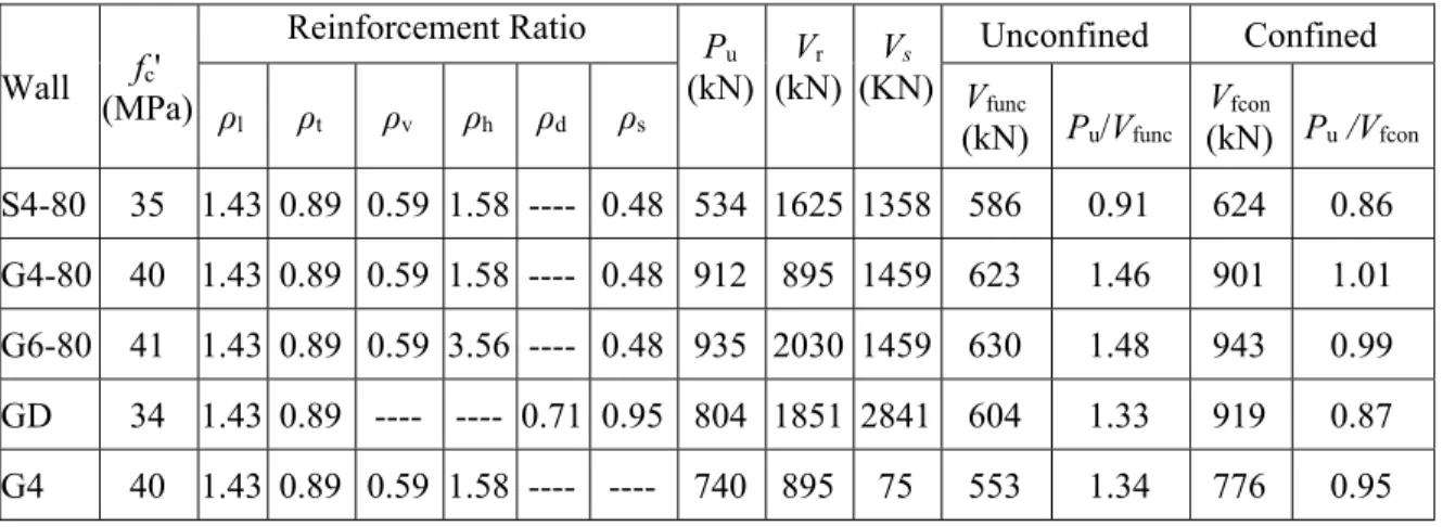
Table 4.1 – Reinforcement details and calculated capacities of the walls 62
Table 4.2 – Reinforcement mechanical properties 63
Table 4.3 – Wall failure progression 73
Table 5.1 – Concrete strength and reinforcement details 91
Table 5.2 – Summary of the test results 95
Table 5.3 – Ultimate strength prediction 117
Table 5.4 – Evaluation of the confinement effect 119
Table 6.1 – Tensile properties of the reinforcement 126
LIST OF FIGURES
Figure 1.1 – Corrosion in squat walls 2
Figure 2.1 - Structural walls’ categories based on height to length ratio 8
Figure 2.2 - Squat wall applications 9
Figure 2.3 – Diagonal tension failure; (a) schematic details; (b) photo (Woods et al. 2015) 10
Figure 2.4 – Diagonal compression failure 11
Figure 2.5 – Sliding shear failure; (a) schematic detail; (b) Photo (Paulay et al. 1982) 12 Figure 2.6 – Load transfer in squat walls (Barda et al. 1977) 13
Figure 2.7 – Typical Shapes of Squat Walls 14
Figure 2.8 – Shear resistance mechanisms in squat walls (Paulay 1972) 18
Figure 2.9 – Sliding shear resistance components 22
Figure 2.10 – Pultrusion process 28
Figure 2.11 – Stress strain for steel and FRP bars 29
Figure 2.12 – Bends in GFRP bars reinforcement 32
Figure 2.13 – Effect of the lengthening of period on design force levels 34 Figure 2.14 – Measured shear strain at ultimate load (Mohamed et al. 2014b) 38
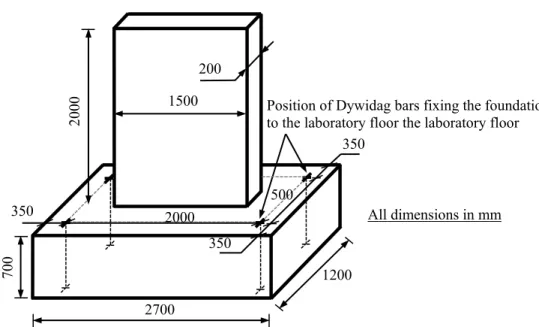
Figure 3.1 – Overall dimensions of test walls 40
Figure 3.2 – Reinforcement details 42
Figure 3.2 – Reinforcement details (continue) 43
Figure 3.3 – GFRP reinforcement 45
Figure 3.4 – Prepared formwork and cage of the base 45
Figure 3.5 – Assembly of the wall cage to the base cage 46
Figure 3.6 – Assembly and alignment of wall formwork 46
Figure 3.7– Casting the base 46
Figure 3.8 – Casting the wall 46
Figure 3.9 – Specimens after curing 46
Figure 3.10 – Test-setup 52
Figure 3.11– Loading history of testing program 53
Figure 3.12 – Stain gauges instrumentation 54
Figure 3.13 – LVDTs instrumentation 55
Figure 4.1 – Concrete dimensions and reinforcement details 60
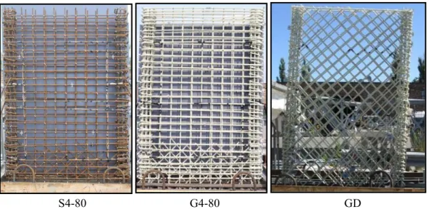
Figure 4.2 – GFRP reinforcement and wall cage 63
Figure 4.3 – Test setup 68
Figure 4.4 – Loading history 68
Figure 4.5 – Instrumentation 69
Figure 4.6 – Crack pattern 70
Figure 4.7 – Failure progression of specimen S4-80 71
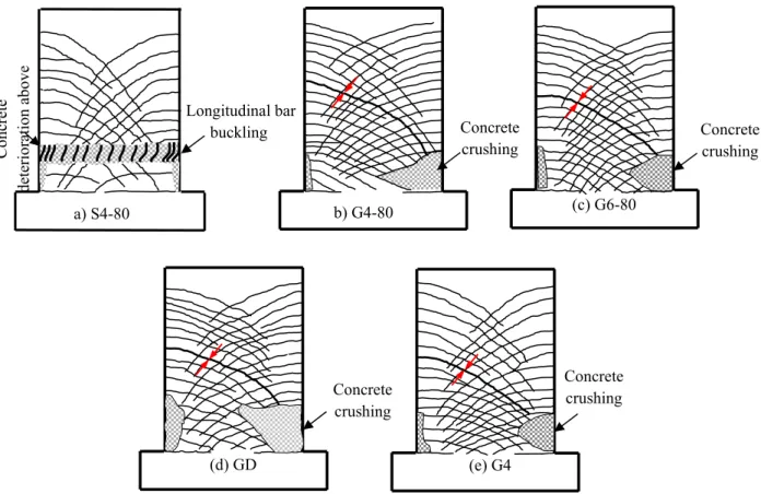
Figure 4.8 – Failure progression of specimens G4-80, G6-80, and G4 72
Figure 4.9 – Failure of specimen GD 72
x List of Figures
Figure 4.11 – Envelope curves: Steel vs. GFRP 78
Figure 4.12 – Envelope curves: Top displacement 80
Figure 4.13 – Concrete strain 82
Figure 4.14 – Energy dissipation 84
Figure 5.1 – Concrete dimensions and details of reinforcement 90
Figure 5.2 – Test Setup 93
Figure 5.3 – Displacement history 93
Figure 5.4 – Instrumentation: (a) LVDTs instrumentation; (b) strain-gauge instrumentation 94
Figure 5.5 – Crack pattern 96
Figure 5.6 – Lateral load versus top displacement 97
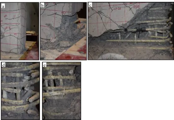
Figure 5.7 – Failure modes: (a) G4-250; (b) G4-160; (c) G4-80; (d) G6-80; (e) G-V; (f) G-H 99
Figure 5.8 – Damage aspects 99
Figure 5.9 – Load-top displacement envelope curves 102
Figure 5.10 – Vertical strains distribution along the wall length 103
Figure 5.11 – Maximum measured vertical strain 105
Figure 5.12 – Horizontal strain distribution along the wall height 106 Figure 5.13 – Load-average horizontal strain envelope curves 107
Figure 5.14 – Load-shear crack width envelope curves 108
Figure 5.15 – Vertical strain versus horizontal strain at the same location (G4-250) 108 Figure 5.16 – Maximum measured horizontal strain versus shear crack width 109 Figure 5.17 – (a) Concrete shear strength versus top displacement envelope curves; (b) shear
resistance components 111
Figure 6.1 – Concrete dimensions, reinforcement details, test setup, load history, and
instrumentation 126
Figure 6.2 – Failure modes of the test specimens 127
Figure 6.3 – Load–top-displacement envelope curves 128
Figure 6.4 – Decoupling of flexural and shear deformations 129 Figure 6.5 – Method for estimating α (rotation profile over the wall height) 130 Figure 6.6 – Calculated curvature and rotation profiles for the test specimens 130 Figure 6.7 – Comparison between the measured and calculated displacement at a height
equal to the wall length 132
Figure 6.8 – Displacement components at a height equal to the wall length 133 Figure 6.9 – Comparison between flexural and shear deformations in test specimens 134 Figure 6.10 – Truss model for shear deformation estimation 136 Figure 6.11 – Lateral load versus experimental and predicted shear deformations using
different shear crack angles 139
Figure 6.12 – Lateral load versus experimental and predicted shear deformations using
different concrete shear strength (θ = 60o) 140
Figure 6.13 – Concrete shear strength versus top displacement 141 Figure 6.14 – Shear stiffness degradation normalized with gross shear stiffness versus drift
ratio 141
Figure 6.15 – Validation of the proposed model for shear stiffness degradation 143 Figure 6.16 – Comparison of predicted normalized shear stiffness with experimental data 144
Figure 6.17 – Comparison of Predicted (a) flexural displacement (b) normalized flexural stiffness 147 Figure 6.18 – Normalized flexural stiffness versus drift ratio 148
CHAPTER 1
INTRODUCTION
1.1. General Background
Squat walls are defined as structural walls with a height to length ratio (aspect ratio) less than 2.0. This type of wall is widely used as the primary seismic-force resisting component in low-rise structures such as nuclear facilities, industrial buildings, and parking structures. Moreover, such walls also frequently serve as bridge piers and abutments. Squat walls may also be used in high-rise buildings where a substantial part of the lateral load may be assigned to them when extending over the first few stories above foundation level (Paulay et al. 1982).
Because of their aspect ratio, squat walls—unlike slender walls—generate high shear forces at their bases to develop structural flexural strength, which makes shear capacity a major issue in their design (Paulay et al. 1982; Kuang and Ho 2008; Whyte and Stojadinovic 2014). Investigations revealed that the flexural and shear deformations are intimately correlated in squat walls. By the onset of flexural reinforcement yielding, shear deformations either shear distortion and/or sliding have been shown to be activated and localized along the yielding zone then begins to dominate the behavior causing rapid degradation in strength and stiffness with subsequent premature shear failure (Paulay et al. 1982; Saatcioglu 1991; Sittipunt et al. 2001). In North America, many bridges and other types of buildings in which squat walls are used are deficient due to the corrosion of steel reinforcement and consequent failure in concrete (Figure 1.1). Some conditions, such as, significant temperature fluctuations and environmental aggression aggravate this phenomenon and make the hazard more severe.
The high economic consequences of corrosion problems led engineers all over the world to search for new and affordable construction materials as well as innovative approaches and systems to problem solving. In recent years, the use of fiber-reinforced polymer (FRP) as an alternative reinforcing material in concrete structures has emerged as an innovative solution to overcome the corrosion problem. In addition to its non-corrodible nature, FRP reinforcement
2 Chapter 1: Introduction presents many advantages such as high strength-to-weight ratio, ease of handling, and immunity against the electrochemical corrosion (Rizkalla et al. 2003, Benmokrane et al. 2006, 2007). These advantages paved the way for their applications into numerous construction elements such as slabs, beams, columns (Arafa et al. 2016a, El-Salakawy et al. 2005, Kassem et al. 2011, Tobbi et al. 2012). However, since the investigations mainly focused on the behavior under static-loading conditions omitting the seismic design; the feasibility of using FRP as internal reinforcement for a complete structure immune to corrosion while having strength, stiffness, and deformation capacity to resist seismic loads, has become questionable.
Figure 1.1 – Corrosion in squat walls
To address this issue, an experimental study was conducted by Mohamed et al. (2014a) to investigate the behavior of mid-rise shear walls totally reinforced with glass (G) FRP bars. Four large-scale shear walls—one reinforced with steel bars (as reference specimen) and three totally reinforced with GFRP bars—were constructed and tested to failure under quasi-static reversed cyclic lateral loading. The reported test results clearly showed that properly designed and detailed GFRP-reinforced concrete (RC) walls could reach their flexural capacities with no strength degradation while achieving high level of deformability. The test results also revealed the potential of GFRP bars in controlling shear distortion compared to steel reinforcement (Mohamed et al. 2014b). It was explained that using elastic material (GFRP bars) gave uniform distribution of shear strain along the shear region of GFRP RC shear walls, resulting in a better control of shear distortion compared to steel RC shear wall, in which the yielding of the flexural reinforcement redistributed shear strains causing their localization at the yielding zone.
3 The conducted results of using FRP bars in mid-rise shear walls in term of its ability in controlling shear distortion and overriding the corrosion problem called for a new investigation to study the feasibility of using this material in squat walls in which these problems are frequently encountered. Currently; however, no experimental data are available on the seismic behavior of squat walls reinforced with FRP reinforcing bars. This has been the main impetus to carry out this study to fill the gap of knowledge and provide information about this behavior.
1.2. Objectives and Scope
Experimental program on large-scale squat walls reinforced with GFRP bars under reversed cyclic lateral loading was conducted. The ability of such structural element to achieve the strength and drift requirements, specified in various codes, is the main scope of this study. Basically, the objectives of the current study can be summarized as follows:
1. Investigate the difference in behavior between GFRP and steel RC walls;
2. Assess the influence of bidiagonal web reinforcement in lieu of horizontal and vertical web reinforcement on the shear strength of squat walls;
3. Study the efficiency of bidiagonal sliding reinforcement to suppress sliding failure; 4. Examine the effect of web reinforcement configuration (horizontal and/or vertical) and
ratio;
5. Assess methods to reasonably predict the ultimate flexural and shear strength;
6. Assess methods to calculate realistic flexural and shear deformations in squat walls; and
7. Evaluate the walls’ flexural and shear stiffness.
1.3. Methodology
To achieve the foregoing objectives, a series of test specimens that comprised nine large-scale squat walls were constructed and tested laterally under quasi-static reversed cyclic loading up
4 Chapter 1: Introduction to failure. One wall was reinforced totally with steel bars and served as a control specimen while the others were reinforced with GFRP bars in different configurations and reinforcement ratios according to the studied parameters. The preliminary design and reinforcement details of the wall specimens were conducted according to the CSA A23.3 (2014) for steel RC wall and the CSA S806 (2012) for GFRP RC walls. Given the absence of seismic provisions in the CSA S806 (2012); however, similar philosophies that are being used in the companion code, CSA A23.3 (2014), were adopted. Analysis of the experimental results in term of deformability, energy dissipation, ultimate strength, and failure mode was conducted showing the main aspects of difference between the behavior of steel and GFRP RC squat walls. Evaluation of the influence of either bidiagonal web reinforcement or sliding reinforcement was discussed. The experimental results were also analyzed, identifying the effect of different web reinforcement configurations and ratio on the crack pattern and failure mode, drift capacity and ultimate strength as well as the shear crack widths. Documentation of the strain distribution in either horizontal or vertical direction was also presented. Evaluation of the ultimate capacity according to the ACI and CSA codes provisions was also introduced. As a result, some recommendations that assist in a reasonable estimation of the ultimate strength were given.
The experimental measurements permitted to decouple flexural and shear deformations and examine their contribution to the lateral deformations. The results showed that shear deformation significantly increase by the onset of the first shear crack initiation and represented a significant portion of the total deformations. Consequently, prediction of shear stiffness of squat walls beside its flexural stiffness was found to be necessary. The available expressions in guidelines and codes as well as some technical papers were used in lateral shear and flexural stiffness prediction. Additionally, in the context of displacement based design, a simple model that directly correlates the flexural and shear stiffness degradation of the tested walls to their top lateral drift was proposed.
1.4. Thesis Organization
The thesis consists of seven chapters. The contents of each chapter can be summarized as follows:
5 Chapter 1 of this thesis presents background information on the research topic, the work objectives and the adopted methodology.
Chapter 2 introduces a literature review reporting the past known characteristics of steel RC squat walls. Some aspects such as failure modes and the most decisive parameters that affect the walls’ behavior are presented. Additionally, the available methods in the ACI 318 (2014) and CSA A23.3 (2014) for ultimate shear strength’s prediction are introduced. This is followed by a background about some mechanical characteristics of FRP reinforcement. Finally, the available knowledge of seismic behavior of FRP RC systems is discussed.
Chapter 3: gives the details of the experimental program and the testing procedure. The geometry and reinforcement details of the test specimens, web reinforcement configuration, test setup and procedure, and the instrumentation details are presented. In addition, detailed characteristics of the used materials are provided.
The subsequent three chapters respectively correspond to three technical papers and one technical note that have submitted for publication in scientific journals:
Chapter 4: (Paper 1) Arafa, A., Farghaly, A. S., and Benmokrane, B., 2016 (submitted) “Experimental Behavior of GFRP-Reinforced Concrete Squat Walls subjected to Simulated Earthquake Load,” Journal of Composites for Construction, ASCE. Chapter 5: (Paper 2) Arafa, A., Farghaly, A. S., and Benmokrane, B., 2017 (submitted)
“Effect of Web Reinforcement on the Seismic Response of Concrete Squat Walls Reinforced with Glass-FRP Bars,” Engineering Structures.
(Paper 3) Arafa, A., Farghaly, A. S., and Benmokrane, B., 2017 (submitted technical note) “Prediction of Flexure and Shear Strength of Concrete Squat Walls Reinforced with Glass-FRP Bars,” Journal of Composites for Construction, ASCE.
Chapter 6: (Paper 4) Arafa, A., Farghaly, A. S., and Benmokrane, B., 2017 (submitted) “Evaluation of Flexural and Shear Stiffness of Concrete Squat Walls Reinforced with Glass-Fiber-Reinforced-Polymer (GFRP) Bars,” ACI Structural Journal.
6 Chapter 1: Introduction Chapter 7 presents a general conclusion of the results obtained from the experiments and analyses with respect to the problems and observations discussed throughout the thesis in addition to recommendations for future work.
7
CHAPTER 2
LITERATURE REVIEW
2.1. Introduction
In this chapter, a survey of relevant previous works related to this research study is presented. A review for the behavior of steel RC squat walls under seismic loading is first presented. Emphasis is given on the identifications of failure modes and main factors that affect the behavior. In addition, a summary of the available models in the ACI 318 (2014) and CSA A23.3 (2014) that are being used in predicting the ultimate shear strength of steel RC walls is presented. This is followed by a brief summary about FRP material constituents, manufacturing, and properties as well as the available knowledge of seismic behavior of FRP RC systems.
2.2. Steel RC Squat Walls
2.2.1. General Background
Reinforced concrete walls are commonly used as the primary component for lateral load-resisting system in buildings prone to seismic risk and/or wind pressure. Compared to frame-type structures, the main advantages that can be rendered by structural walls are the significant increase in building’s lateral stiffness which leads to a reduction of second-order effects and subsequent increase of safety against collapse (Fintel 1995, Paulay 1972). Even after extensive cracking, the structural walls are able to maintain most of their vertical load-bearing capacity which is not always the case for frame-type systems. These advantages were recognized and evidenced from the observation during the 3 March 1985 Chilean earthquake (Wyllie et al. 1986); where buildings equipped with well-designed RC walls showed overwhelming success in controlling damages.
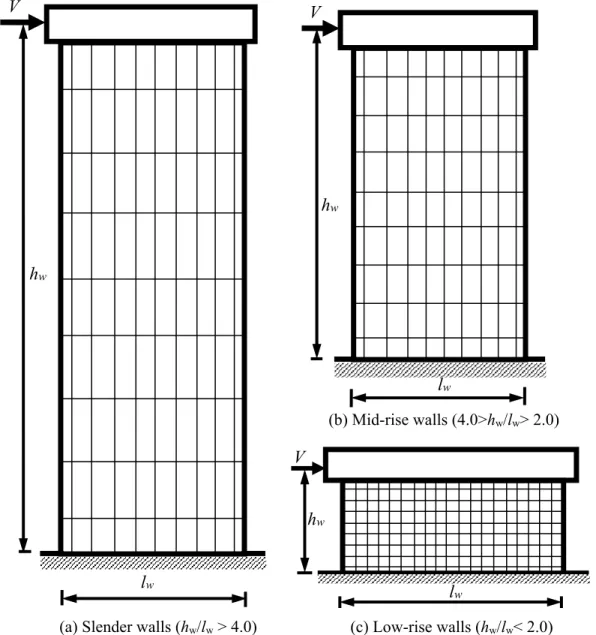
Structural walls are generally classified based on its height to length ratio into three categories; slender walls, mid-rise walls, and squat walls. Slender walls are structural walls with a height
8 Chapter 2: Literature Review to length ratio larger than 4.0. Such type of walls is used in high rise buildings and it can be treated as ordinary reinforced concrete cantilever beam. In slender walls, it is relatively easy to ensure developing adequate ductility as flexural behavior is dominated. Structural walls with a height to length ratio between 2.0 and 4.0 are classified as mid-rise walls and widely used in mid-rise buildings (buildings with 4 to 10 stories). Both nonlinear flexural and shear deformations significantly contribute to the lateral response of such shear walls. The last category is squat walls with a low height to length ratio that is typically less than 2.0.
Figure 2.1 - Structural walls’ categories based on height to length ratio (a) Slender walls (hw/lw > 4.0) (c) Low-rise walls (hw/lw< 2.0)
(b) Mid-rise walls (4.0>hw/lw> 2.0) V hw lw V hw lw lw V hw
9 Squat walls are widely used in low-rise buildings such as nuclear plants, industrial buildings; parking structures, highway overpasses, and bridge abutments (Figure 2.2 shows some applications of using squat walls). Squat walls may also be used in high-rise buildings where a significant portion of lateral load can be assigned to them (Paulay et al. 1982).
Figure 2.2 - Squat wall applications; (a) wall in nuclear reactor (Whyte and Stojadinovic. 2013), (b) bridge piers, (c) overpass piers, (d) bridge abutment, (e) low-rise housing made
of walls and slabs (Sánchez-Alejandre and Alcocer 2010)
In squat walls, relatively large shearing forces are generated at the wall base, that are sufficient to destroy the structure in brittle shear manner before achieving its flexural strength. This is mainly due to the combination of a squat (low height to length ratio) and the uniform distribution of vertical reinforcement across the wall’ section. Therefore, squat wall behavior is generally dominated by shear deformations (shear distortion and/or sliding shear deformations) and its shear capacity constitutes a major concern in their design. Numerous experimental and analytical investigations have been devoted to study the behavior of steel RC squat walls under quasi-static reversed cyclic lateral loading as a simulation for seismic loading. Based on these studies; failure modes, hysteretic behavior characteristics as well as the main parameters affecting the behavior and ultimate shear strength were identified. These
(e)
(a) (b) (c)
10 Chapter 2: Literature Review issues will be discussed in the following subsections in addition to the codes’ methods for ultimate shear strength estimation.
2.2.2. Mode of Failures
2.2.2.1. Diagonal Tension Failure
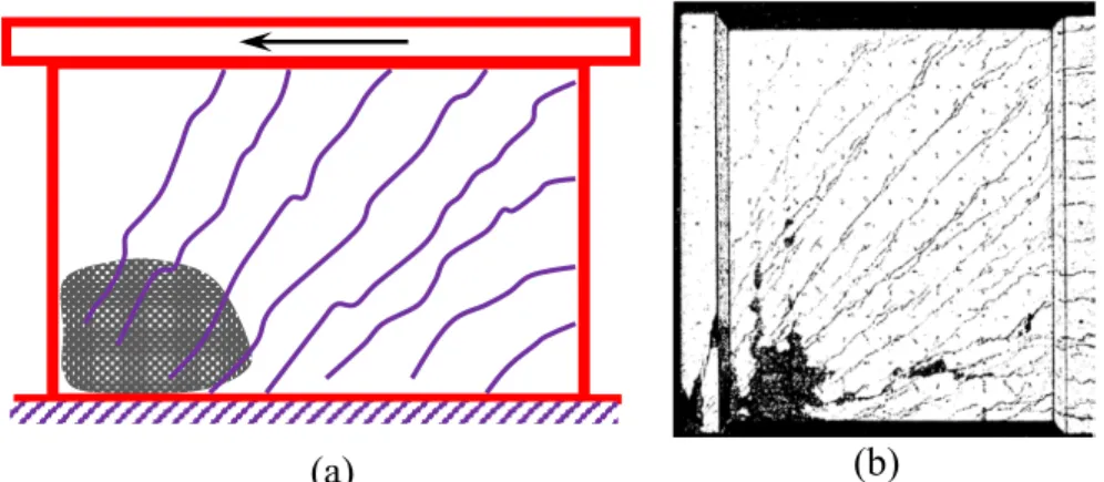
Failure due to diagonal tension occurs when horizontal web reinforcement is inadequate (Figure 2.3a). In such case, horizontal reinforcement yields and widely spaced diagonal cracks appear. The failure then occurs suddenly through a sliding along diagonal plane associated with the rupture of the horizontal reinforcement crossing this plane as shown in Figure 2.3b. Test results demonstrated that the inclination of failure plane can be affected by the wall’s aspect ratio (height to length ratio) and the existence of a beam at the top of the wall (Paulay et al. 1982). The results also showed that avoiding such types of failure can be achieved by providing horizontal shear reinforcement capable of transferring a larger shear force than the one which produces flexural yielding.
Figure 2.3 – Diagonal tension failure; (a) schematic details; (b) photo (Woods et al. 2015)
2.2.2.2. Diagonal Compression Failure
If adequate horizontal shear reinforcement is provided and the average shear stress in the wall section is large, concrete may crush under diagonal compression. Resistance of the concrete compression struts in the web of the wall deteriorates as the inclined cracks in two opposite directions open and close successively under cyclic loading. Ultimately, the concrete struts are crushed as shown in Figure 2.4a. This type of failure mode occurs for walls with a very high shear stress such as walls with flanges or barbells and/or walls with a high axial load. Flanged and barbell walls can potentially accommodate more reinforcement at the wall ends, which
(b)
Horizontal bars rupture
11 provides substantial flexural strength and increase the shear demands in the wall web. In spite of the preferable effect of axial load in term of controlling shear crack width and increasing the shear strength; their existence with large value increase the compressive stresses in the web of the wall and accelerate the occurrence of diagonal compression failure. Diagonal compression failure is usually associated with dramatic and irrecoverable loss of strength. Therefore, diagonal compression failure is highly undesirable (Paulay et al. 1982). This mode of failure can only be avoided if the average shear stress in the wall critical section is limited between 0.5 fc1/2and 0.9 fc1/2; as a function of the ductility requirements imposed on the wall (Park and Paulay 1975, Oesterle et al. 1980). An example of a diagonal compression failure from Maier and Thürlimann (1985) is shown in Figure 2.4b.
Figure 2.4 – Diagonal compression failure; (a) schematic detail; photo (Maier and Thürlimann 1985)
2.2.2.3. Sliding Shear Failure
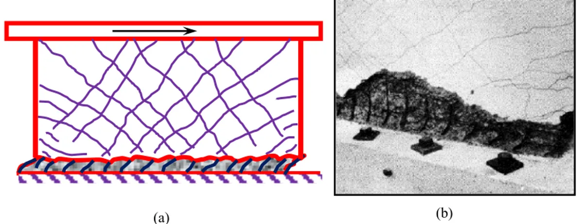
Sliding shear failure occurs when the wall has sufficient horizontal reinforcement to prevent a diagonal tension failure, and relatively small amount of vertical reinforcement in the wall web with low axial loading. Inelastic deformation required for energy dissipation would be expected to be created mainly from post yielding strains originated in the vertical flexural reinforcement. However, after a few cycles of reversed loading that causes significant yielding in the flexural reinforcement, sliding displacement can occur along flexural cracks that interconnect and form a continuous horizontal shear path, as depicted in Figure 2.5a. Such sliding displacements are responsible for a significant reduction of stiffness, particularly at
(b) (a)
12 Chapter 2: Literature Review low load intensities, consequently, a reduction of energy dissipation (Paulay et al. 1982). This mode of failure is also responsible for significant degradation of stiffness. Typical sliding shear failure reported by Paulay et al. (1982) is shown in Figure 2.5b.
Figure 2.5 – Sliding shear failure; (a) schematic detail; (b) Photo (Paulay et al. 1982)
2.2.3. Factors Affecting Squat Walls Behavior
The experimental database compiled from previous experimental and analytical researches revealed that the shear behavior of squat wall was governed by many factors such as wall’s aspect ratios, presence of boundary elements (barbells or flanges), horizontal and vertical web reinforcement, diagonal web reinforcement, construction joint as well as the magnitude of axial loading. Summary about the effect of each parameter is briefly presented in the following subsections.
2.2.3.1. Wall’s Aspect Ratio
There is an agreement that aspect ratio (height to length ratio) is one of the most crucial parameters that affects the shear strength, deformability and mode of failure of squat walls. The work conducted by Barda et al. (1977) is one of the early investigations that studied this parameter. Eight flanged squat walls with aspect ratios of 0.25, 0.5, and 1.0 were constructed and tested under lateral loading. It was observed that walls with lower aspect ratio possess high shear strength; the shear strength of specimen with aspect ratio of 0.5 was found to be 20% higher than the shear strength of the companion specimen with aspect ratio of 1.0. This
13 increase can be explained based on load transfer mechanism which was reported by the authors. Barda et al. (1977) reported that a significant amount of shear transmitted in squat walls from the top slab to the foundation by the so-called lattice action (arch action). This mechanism consists of the vertical wall reinforcement acting in tension (tie) and concrete struts in the wall between inclined cracks acting in compression (Figure 2.6). One of the most crucial parameter that influences the strut efficiency is the angle between strut and tie; the strut will lose its capacity as it approaches the direction of the tie. Since this angle is higher in low aspect ratio; it is therefore the walls with low aspect ratios that have higher peak shear strength compared to taller walls with similar properties. The increase of shear strength with lower aspect ratio was also documented by Gulec and Whittaker (2009) based on statistical study including the results of 434 test results of squat walls subjected to lateral load. The effect of aspect ratio on the shear strength has also been considered by most of the available models for shear strength estimations of squat walls; for example, Barda et al. (1977); Hwang et al. (2001); Gulec and Whittaker (2009); and Kassem (2015). Nevertheless; contradiction regarding the effect of aspect ratio is still found between the ACI 318 (2014) and CSA A23.3 (2014) methods for shear strength prediction. Whereas; the aspect ratio effect is introduced within the concrete shear contribution term in the ACI 318 (2014), the CSA A23.3 (2004) does not account for this parameter in shear strength estimations.
Figure 2.6 – Load transfer in squat walls (Barda et al. 1977)
In addition to their influence on shear strength, lower aspect ratio was also found to result in stiffer structures with lower deformability. These remarks were evidenced from the behavior
Vertical Reinforcement Concrete Strut Vu hw lw Concrete Strut
14 Chapter 2: Literature Review of 26 squat walls with aspect ratios ranged from 0.7 to 2.0 (Hidalgo et al. 2002). Other test results also indicated that walls with a low aspect ratio may be more vulnerable to sliding shear than those with a higher aspect ratio as reported by Salonikios et al. (1999 and 2000). 2.2.3.2. Presence of Boundary Elements
Squat walls are generally grouped by plan geometry into rectangular walls or walls framed by either end boundary columns (barbell walls) or boundary flanges (flanged walls) (Figure 2.7). Boundary elements are often presented to allow effective anchorage of transverse beams. Even without beams, they are often provided to accommodate the principal flexural reinforcement, to provide stability against lateral buckling of a thin-walled section and to provide more effective confinement of the compressed concrete in the potential plastic hinge. Walls meeting each other at right angles will give rise to flanged sections. Such walls are normally required to resist earthquake forces in both principal directions of the building.
Figure 2.7 – Typical Shapes of Squat Walls
A review of the literature revealed that most previous studies on squat walls mainly focused on a single shape; hence the effect of this parameter on squat walls behavior could only be estimated by comparing results for similar walls tested in different programs. More specifically, only the works conducted by Paulay et al. (1982) and Maier and Thurlimann (1985) have two types of wall shapes; rectangular, and flanged. Paulay et al. (1982) reported that flanged walls are more seriously affected by sliding shear along interconnecting flexural cracks. Maier and Thurlimann (1985), on the other hand, reported that the horizontal
15 resistance is a function of the cross-sectional geometry; adding boundary elements improve the strength of squat walls. The concept of comparing results for similar walls tested in different programs with the objective of estimating the crucial parameters and validating some proposed analytical models in squat walls was followed by some researchers (Hwang et al. 2001, Gulec and Whittaker 2009; Kassem 2015).
Hwang et al. (2001) reviewed and catalogued the results of 62 reinforced concrete squat walls with different shapes with the aim of calibrating a proposed softened strut and tie model for the determination of shear strength of squat walls. The investigation showed that walls with barbell or flanged cross-section resist significantly higher shear forces than a rectangular wall with the same amount and arrangement of web reinforcement. Some flanged walls achieved 20% higher shear strength than other identical rectangular walls. The authors explained that the higher capacity of flanged walls can be attributed to the improved end conditions of its diagonal strut provided by the compression boundary element. The authors added that the depth of compression strut of a wall increases with the presence of boundary elements which leads to an increase in the shear strength. The same conclusions were drawn by Gulec and Whittaker (2009) and Kassem (2015) based on a database of information from tests of 434 and 645 squat walls, respectively. Kassem (2015); however, added that the existence of boundary elements cause additional confining effect which reduces the concrete softening effect and limits the cracking and extension of the walls; subsequently, increasing in the shear capacity. Even though the review emphasized on the effectiveness of boundary elements in enhancing squat wall’s shear strength; current ACI 318 (2014) and CSA A23.3 (2014) ignore the cross-section effect on shear strength predictions; resulting in less-than-satisfactory estimates with a disagreement with the experimentally observed structural behavior. This remark with other deficiencies has been reported by many researchers (for example, Hwang et al. 2001, Gulec and Whittaker 2009, Kassem 2015) who pointed to the importance of developing more rational prediction methods capable of fully characterizing the real response of RC squat walls under various loading conditions while considering those parameters that significantly influence the behavior of such walls.
16 Chapter 2: Literature Review 2.2.3.3. Horizontal and Vertical Web Reinforcement
Previous investigations on steel RC squat walls have confirmed that minimum horizontal and vertical web reinforcement are essential for crack control. Nevertheless, there is no consensus between researchers about the effect of horizontal and vertical web reinforcement on the shear strength. Some researchers reported that using proper amount of horizontal reinforcement suppresses the diagonal tension, hence increasing in the shear and deformation capacity of squat walls (Paulay et al. 1982; Pilakoutas and Elnashai 1995; Hidalgo et al. 2001). In contrast to what adopted by those researchers, other experiments showed that horizontal web reinforcement has no impact on the shear strength of squat walls, whereas, it significantly increases as a function of vertical web reinforcement (Maier and Thurlimann 1985; Wood 1990; Lefas et al. 1990; Gupta and Rangan 1996; Emamy Farvashany et al. 2008). In between the first and second opinion, other investigations; however, indicated that the presence of both horizontal and vertical web reinforcement activate more contribution of concrete for shear resistance mechanism by providing additional load paths beside the diagonal strut, and hence increase the shear capacity (Cardenas et al. 1980, Hwang et al. 2001, Kassem 2015).
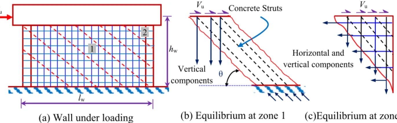
Current ACI 318 (2014) and CSA A23.3 (2014) methods for shear strength estimation of squat walls only account for the amount of horizontal web reinforcement. Nevertheless, both codes recognized that vertical web reinforcement is essential to maintain equilibrium of internal forces. Considering the Barada et al. (1972) conclusion that for squat walls having aspect ratio less than 1.0, the shear forces are transmitted to the base by inclined struts developed within the web (Figure 2.8a), the inclined struts forces must be vertically in equilibrium by vertical web reinforcement (Figure 2.8b), while both horizontal and vertical web reinforcement contribute in equilibrium at the wall edges (Figure 2.8c) (refer to Paulay 1972). The vertical web reinforcement is therefore recommended by both the ACI 318 (2014) and CSA A23.3 (2014) to be a ratio of the horizontal web reinforcement. Apparently from Figure 2.8c, the ratio that satisfies equilibrium is typically equal to cot2 θ; where θ is the struts inclination angle to the longitudinal axis. The ACI 318 (2014) conservatively assume that θ = 45°; hence, it is required that the vertical web reinforcement should be equal to the horizontal web reinforcement for all squat walls; regardless their aspect ratio. The CSA A23.3 (2014); however, provide Eq. 2.1, to calculate θ that is based on the modified compression field theory
17 and is a function of the wall depth, reinforcement axial rigidity, and internal forces applied at the section of interest.
l
297000 (2.1) where εl = average longitudinal strain at mid-height of the section of interest and can be calculated as follows: F F f v f l A E V d M 2 (2.2)
where Mf, Vf , are the applied moment and shear at the section of interest, dv is the effective shear depth, EF and AF are the modulus of elasticity and the total cross-sectional area of the longitudinal reinforcement at the same section.
Based on the calculated θ, the CSA A23.3 (2014) gives the following equation to calculate vertical web reinforcement ratio:
g y s s h v A f P cot2 (2.3)
where ρv, ρh are the vertical and horizontal web reinforcement, Ps is the axial load; φs is the material resistance factor fy is the specified yield strength of web reinforcement; and Ag gross area of the wall section.
It can be noticed from Eq. 2.3 that the CSA A23.3 (2014) accounts for another component in forces equilibrium that is the compression stresses applied on the wall. This effect; however, is conservatively ignored in the ACI 318 (2014). Furthermore, whereas the ACI required that vertical web reinforcement must equal horizontal web reinforcement regardless their aspect ratio, the CSA A23.3 (2014) limits Eq. 2.3 application for squat walls having an aspect ratio less than 1.0. In spite of the aforementioned discrepancy between the ACI 318 (2014) and CSA A23.3 (2014), both codes agree that minimum horizontal and vertical web reinforcement (equal to 0.25%) should be provided to control cracks propagation and width.
18 Chapter 2: Literature Review
Figure 2.8 – Shear resistance mechanisms in squat walls (Paulay 1972) 2.2.3.4. Use Diagonal Web Reinforcement
Extensive researches have been devoted to study the influence of using diagonal reinforcement; either concentrated at the base to reduce the excessive sliding, or distributed in the web to control shear distortion. Consistent results about this effect have been drawn. Using diagonal reinforcement was found to considerably improve the seismic response of squat walls compared to that with conventional web reinforcement (horizontal and vertical). The aspects of enhancement included preventing sliding shear and diagonal compression failure, reduction in shear distortion and relatively high energy dissipation. In spite of the merits of using diagonal reinforcement, it may attribute higher cost than using horizontal and vertical bars. Given the fact that the diagonal reinforcement needs more labor time to be cut in different lengths as well as the difficulty in their placing and anchorage relatively to using horizontal and vertical reinforcement.
Historically, the first attempt for applying diagonal reinforcement in squat-walls was conducted by Iliya and Bertero (1980). Two walls with aspect ratio of 1.3 were constructed; the first specimen was reinforced with equal amount of horizontal and vertical web reinforcement, while the web reinforcement in the other specimen was arranged diagonally with angle of 45°. The specimens were cyclically loaded up to the first yield of the longitudinal steel in the boundary elements. The cracks in the specimens were then repaired by epoxy grouting. The repaired specimens were subsequently loaded, with a few intermediate cycles, up to failure. Finally, the damaged walls were retrofitted and again subjected to cyclic loadings until failure. The test results showed that the 45° arrangement of the wall reinforcing
(a) Wall under loading (b) Equilibrium at zone 1 (c)Equilibrium at zone 2
Vu hw lw 2 1 Horizontal and vertical components Vu Vertical components Vu Concrete Struts θ
19 bars is more effective in resisting the effect of shear reversals; the specimen with diagonal reinforcement exhibited less stiffness and strength degradation under the cyclic load. In addition, the noticed failure in conventionally reinforced specimens was mainly due to diagonal cracking, whereas in the specimen with diagonal web reinforcement the flexural failure was dominant.
In order to suppress the detrimental effect of sliding shear failure at the base of squat walls, special bidiagonal reinforcement extending from the base through the web was provided in two squat walls tested by Paulay et al. (1982). These walls duplicated two other conventionally reinforced walls with equal flexural and shear strengths. It was concluded that bidiagonal reinforcement considerably improve seismic response of squat walls, even when as little as 30 percent of the applied shear was resisted by such reinforcement. Diagonal reinforcement used in these tests was insufficient to prevent slip. However, when the diagonal bars were yielding due to slip displacements, significant energy dissipation additional to that due to flexure resulted.
Salonikios et al. (1999) carried out a comprehensive experimental program involving eleven wall specimens; six with aspect ratio of 1.5 while the others have aspect ratio of 1.0. The wall specimens were reinforced against shear, either conventionally (orthogonal grids of web reinforcement), or conventionally plus bidiagonal bars. Using bi-diagonal reinforcement was found to offer an attractive alternative to current practice from an economic point of view, since for a lower quantity of total web reinforcement an improved seismic performance was achieved. The authors also reported that the using bidiagonal bars contributed to better control of the inclined shear cracks width in the web of specimen. The main reason for enhancement is that bidiagonal bars intersect the inclined shear cracks almost at right angles; hence, they work essentially in direct tension, whereas the bars in the orthogonal grid intersect the shear cracks at 35 to 45° and tend to work primarily as dowels.
Sittipunt and Wood (1995) carried out an analytical study using finite element models to investigate the effect of using diagonal web reinforcement. The study comprised analysis of six walls with varying arrangements of web reinforcement. Conventional web reinforcement (vertical and horizontal web reinforcement) was used in the first specimen. The amount of
20 Chapter 2: Literature Review horizontal web reinforcement in the lower half of the wall is doubled in second wall, and the amount of vertical web reinforcement in the lower half of the wall is tripled in the third wall. Increase of vertical web reinforcement was also tested in the fourth wall but the bars were not anchored in the foundation. The final two arrangements of reinforcement included equal diagonal web reinforcement in the lower portion of the wall (either distributed or concentrated), in addition to vertical and horizontal web reinforcement. The main drawn conclusion was that hysteretic response of squat walls can be significantly improved by controlling the shear distortion near the base. However, the mechanism by which forces are carried in the web of the wall must be changed if the overall force-displacement response is to be changed appreciably. Adding vertical or horizontal web reinforcement did not improve the hysteretic response significantly because forces were still carried across the cracks in the web by dowel action. Therefore, the possibility of web crushing at a given level of deformation was not decreased. When diagonal reinforcement was added in the web, the load-carrying mechanism was changed to direct tension in the reinforcing bars, and the shear distortion was reduced significantly.
Continuing their efforts in studying the effect of diagonal web reinforcement, Sittipunt et al. (2001) tested four squat walls with aspect ratio of 1.6 and incorporating different web reinforcement ratios and configurations. Two walls contained different amount of horizontal and vertical web reinforcement, while the others contained diagonal web reinforcement (45° orientation) with amount equal to the companion specimens which was reinforced conventionally. All specimens were tested under horizontal quasi-static cyclic load up to failure with absence of axial load. The test results confirmed the outcomes obtained from the pre-described analytical investigation. It was reported that the brittle mode of failure due to web crushing could be avoided by using diagonal web reinforcement; both walls with conventional web reinforcement failed due to web crushing. Pinched shapes characterized the hysteresis curves for top displacement and shear distortion near the base. In contrast, the walls with diagonal reinforcement displayed rounded hysteresis curves and failed due to crushing of the boundary elements. It was also concluded that the advantages in performance of specimens reinforced with diagonal reinforcement can offset the difficulties associated with placement of diagonal bars during construction. Other investigations have been conducted later (Chiou et al.
21 2004, Liao et al. 2004, Shaingchin et al. 2007, Zhong et al. 2009) and yielded to similar results.
2.2.3.5. Construction Joint
Construction joints in squat walls, especially for those under low axial load, may dramatically deteriorate under cyclic load and become the weakest link in the chain; leading to sliding shear failure (Doostdar 1994). After a few cycles of reversed loading that causes significant yielding in the flexural reinforcement, sliding displacement can occur along flexural cracks that interconnect and form a continuous, approximately horizontal shear path (Paulay et al. 1982). Such sliding displacements are responsible for a significant reduction of stiffness, particularly at low load intensities, and consequently, a reduction of energy dissipation. Therefore, to ensure structural resistance of squat walls and ensure energy dissipation, sliding shear across a construction joint should be avoided (Paulay et al. 1982; Salonikios et al. 1999, and 2000). This can be achieved through a rational design of the construction joint such that it has a shear capacity larger than the shear capacity of the wall’s web; hence, it will not constitute the weakest link in the load transfer. As mentioned earlier, once sliding movement commences, major horizontal crack spreads through the entire construction joint and start to widen. Thus, any approach that can delay or prevent the widening of this crack will significantly promote the shear resistance along the construction joints. Defining of these approaches; however, requires the knowledge of how shear is transferred in the construction joint. In this regard, a brief summary of publications covering this topic as well as available recommendations that were proposed to prevent sliding shear are presented in the following paragraphs.
In their efforts to explain how shear is transferred along an existing or potential crack in connections (Construction joint in our case), Birkeland and Birkeland (1966) and Mast (1968) proposed that shear could be transfer by what they termed “shear friction” between the rough faces of the cracks. It is assumed in this theory that as the uneven crack faces slide past one another, the projections on the crack faces ride over one another and force the crack faces apart, stretching any reinforcement crossing the crack sufficiently to cause it to yield. The tensile force so developed in the reinforcement is assumed to compress the crack faces together, which results in frictional resistance to sliding along the crack. Mattock et al. (1975)
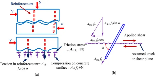
22 Chapter 2: Literature Review experimentally demonstrated the validity of shear friction hypothesis; adding that if a compressive stress is applied to wall section, it should be added to shear resistance component by adding its value to the previously mentioned normal stresses originated by bars crossing the sliding plane. Another investigation by Mattock (1974) showed that when the shear-friction reinforcement is inclined with respect to the shear plane such that the component of the shear force parallel to the reinforcement tends to produce tension in the reinforcement, part of the shear is resisted by the component parallel to the shear plane of the tension force in the reinforcement. Hence; based on the shear friction theory that has proposed by Birkeland and Birkeland (1966) and Mast (1968) and later developed by Mattock (1974 and 1975), the sliding shear resistance can be calculated as the summation of two primary components. The first is the friction caused by all reinforcement crossing the potential sliding shear plane in addition to any normal force acting across it [μ(Avf fy +μN)]; where μ is friction coefficient and depends on the surface roughness; Avf is the area for all reinforcement crossing sliding plane; other terms were previously described) (Figure 2.9a). The second is the component parallel to the shear plane of the tension force in the inclined reinforcement (Ainc fy cos α)(Figure 2.9b).
Figure 2.9 – Sliding shear resistance components
Based on the shear transfer mechanism; Paulay (1972) pointed that if sliding shear failure is desired to be prevented in structural walls, the following aspects should be taken into consideration: Compression on concrete surface =Avf fy +N N Assumed crack or shear plane Applied shear (a) V V Friction stress= μ(Avf fy +N) Tension in reinforcement= Avf fycos α Reinforcement (b) α Ainc fy Ainc fycos Ainc fysin α Ainc fy V
23 1. The construction joint surface should be cleaned and intentionally roughened to use
artificially high values of the coefficient of friction in the shear-friction equations; 2. Any compression force acting across the joint can be utilized in calculation sliding
shear resistance;
3. If the flexural reinforcement that passed through construction joint plus the normal force is not sufficient to resist sliding shear, additional sliding shear reinforcement can be added vertically or diagonally; however, diagonal reinforcement is preferable; and; 4. To preserve the functionality of sliding shear reinforcement, shear-friction
reinforcement shall be appropriately placed along the shear plane and shall be anchored to develop fy on both sides by embedment, hooks, or welding to special devices.
2.2.3.6. Axial Load
Little experimental works have been conducted to assess the effect of axial load on the behavior of reinforced concrete squat walls (Lefas et al. 1990; Salonikios et al. 1999; Li and Xiang 2014). Three levels of constant axial loads were investigated in the testing program by Lefas et al. (1990); 0.0, 0.1, and 0.2 of the axial capacity of the walls; while two levels of axial loading were tested by Salonikios et al. (1999) and Li and Xiang (2014); (0.0, and 0.07), (0.0, and 0.05) of the axial capacity, respectively. It was reported that axial load has a significant effect on enhancing the shear strength and stiffness of the squat walls. This is due to the fact that axial loads significantly control shear cracks width and therefore the ability of structure to transfer shear by the aggregate interlock would be substantial. In addition, axial load was shown to significantly enhance the wall resistance against sliding shear.
In spite of the agreement between the mentioned studies about the beneficial effect of axial loads on squat walls behavior, other researchers (Park and Paulay 1975; Paulay et. 1982) reported that common squat walls generally carry small axial loads, and therefore this effect was suggested to be ignored. The contradiction can be also found between the available analytical models and guidelines methods for predicting the shear strength of squat walls. For instance, the effect of normal force was incorporated in the softened truss model which was proposed by Hsu and Mo (1985) and the softened strut and tie model which proposed by
24 Chapter 2: Literature Review Hwang et al. (2001) and simplified later by Kassem (2015). This effect is also involved in the empirical equations suggested by Gulec and Whittaker (2009). Nevertheless; the ACI 318 (2014) and CSA A23.3 (2004) methods for shear strength estimation of squat walls still ignore this effect.
2.2.4. Ultimate Shear Strength Prediction
To predict the nominal shear strength of squat walls, two procedures are usually followed. The first depends on derivation of empirical equations based on the experimental investigations and test results. In the second procedure, the researchers assume a shear model based on the structure mechanics and conduct a formula for prediction after use equilibrium, compatibility and material constitutive relationships. The current code provisions use empirical or semi-empirical equations to calculate the nominal shear strength of squat walls. In the following subsections, a brief summary of the available equations that predict nominal shear strength of squat walls in the ACI 318-14 and CSA A23.3-14 codes are presented.
ACI 318 (2014)
The current ACI 318 (2014) shear strength expression is based on an assumed shear crack at a 45° angle across an effective wall length (lw), and is comprised of two superimposed resisting mechanisms: the shear reinforcement strength and the concrete shear strength. The contribution of shear reinforcement is estimated by considering equilibrium of forces at a typical joint of the 45о truss model while concrete contribution has been empirically obtained from experimental results. The ACI 318 (2014) expression for in-plane shear resistance (V) of steel RC squat walls is given as follows (SI units):
' ' ) 0.83 ( c c h yh cv c cv f f A f A V (2.4) where αc is the aspect ratio coefficient equal to 0.25 for hw/lw ≤ 1.5, 0.17 for hw/lw ≥ 2.0, and varies linearly between 0.25 and 0.17 for aspect ratios between 1.5 and 2.0, λ is a coefficient depending on the concrete type; equal to 1.0 for normal weight concrete and 0.75 for lightweight concrete, fc’ is the concrete compressive strength, ρh is the horizontal web reinforcement ratio, fyh is the horizontal reinforcement yield stress, and Acv is the gross area of the web of the wall (equal to wall length × web thickness).
25 CSA A.23 (2014)
The CSA A23.3 (2014) provides a shear design method based on the modified compression field theory (MCFT) (Vecchio and Collins 1986). In this theory, the shear resistance of a concrete member can be expressed as the sum of concrete contribution (Vc), which depends on the tensile stresses in concrete, and the shear reinforcement contribution (Vs). However, due to the significant degradation of concrete shear resistance caused by crisscross shear cracks; the CSA A23.3 (2014) ignores the concrete contribution in shear strength. Following this concept, the shear strength of squat walls can be predicted based on the shear capacity of shear reinforcement only which can be calculated as follows (SI Units):
cot s v y v s A f d V s (2.5) where,
s is the material resistance factor (equal 1.0 in case of comparison with experimental),Av is the area of transverse web reinforcement perpendicular to the axis of member with in the distance s, fy is the specified yield strength of web reinforcement, dv is the effective shear depth equal to the greater of 0.9d or 0.72 lw but should not be less than 0.8 lw (Clause 21.6.9.3), θ is the angle of inclination of diagonal compressive stresses to the longitudinal axis of the wall. Unlike the ACI 318 (2014), a rotating crack provision is used in which the angle of the principal compression strut varies depending on the longitudinal strain condition and can be calculated based on the following equations with maximum value of 50 о and minimum value of 30о: x 297000 (2.6) s s f v f x A E V d M 2 / (2.7)
2.3. FRP Composite Materials
The deterioration of reinforced concrete structures due to steel corrosion has become a serious problem in the last decades. In North America, this phenomenon has been accelerated in many