Development of durable, ecologic and corrosion resistant
non-chromate coatings for aluminum
Par Redouane Farid
Thèse présentée à l’Université du Québec à Chicoutimi en vue de l’obtention du grade de doctorat en ingénierie
Québec, Canada
ii
Development of durable, ecologic and corrosion resistant
non-chromate coatings for aluminum
Ph.D. Thesis Redouane Farid
University of Quebec At Chicoutimi
Jury
Dr. Dilip Kumar Sarkar (Director) University of Quebec At Chicoutimi
Dr. Saleema Noormohammed (Examiner) National Research Council of Canada, Saguenay
Dr. Raghavan Subasri (Examiner) International Advanced Research Centre for Powder Metallurgy and New Materials (ARCI)
Dr. Zhan Zhang (Examiner) University of Quebec At Chicoutimi
iii
iv
RÉSUMÉ
Le présent travail fournit un aperçu sur le développement d’alternatives écologiques aux revêtements à base de chrome pour la protection de l’aluminium contre la corrosion. Des films minces de silicate de sodium, de silicate de zirconium et de stéarate de zirconium ont été fabriqués sur des surfaces en alliage de l’aluminium AA6061. D'autre part, le silicate de sodium, le sulfate de manganèse monohydraté et le métavanadate d'ammonium ont été étudiés en tant qu’inhibiteurs de corrosion pour l’aluminium.
Dans la première partie, du silicate de sodium de qualité industriel a été utilisé pour fabriquer des films minces sur des surfaces en alliage de l’aluminium. L'objectif était de mieux comprendre le mécanisme de corrosion de l'aluminium et d'étudier son comportement en matière de protection contre la corrosion à l'aide de films minces à base de silicate.
La deuxième partie de ce travail porte sur l’étude du comportement du silicate de sodium, du sulfate de manganèse monohydraté et du métavanadate d’ammonium en tant qu’inhibiteurs de corrosion pour l’aluminium dans une solution de NaCl.
La troisième partie concerne la fabrication de films minces de silicate de zirconium par le procédé sol-gel. Le choix du zirconium a été inspiré par son excellente résistance à la corrosion dans les environnements agressifs. L'objectif principal de cette partie était de déterminer les conditions de fonctionnement optimales nécessaires à la production d'un excellent gel et ses fonctions en matière de protection contre la corrosion.
La dernière partie a été consacrée à l’étude du comportement des films minces superhydrophobes au stéarate de zirconium contre la corrosion. L'objectif principal était de fabriquer des films minces de stéarate de zirconium par un procédé d'électrodéposition sur des
v
surfaces en alliage de l’aluminium. Les propriétés hydrofuges, la morphologie, la composition chimique et les propriétés de corrosion ont été soigneusement étudiées pour déterminer les conditions optimales de fonctionnement.
vi
ABSTRACT
This work provides an insight into the development of environmentally friendly alternatives to chromium-based coatings for the protection of aluminum against corrosion. Sodium silicate, zirconium silicate, and zirconium-stearate thin films were fabricated on laminated AA6061-T6 aluminum alloy substrates. On the other hand, sodium silicate, manganese sulfate monohydrate, and ammonium metavanadate were studied as corrosion inhibitors for laminated AA6061-T6 aluminum alloy.
In the first part, industrial graded sodium silicate was used to fabricate thin films on aluminum substrates. The objective was to develop a better understanding on the corrosion mechanism of aluminum and study its corrosion protection behavior using silicate-based thin films.
The second part of this work focuses on the study of the behavior of sodium silicate, manganese sulfate monohydrate, and ammonium metavanadate as corrosion inhibitors for laminated AA6061-T6 aluminum alloy in NaCl solution.
The third part involves the fabrication of zirconium silicate thin films by sol-gel process. The choice of zirconium was inspired by its excellent corrosion resistance in aggressive environments. The main objective of this part was to determine the optimal operating conditions needed to produce an excellent gel and its functions towards corrosion protection.
The final part was dedicated to investigating the zirconium-stearate superhydrophobic thin films behavior against corrosion. The focus was to fabricate zirconium-stearate thin films by electrodeposition process on aluminum substrates. The water-repellent properties, morphology,
vii
chemical composition, and corrosion properties were studied carefully to determine the optimal operating conditions.
ACKNOWLEDGMENTS
Words are not enough to express my sincere gratitude and respect to Professor Dilip Kumar Sarkar, my thesis advisor. His invaluable comments and suggestions throughout the experimental and thesis work contributed to the success of this research.
My sincere thanks also go to Professor Debasis De from the Energy Institute of Bangalore, India. He generously gave his time to offer valuable comments toward improving this research. Also, Dr. Zhang Zhan for his invaluable help and advice on the use of Scanning Electron Microscopy (SEM) and image analysis. Additionally, I would like to thank Dr. Sofiene Amira and Dr. David Levasseur from the Quebec metallurgy Center at Trois-Rivières for their collaboration. Furthermore, I would like to acknowledge Dave Girard, Dany Racine, and Samuel Dessureault for their technical support.
I would also like to take this rare opportunity to thank my friends and collogues, notably: Henry Agbe, Karthikeyan Rajan, Wei Xu, and Xingli Chen, for their friendship, their help and insight in scientific discussions. Furthermore, I would like to express my gratitude to all CURAL members at the University of Quebec at Chicoutimi, in particular: Anil, Mohammad Reza, Xiaoming, Siamak, Ali, Lanfeng, and Ahmed, for the moments we shared during the last years. I am also indebted to my friends: Jabril, Mahdiyeh, Mustapha, and Zahira, for their support and help during the period of my study. They made my life easier and more fun.
Importantly, my endless thanks also go to my beloved parents (Houssine and Malika), and my little sister Hanaa. Also, I deeply thank my brother Hicham, and his family; Sheila, Gabe, and
viii
Mika, for the unconditional love, support, and encouragement, without you, this study would not have been accomplished. Last but not least, I would like to thank my loving and supportive wife Farah, whose faithful support during my study is highly appreciated. Thank you!
Finally, I would like to acknowledge the Fonds Natural Science and Engineering Research Council of Canada (NSERC), the University of Quebec at Chicoutimi (UQAC) and Aluminum Research Centre (REGAL) for their financial support.
ix TABLE OF CONTENT RÉSUMÉ ... iv ABSTRACT ... vi ACKNOWLEDGMENTS ... vii TABLE OF CONTENT ... ix
LIST OF TABLES ... xii
LIST OF FIGURES ... xiv
CHAPTER 1 : INTRODUCTION ... 2
1.1 Introduction ... 2
1.2 Definition of the problem... 2
1.3 Objectives ... 3
1.4 Methodology ... 4
References ... 6
CHAPTER 2 : LITERATURE REVIEW ... 9
Corrosion of aluminum ... 9
Types of corrosion ... 10
2.2.1 Uniform corrosion ... 10
2.2.2 Galvanic corrosion ... 11
2.2.3 Pitting corrosion ... 14
2.2.4 Stress corrosion cracking ... 15
Methods of protection against corrosion... 16
2.3.1 Barrier coatings ... 16
2.3.2 Corrosion protection by inhibition ... 22
2.3.3 Surface modification ... 26
Toxicity of chromates ... 29
Alternatives to chromates coatings ... 30
References ... 35
CHAPTER 3 : EXPERIMENTAL PROCEDURES... 43
Materials ... 43
Cleaning process of the AA6061 substrates ... 43
x
3.3.1 Electrochemical experiments ... 44
3.3.2 Infrared absorption analysis ... 45
3.3.3 Microstructural characterization by scanning electron microscopy ... 46
3.3.4 Optical profilometry... 47
3.3.5 Surface wettability ... 48
CHAPTER 4 : ENHANCED CORROSION PROTECTION OF ALUMINUM BY ULTRASONICALLY DIP COATED SODIUM SILICATE THIN FILMS ... 51
Abstract ... 51
Introduction ... 52
Experimental section ... 54
Results and discussion ... 55
Conclusion ... 69
References ... 71
CHAPTER 5 : EVALUATION OF THE CORROSION INHIBITION PERFORMANCE OF NON-CHROMATE CORROSION INHIBITORS FOR ALUMINUM ALLOY ... 76
Abstract ... 76
Introduction ... 77
Experimental ... 79
Results and discussion ... 79
Conclusion ... 105
References ... 106
CHAPTER 6 : ZIRCONIUM SILICATE THIN FILMS BY SOL-GEL PROCESS FOR CORROSION PROTECTION OF ALUMINUM ... 112
Abstract ... 112
Introduction ... 113
Experimental ... 114
6.2.1 Material and specimen preparation ... 114
6.2.2 Preparation of sol-gel thin films ... 115
6.2.3 Characterization of sol-gel thin films on AA6061 ... 116
Results and discussion ... 117
Conclusion ... 130
xi
CHAPTER 7 : FACILE ELECTRODEPOSITION PROCESS OF ZIRCONIUM-BASED
SUPERHYDROPHOBIC THIN FILMS ON ALUMINUM ... 136
Abstract ... 136
Introduction ... 137
Experimental ... 139
Results and discussion ... 140
Conclusion ... 157
References ... 159
CHAPTER 8 : CONCLUSIONS AND FUTURE RECOMMENDATIONS ... 165
MY LIST OF PUBLICATIONS ... 172
APPENDIX A ... 174
APPENDIX B ... 176
xii
LIST OF TABLES
Table 2.1: Electrode potentials against saturated calomel electrode in seawater at 25 ˚C. ... 13 Table 2.2: Sol Synthesis Reaction. ... 17 Table 2.3: Acute effects of chromium on freshwater fish ... 29 Table 2.4: Experimental and developmental technologies to replace hexavalent chromium in the corrosion protection of aluminum alloys ... 32 Table 3.1: The chemical composition of laminated AA6061-T6 aluminum alloy ... 43 Table 4.1: Corrosion potential Ecorr, corrosion current density Icorr, polarization resistance Rp and corrosion protection inhibition efficiency η of as-received aluminum substrate, sodium silicate thin films prepared on aluminum substrates fabricated using 0.1 M, 0.5 M, and 1 M solutions. ... 63 Table 4.2: The polarization resistance (Rp) and the corrosion current density (Icorr) of the sodium silicate thin films fabricated on aluminum substrates using a simple dip-coating process and ultrasonication process with and without etching. ... 67 Table 5.1: Full width half maximum values calculated from the fitting of Bode phase diagrams in Figure 2 (c). ... 89 Table 5.2: Fitted parameters of the equivalent circuit of EIS measurements of Al substrate immersed in 0.1 M NaCl for 24 h ... 91 Table 5.3: Fitted parameters of the equivalent circuit of EIS measurements of Al substrate immersed in 0.1 M for 24 h in the presence of Na2SiO3, Na2SiO3/ MnSO4.H2O, Na2SiO3 /NH4VO3, and Na2SiO3 /MnSO4.H2O /NH4VO3 inhibitors. ... 91 Table 5.4: Open circuit potential (OCP), corrosion potential (Ecorr), corrosion current density (Icorr), polarization resistance (Rp), anodic Tafel coefficient (βa) and cathodic Tafel coefficient (βc)
xiii
of Al substrate immersed in 0.1 M NaCl without inhibitors, and with the presence of Na2SiO3, Na2SiO3/ MnSO4.H2O, Na2SiO3 /NH4VO3, and Na2SiO3 /MnSO4.H2O /NH4VO3. ... 95 Table 6.1: Corrosion parameters determined from the potentiodynamic curves measured in 3.5 wt.% NaCl solution at room temperature: Corrosion potential Ecorr, corrosion current density Icorr, and polarization resistance Rp. ... 122 Table 7.1: Elemental composition electrodeposited ZrSA thin films on Al substrate with different Zr/SA molar ratios. ... 145 Table 7.2: The corrosion parameters and contact angle of as-received Al substrate and fabricated ZrSA thin films on Al substrate with the Zr-SA molar ratios of 0, 1, 2, 4 and 8. ... 153 Table 7.3: Impedance parameters of the electrical equivalent circuits (EEC) and fitted EIS data of solution resistance (Rs), film resistance (Rf), charge transfer resistance (Rct), constant phase element (CPE). ... 156
xiv
LIST OF FIGURES
Figure 2.1: Image of uniform corrosion on metal [12] ... 11 Figure 2.2: Galvanic corrosion mechanism when two metals are in contact [12]. ... 12 Figure 2.3: Schematic illustration of the mechanism of pitting corrosion on metals [14]... 14 Figure 2.4: Example of stress corrosion cracks on the external surface of the high-pressure gas transmission pipeline [15]. ... 16 Figure 2.5: Polarization curves of aluminum bare substrate (BS), chromate conversion coating (CCC), and sol-gel hybrid coating (HC) in 3.5 wt.% NaCl corrosive medium [21]. ... 19 Figure 2.6: The variation of the thickness, roughness and contact angle of the fabricated films with (a) electrodeposition potential and (b) electrodeposition time [25]. ... 20 Figure 2.7: SEM images of steel substrate (a,b) and superhydrophobic film coated on steel. (a and c) represent before corrosion images, (b and d) are the images after corrosion tests. [25] .. 21 Figure 2.8: Potentiodynamic polarization curves of the aluminum substrate in 0.1 M H3PO4
without and with different concentrations of Na2MoO4 [29]. ... 23 Figure 2.9: Potentiodynamic polarization curves of steel substrate without and with the presence of La(dpp)3 at different concentrations in a corrosive solution of 0.1 M NaCl [31]. ... 24 Figure 2.10: Schematic illustration on the action of organic inhibitors through adsorption process on a metallic substrate. Where the abbreviation 'Inh' represents the inhibitor molecules [32]. ... 25 Figure 2.11: Schematic illustration of the self-healing and barrier properties of chromium conversion coatings on metallic surfaces [35]. ... 27 Figure 2.12: Bode impedance modulus plot of bare and anodized AA2024-T3 aluminum alloy in 3% NaCl solution [33]. ... 28
xv
Figure 3.1: Electrochemical cell used in the present project with the three-electrode system,
working electrode (WE), reference electrode (RE), and counter electrode (CE). ... 45
Figure 3.2: Fourier Transform Infrared Spectroscopy (ATR-FTIR) Cary 630 Agilent Technologies instrument. ... 46
Figure 3.3: Scanning Electron Microscope SEM Jeol (model JSM 6480LV) instrument. ... 47
Figure 3.4: Instrument of Optical profilometry ... 48
Figure 3.5: Contact angle goniometer ... 49
Figure. 4.1: (a) ATR-FTIR curves of sodium silicate thin films on aluminum substrates fabricated using (I) 0.1, (II) 0.5 (III) 0.75 and (IV) 1 M of sodium silicate solution (b) the variation in the peak area of Si-O-Si bond with respect to sodium silicate concentration. ... 56
Figure. 4.2: SEM images of (a) as-received aluminum substrate, and sodium silicate thin films on aluminum substrates formed using (b) 0.1, (c) 0.5, and (d) 1 M of sodium silicate solution. ... 58
Figure. 4.3: EDS spectrum of the sodium silicate thin film on aluminum substrate formed using 1 M of sodium silicate solution for the global region of SEM image. The inset shows the corresponding SEM image with two circular spots. 1. Particle, 2. Flat area. ... 59
Figure. 4.4: The EDS line-scanning of the 1 M sodium silicate thin film on Al substrate for the elements of (a) O, (b) Na, (c) Al, and (d) Si. ... 60
Figure. 4.5: Surface roughness measurement of 1 M sodium silicate thin film on Al substrate (blow-up view of the measured six spots) ... 61 Figure. 4.6: (a) Potentiodynamic polarization curves of the as-received aluminum substrate, and sodium silicate thin films formed using 0.1, 0.5, and 1 M sodium silicate solution, (b)
xvi
polarization resistance and corrosion current density variation of sodium silicate thin films on the aluminum substrates as a function of normalized Si-O-Si peak area. ... 62 Figure 4.7: Potentiodynamic polarization curves: (a) 1 M sodium silicate thin films deposited by ultrasonication process on clean aluminum substrate (Without etching) and etched aluminum substrate (with etching). (b) Potentiodynamic polarization curves of 1 M sodium silicate thin films deposited by ultrasonication process and simple dip-coating process on clean aluminum substrate. ... 67 Figure 4.8: Model of sodium silicate thin films deposited by ultrasonication process on aluminum substrate (without etching) and on etched aluminum substrate. ... 68 Figure 4.9: Adhesion test on Al substrate coated with sodium silicate thin film formed using 1 M sodium silicate solution... 69 Figure 5.1: Open circuit potential (OCP) curves of (a) Al substrate immersed in 0.1 M NaCl without inhibitors, and with the presence of (b) Na2SiO3, (c) Na2SiO3/ MnSO4.H2O, (d) Na2SiO3 /NH4VO3, (e) and Na2SiO3/MnSO4.H2O/NH4VO3. ... 81 Figure 5.2: (a) Nyquist plots, (b) Bode modulus diagrams, (c) Bode phase diagrams and (d) Equivalent circuit of Al substrate immersed in 0.1 M NaCl without inhibitors, and with the presence of Na2SiO3, Na2SiO3/ MnSO4.H2O, Na2SiO3 /NH4VO3, and Na2SiO3 /MnSO4.H2O /NH4VO3. ... 83 Figure 5.3: The impedance |Z| at the frequency of 0.1 Hz of Al substrate immersed in 0.1 M NaCl solution and with the presence of Na2SiO3, Na2SiO3/MnSO4.H2O, Na2SiO3/NH4VO3, and Na2SiO3/MnSO4.H2O/NH4VO3. ... 85
xvii
Figure 5.4: ATR-FTIR spectra of aluminum substrate immersed in 0.1 M NaCl for 24 h in the presence of Na2SiO3, Na2SiO3/MnSO4.H2O, Na2SiO3/NH4VO3, and Na2SiO3/MnSO4.H2O/NH4VO3 as inhibitors. ... 88 Figure 5.5: The impedance |Z| at the frequency of 0.1 Hz as a function of the peak area and dielectric constant of the probable adsorbed oxides on the Al substrate during the inhibition process... 89 Figure 5.6: Potentiodynamic polarization curves of (a) Al substrate immersed in 0.1 M NaCl for 24 h without inhibitors, and with the presence of (b) Na2SiO3, (c) Na2SiO3/ MnSO4.H2O, (d) Na2SiO3 /NH4VO3, (e) and Na2SiO3 /MnSO4.H2O /NH4VO3 ... 93 Figure 5.7: The variation of the (a) Polarization resistance Rp and the (b) corrosion current density Icorr of Al substrate immersed in 0.1 M NaCl without inhibitors, and with the presence of Na2SiO3, Na2SiO3/ MnSO4.H2O, Na2SiO3 /NH4VO3, and Na2SiO3 /MnSO4.H2O /NH4VO3. ... 97 Figure 5.8: SEM images of (a) as-received Al substrate. (b) Al substrate immersed in 0.1 M NaCl for 24 h, and with the presence of the inhibitors of (c) Na2SiO3, (d) Na2SiO3/ MnSO4.H2O, (e) Na2SiO3 /NH4VO3, (f) and Na2SiO3 /MnSO4.H2O /NH4VO3. ... 100 Figure 5.9: The percentage of the corroded area determined from SEM images of Al substrate immersed in 0.1 M NaCl for 24 h, and with the presence of the inhibitors of Na2SiO3, Na2SiO3/ MnSO4.H2O, Na2SiO3 /NH4VO3, and Na2SiO3 /MnSO4.H2O /NH4VO3. ... 102 Figure 5.10: EDS spectra of (a) as-received Al substrate, (b) Al substrate immersed in 0.1 M NaCl for 24 h, and with the presence of the inhibitors of (c) Na2SiO3, (d) Na2SiO3/ MnSO4.H2O, (e) Na2SiO3 /NH4VO3, and (f) Na2SiO3 /MnSO4.H2O /NH4VO3 inhibitors. ... 104
xviii
Figure 6.1: Experimental procedure for the preparation of zirconium silicate sol from two separate prepared sols. ... 116 Figure 6.2: SEM images of (a) as-received Al substrate and zirconium silicate thin films after the aging time of the sol of (b) 24, (c) 48 h, (d) and 72 h. ... 118 Figure 6.3: EDS spectrum of zirconium silicate thin film after 72 h sol aging time deposited on clean aluminum alloy substrate using a spin coating process. The inset shows the selected EDX inspection field and the table displays the elemental analysis results. ... 119 Figure 6.4: (a) ATR-FTIR curves of zirconium silicate thin films on Al substrates by the sol-gel process after the aging times of the sol of 1, 24, 48, and 72 h, (b) presents the variation of the peak area between 870-1260 cm-1 with the aging time of the sol. ... 120 Figure 6.5: Potentiodynamic polarization curves of as-received Al substrate and zirconium silicate thin films on Al substrates by spin coating process after the sol aging times of 1, 24, 48, and 72 h... 121 Figure 6.6: The variation of the (a) polarization resistance Rp and the (b) corrosion current density Icorr of zirconium silicate thin films on Al substrate with the sol aging time. The as-received Al substrate was also presented in the two figures. ... 123 Figure 6.7: SEM images of the as-received Al substrate and the zirconium silicate thin films with the Si/Zr molar ratio of 0, 0.5, and 5. ... 126 Figure 7.1: SEM images of (a) as-received Al substrate, and ZrSA thin films electrodeposited on the Al substrates with the Zr/SA molar ratio of (b) 0, (C) 1, (d) 2, (e) 4, and (f) 8, with the insets represent the corresponding CA values. ... 142
xix
Figure 7.2: EDS spectra of (a) as-received Al substrate, and ZrSA thin films electrodeposited on the Al substrates with the Zr/SA molar ratio of (b) 0, (C) 1, (d) 2, (e) 4, and (f) 8. The insets of the images represent the corresponding SEM images. ... 143 Figure 7.3: The evolution of the atomic percentage of (a) Zr and (b) the atomic percentage ratio of O/C in the fabricated thin films with the Zr/SA ratios of 0, 1, 2, 4 and 8. ... 144 Figure 7.4: (a) The evolution of the thickness (b) the roughness (c) and the CA of the fabricated thin films with the Zr/SA molar ratios of 0, 1, 2, 4 and 8. (d) represents the variation of the CA with the roughness of the fabricated thin films. ... 146 Figure 7.5: ATR-FTIR spectra of superhydrophobic ZrSA thin films with different Zr/SA molar ratios (1, 2, 4 and 8), stearic acid (Only SA), and ZrOx(without SA) on the Al substrates. ... 148 Figure 7.6: The variation of the peak area of (a) -CH3 and CH2 peaks (red squares), and Zr-O peak (Blue squares), (b) the ratio of peak area of -CH3, CH2, and Zr-O. ... 150 Figure 7.7: (a) Potentiodynamic polarization curves of as-received Al substrate and ZrSA thin films fabricated by electrodeposition process with the Zr/SA molar ratio of 0, 1, 2, 4, and 8. The variation of the (b) polarization resistance Rp and the (c) corrosion current density Icorr with the Zr/SA molar ratio. ... 152 Figure 7.8: EIS measurements for the ZrSA thin films fabricated using the Zr/SA molar ratio of 8 and the as-received Al substrate. (a) The Nyquist plot, (b) Bode modulus, (c) Bode phase and (d) equivalent circuit of (d1) as-received Al substrate and (d2) superhydrophobic thin film. ... 155
1
CHAPTER 1
2
CHAPTER 1 : INTRODUCTION
1.1 Introduction
Metals and metal alloys are unavoidable in the modern world due to their tremendous contributions in applications such as household products, transportations, packaging, constructions, etc. [1–3], in which, aluminum metals and metal alloys are attractive because of their lightweight nature, good physical properties, greater stiffness and high strength to weight ratios. However, they are susceptible to corrosion in aggressive environments [4]. Generally, corrosion is defined as the deterioration of materials due to interaction with environments, which results in a loss of the materials. Corrosion causes degradation to the metal’s surfaces in addition to major energy loss to the material. It was accounted that each year 20% of energy loss, which is roughly 4.2 % of the gross national product (GNP) of the United States was affected due to corrosion [5]. The associated economic impact of corrosion is estimated to be greater than a trillion dollars annually in the United States [6]. So, the protection of aluminum against corrosion is regarded as an important topic in materials science for many years.
1.2 Definition of the problem
Several methods have been employed for the protection of aluminum against corrosion. Chromium-based conversion coatings have been widely used in various fields on account of their decorative, corrosion protective performance, and good wear resistance [7]. These coatings are based on the conversion of the aluminum alloys surfaces from the natural oxide layer to a more environmental protective layer [8]. They effectively reduce the rate of oxygen reduction over
3
cathodes and moderately hinder the anodic dissolution kinetics. Furthermore, chromate-based coatings release soluble Cr+6 into the local environment, which is responsible for the ‘self-healing’ properties in the defected area of the material’s surface. However, the carcinogenic effect and the high toxicity of hexavalent chromate causes the ban of this technology in many countries [9,10]. Therefore, many researches are in progress to find environmentally-friendly alternatives that offer the same level of protection and reliability as chromate-based coatings. Among them, green coatings are considered as suitable alternatives. Vanadate [11], permanganate [12], silicates [13], titanate [14], among many others, are some examples of such coatings.
1.3 Objectives
The corrosion behavior of aluminum is one of the major problems in industrial applications. The use of protective thin films or corrosion inhibitors could reduce the corrosion rate of aluminum in corrosive environments.
The main objective of this work is to protect aluminum against corrosion using environmentally-friendly techniques. The main objective can be sub-categorized as follows:
1. Fabrication of environmentally friendly sodium silicate (Na2SiO3) thin films on aluminum alloy substrates and study their corrosion properties.
2. Study of the behavior of sodium silicate (Na2SiO3), manganese sulfate monohydrate (MnSO4.H2O) and ammonium metavanadate (NH4VO3) as corrosion inhibitors for aluminum alloy.
3. Fabrication of zirconium silicate (ZrSiO4) thin films on aluminum alloy substrates by sol-gel process and study their corrosion properties.
4
4. Electrodeposition of zirconium-stearate (Zr-SA) superhydrophobic thin films on AA6061 aluminum alloy substrates and study their corrosion properties.
1.4 Methodology
A brief summary of the methodology used is given bellow. Details of the experimental work is provided in each chapter to follow.
1. Sodium silicate thin films were fabricated on laminated AA6061-T6 aluminum alloy using a simple ultrasonic dip-coating process with varied concentrations of sodium silicate in aqueous solutions of 0.1, 0.5, and 1 M. The corrosion resistance of the fabricated thin films was tested in corrosive environment of 0.6 M (3.5 wt.%) NaCl.
2. The behavior of sodium silicate (Na2SiO3), manganese sulfate monohydrate (MnSO4.H2O) and ammonium metavanadate (NH4VO3) as corrosion inhibitors for laminated AA6061-T6 aluminum alloy was investigated in corrosive environment of 0.1 M wt.% NaCl.
3. Fabrication of zirconium silicate thin films using sol-gel process was carried out using zirconium (IV) n-propoxide Zr(OCH2CH2CH3)4 and tetraethyl orthosilicate (TEOS) Si(OC2H5)4 as precursors. The thin films were applied on aluminum alloy substrates using spin-coating process and their corrosion properties were tested in 0.6 M (3.5 wt.%) NaCl aqueous solution.
4. Zirconium-stearate superhydrophobic thin films were fabricated using electrodeposition process, a method where laminated AA6061-T6 aluminum alloy substrates were immersed
5
in an electrolytic solution of zirconium (IV) n-propoxide and ethanolic stearic acid at a specific value of applied deposition potential. The corrosion properties of the fabricated thin films were tested in 0.6 M (3.5 wt.%) NaCl aqueous solution.
This thesis includes eight chapters, where chapter 2 is for literature review and that discusses the corrosion mechanism of aluminum and the toxicity of chromium-based coatings. In addition, the alternatives for chromate-based coatings were also reviewed. Furthermore, the detailed description of the experimental procedures is provided in Chapter 3. The rest of the thesis is structured as follows:
(i) Chapter 4 will discuss the improvement of the corrosion protection of aluminum using sodium silicate (Na2SiO3) thin films fabricated by a simple ultrasonication process.
(ii) Chapter 5 will provide a detailed discussion on the use of sodium silicate (Na2SiO3), manganese sulfate monohydrate (MnSO4.H2O), and ammonium metavanadate (NH4VO3) as corrosion inhibitors for aluminum in NaCl solution.
(iii) Chapter 6 will detail the use of zirconium silicate thin films fabricated by sol-gel process for the protection of aluminum against corrosion.
(iv) Chapter 7 will discuss the effect of zirconium-stearate thin films fabricated by electrodeposition process on the corrosion protection properties of aluminum.
(v) Chapter 8 will provide the overall conclusion of the thesis, though each contributing chapter includes its own conclusion.
6
References
[1] W.D. Compton, N.A. Gjostein, Materials for Ground Transportation, Sci. Am. 255 (1986) 92–100.
[2] H. Ohno, P. Nuss, W.-Q. Chen, T.E. Graedel, Deriving the Metal and Alloy Networks of Modern Technology, Environ. Sci. Technol. 50 (2016) 4082–4090.
[3] M. Liu, Y. Guo, J. Wang, M. Yergin, Corrosion avoidance in lightweight materials for automotive applications, Npj Mater. Degrad. 2 (2018) 24.
[4] J.-P. Immarigeon, R.T. Holt, A.K. Koul, L. Zhao, W. Wallace, J.C. Beddoes, Lightweight materials for aircraft applications, Mater. Charact. 35 (1995) 41–67.
[5] T.N. Nguyen, J.B. Hubbard, G.B. McFadden, A mathematical model for the cathodic blistering of organic coatings on steel immersed in electrolytes., J. Coatings Technol. (1991).
[6] T.L. Metroke, R.L. Parkhill, E.T. Knobbe, Passivation of metal alloys using sol–gel-derived materials — a review, Prog. Org. Coatings. 41 (2001) 233–238.
[7] A. Liang, Y. Li, H. Liang, L. Ni, J. Zhang, A favorable chromium coating
electrodeposited from Cr(III) electrolyte reveals anti-wear performance similar to conventional hard chromium, Mater. Lett. 189 (2017) 221–224.
[8] Q. Boyer, M.R. Ortega Vega, C. de Fraga Malfatti, S. Duluard, F. Ansart, Correlation between morphology and electrochemical behavior of chromium-free conversion coatings for aluminum alloys corrosion protection, Surf. Coatings Technol. 351 (2018) 115–127. [9] C. Pellerin, S.M. Booker, Reflections on hexavalent chromium: Health hazards of an
7
industrial heavyweight, Environ. Health Perspect. 108 (2000) 402–407.
[10] H.J. Gibb, P.S. Lees, P.F. Pinsky, B.C. Rooney, Lung cancer among workers in chromium chemical production., Am. J. Ind. Med. 38 (2000) 115–26.
[11] D.S. Kharitonov, J. Sommertune, C. Örnek, J. Ryl, I.I. Kurilo, P.M. Claesson, J. Pan, Corrosion inhibition of aluminium alloy AA6063-T5 by vanadates: Local surface chemical events elucidated by confocal Raman micro-spectroscopy, Corros. Sci. 148 (2019) 237–250.
[12] S.B. Madden, J.R. Scully, Inhibition of AA2024-T351 Corrosion Using Permanganate, J. Electrochem. Soc. 161 (2014) 162–175.
[13] N. Asrar, A.U. Malik, S. Ahmed, Corrosion prevention with sodium silicate, Al-Jubail, 1998.
[14] S. Verdier, N. van der Laak, F. Dalard, J. Metson, S. Delalande, An electrochemical and SEM study of the mechanism of formation, morphology, and composition of titanium or zirconium fluoride-based coatings, Surf. Coatings Technol. 200 (2006) 2955–2964.
8
CHAPTER 2
9
CHAPTER 2 : LITERATURE REVIEW
Corrosion of aluminum
Corrosion is defined as the deterioration of materials due to the reaction with their extraneous environments. It affects various classes of materials including metals, polymers, and ceramics [1]. Metals are produced from their natural ores and have the tendency to return to their most thermodynamically stable state, a phenomenon considered as corrosion. The corrosion of materials can be physical, chemical or electrochemical [2].
Aluminum (Al) and its alloys exhibit fascinating properties such as low density, high ductility, excellent strength to weight ratio, and high stiffness [3]. These properties make their use beneficial in several applications including aerospace [4], aircraft [5], automobiles [6], marine industry [7], computer components, food packaging [8], and construction [9]. Al is considered as a very reactive metal and therefore reacts with atmospheric oxygen to form a passive and stable protective oxide layer (Al2O3). This oxide layer stabilizes the Al surface and immune it from further reactions with the environment. However, when Al is exposed to aggressive environments such as aqueous salts, the corrosion resistance can be reduced.
When the Al metal alloy reacts with a corrosive aqueous solution, the corrosion process begins with rate controlled by both the anodic and cathodic reactions. The anodic and cathodic reactions are given by Equations (2-1) and (2-5), respectively.
Al → 𝐴𝑙3++ 3𝑒− (2-1)
3𝐻++ 3𝑒− → + 3 2 𝐻2
(2-2)
10 𝑂2+ 4𝐻++ 4𝑒− → 2𝐻 2𝑂 (2-4) 𝐴𝑙 + 3𝐻2𝑂 → 𝐴𝑙(𝑂𝐻)3+ 3 2 𝐻2 (2-5)
The Al metal, with zero-oxidation state reacts in the solution and becomes an aluminum cation Al3+ by losing three electrons. The electrons resulting from oxidation of the aluminum metal are picked up by the hydrogen ions H+ to form hydrogen gas at the cathodic site as described in Equation (2-2). On the other hand, the reduction of oxygen to hydroxide in alkaline or neutral media is described in Equation (2-3), while the reduction of oxygen in acidic media is given by Equation (2-4). Therefore, the redox reaction resulting from aluminum metal in aqueous media is the sum of both the anodic reaction and the cathodic reaction (Equation (2-5)).
There are many types of corrosion, resulting from different corrosion mechanisms, and various other factors. The following section discusses some of the forms of corrosion.
Types of corrosion
Some of the most common forms of corrosion are uniform corrosion, galvanic corrosion, pitting corrosion, and stress corrosion cracking. The type of corrosion depends on the elemental composition of aluminum alloy and also the surrounding environment [10,11].
2.2.1 Uniform corrosion
Uniform corrosion is characterized by corrosive attack over the entire or large surface area of the metal. Generally, the thickness of the sample will slowly decrease until the failure. This is
11
considered as one of the most important forms of corrosion. The identification and prediction of uniform corrosion are relatively easier, hence the disasters resulting from uniform corrosion are rare.
Figure 2.1: Image of uniform corrosion on metal [12]
Many techniques are used to protect metals from uniform corrosion. Examples include cathodic protection, coatings or paintings. Figure 2.1 shows an metallic pipeline near a marine environment undergoing uniform corrosion [12].
2.2.2 Galvanic corrosion
Galvanic corrosion is an electrochemical interaction between two different metals in the presence of an electrolyte. Galvanic corrosion is illustrated by the presence of the corrosion products accumulation at the joints between two or more different metals. Generally, one metal acts as anode and corrodes faster, while the other metal acts as a cathode and corrodes slower than
12
it would alone. The noble behavior of metals could be predicted according to their standard reduction potentials [12].
Figure 2.2: Galvanic corrosion mechanism when two metals (aluminum and copper in the image) are in contact [12].
Figure 2.2 presents the galvanic corrosion process of aluminum in contact with copper. In the presence of an electrically conductive path between the two metals, the ions move from the more anodic metal to more cathodic metal leaving behind electrons. The driving force for this dissolution is the potential difference between the two metals. Table 2.1 gives the electrode potential values of metals against saturated calomel electrode in seawater at 25 ˚C. Generally, when aluminum comes into contact with a more cathodic material it acts as a sacrificial anode and becomes susceptible to corrosion.
13
Table 2.1: Electrode potentials against saturated calomel electrode in seawater at 25 ˚C [13].
Metal Electrode Potential Volts
Magnesium and its alloys −1.60
Zinc die casting alloy −1.10
Zinc plating on steel −1.10
Zinc coated galvanized steel −1.05
Aluminum cast and wrought −0.75
Aluminum alloy −0.60
Steel, carbon non-corrosion resisting −0.7
Steel, stainless −0.35
Lead −0.55
Tin/Lead Solder −0.50
Tin plate −0.50
Copper, brass, bronze −0.25
Nickel-copper alloys −0.25
Nickel plating on steel −0.15
Silver solder −0.20
Silver 0
Silver plating on copper −0.5
Titanium 0
Gold +0.1
14
As can be seen from the table, aluminum is one of the most electronegative metals (-0.60 V) compared to cooper with an electrode potential value of -0.25 V [13]. Consequently, aluminum corrodes faster than copper in corrosive environments.
2.2.3 Pitting corrosion
Pitting corrosion is considered as a localized form of corrosion, which causes cavities in the material. The small area and small material removal caused by the pit make the detection difficult [14]. Generally, acidity, high chloride concentration, and low dissolved oxygen concentrations are the main factors that cause the breakdown of the protective layer. Pits can occur at different sites or sites of poor protective coatings.
Figure 2.3: Schematic illustration of the mechanism of pitting corrosion on metals [14].
15
Figure 2.3 shows the pitting process of metal in the presence of chloride ions [14]. The process occurs inside and outside the pit according to the Equation (2-6) and Equation (2-7) below:
Anodic reactions: M→ Mn+ + ne- (2-6)
Cathodic reactions: O2 + 2H2O +4e- → 4OH- (2-7)
At the bottom of the pit, aluminum oxidizes into aluminum ions (Equation (2-6)). On the other hand, the reduction of water occurs in contact with the metal on the sites outside the pit (Equation (2-7)). As a result, the pH outside the pit increases to give an alkaline environment. Further, aluminum ions will form a film of aluminum chloride in the pit and stabilize it. After a while, the aluminum chloride will hydrolysis into aluminum hydroxide leading to a decrease in the pH value to a more acidic environment, which increases the corrosion rate in the pit.
2.2.4 Stress corrosion cracking
Stress corrosion cracking results from the combined effect of tensile stress and the corrosive environment. The stress could be due to applied loads or residual stress from the manufacturing process. Figure 2.4 shows an example of the colonies of stress corrosion cracks on the external surface of the high-pressure gas transmission pipeline [15]. Due to the presence of continuous stress in the corrosive environment, the cracks propagate along with the gradual penetration of the corrosive ions.
16
Figure 2.4: Example of stress corrosion cracks on the external surface of the high-pressure gas transmission pipeline [15].
There are several factors affecting the stress corrosion cracking such as alloy composition, tensile stress, corrosive environment, temperature and time [16].
Methods of protection against corrosion
2.3.1 Barrier coatings
Volatile organic compounds (VOCs) and hazardous air pollutants (HAPs) in the presence of moisture can enhance corrosion of metals. In particular, SO2 and H2S can combine with water from rain, to form sulfurous acid and eventually fall as acid rain. Acid rain is a well-known cause of the corrosion, particularly in the mining, petroleum, and marine areas [17]. In order to reduce the corrosion rate of metals in such conditions, several efforts have been explored to develop protective barrier coatings against corrosion. Protective coatings act as a physical barrier to prevent the transfer of electrochemical charges from the corrosive electrolyte to the metallic substrate. Barrier coating technologies such as sol-gel, plasma deposition, and electrodeposition will be briefly discussed here.
17
2.3.1.1 Sol-gel
The sol-gel process is a wet-chemical synthesis technique for preparation of oxide gels, glasses, and ceramics at low temperature [17]. The process involves the evolution of inorganic networks from colloidal suspension (sol). In particular, the hydrolysis and condensation of metal alkoxides (e.g. TEOS) result in the gelation of the sol to form a network of a continuous liquid phase called gel [18]. The sol-gel method is regarded as one of the most promising technique due to its various advantages such as low environmental impact, good chemical stability, low-cost and suitability for application on large areas and complex-shaped substrates [19–21]. The simultaneous hydrolysis and condensation reactions, resulting from the sol synthesis process are presented in Table 2.2 where ‘M’ stands for metal, ‘O’ for oxygen, and ‘R’ for reactive groups. The sol-gel process results in the formation of –M–O–M– oxide bridges between metal atoms and by-products of water molecules or alcohol for water or alcohol condensation respectively.
Table 2.2: Sol Synthesis Reaction.
Reaction Formula
Hydrolysis reaction M–OR + H2O → M–OH + ROH Water condensation M–OH + HO–M → M–O–M + H2O Alcohol condensation M–OR + HO–M → M–O–M + ROH
The sol-gel method is used to prepare both inorganic coatings and inorganic-organic hybrid coatings on metals. Amongst the inorganic precursor, alkoxysilane, is the most preferred since it is mild and easily controllable [22].
18
Li et al. [22]. studied the effect of sol-gel hybrid coatings on the corrosion properties of laminated AA6061-T6 aluminum alloy. Using tetraethyl orthosilicate (TEOS) as SiO2 source, ethanol as a solvent, both glycol and sodium dodecyl sulfate (SDS) as molecular controlling agents, and alkaline as a catalyst for the hydrolysis and condensation processes, they were able to prepare homogenous and uniform SiO2 coatings on aluminum substrates with efficient anti-corrosion properties. The corrosion protection performance of SiO2 coated sample using sol-gel hybrid coating (HC) was compared with chromate conversion coating (CCC), and bare aluminum substrate (BS) (Figure 2.5). The corrosion current density values were found to be 1.82, 1.98, and 7.28 µA.cm-2 for HC, CCC, and BS samples, respectively. Generally, the lower the corrosion current density, the better the corrosion protection of the material [23]. These results were attributed to the continuous, homogenous and compact surface of the HC coatings on the aluminum substrates.
19
Figure 2.5: Polarization curves of aluminum bare substrate (BS), chromate conversion coating (CCC), and sol-gel hybrid coating (HC) in 3.5 wt.% NaCl corrosive medium [21].
2.3.1.2 Electrodeposition process
The electrodeposition of metals and alloys involve the electrochemical reduction of ions from aqueous, organic, and fused salt electrolysis. The deposition of material species involves the reduction of ions in the solution as, Mn+ + ne- → M. The seemingly simple single reaction needs pre- and post complex steps before contributing to the whole deposition process. The two types of charged particles, an ion and an electron, can cross the interface. Hence, four types of fundamental areas are involved in the due process of deposition: (1) electrode-solution interface as the locus of deposition process, (2) kinetics and mechanism of the deposition process, (3) nucleation and growth processes of the deposits, and (4) structure and properties of the deposits [24]. Using the electrodeposition technique, a thick coating can easily be deposited on a conducting substrate with good control of thickness exhibiting excellent coating adhesion properties.
20
Figure 2.6: The variation of the thickness, roughness and contact angle of the fabricated films with (a) electrodeposition potential and (b) electrodeposition time [25].
Wu et al. [25] studied the corrosion protection properties of superhydrophobic silica films on steel by the electrodeposition process. The authors reported that the thickness and the roughness of the fabricated films are related to the electrodeposition potential and time as shown in Figure 2.6 (a) and (b), respectively. The increase in the electrodeposition potential and time leads to the formation of a thicker film on the metallic substrate, which could be due to the increase of the deposition rate on the metallic substrate. Furthermore, the corrosion performance of the coated sample with optimum conditions was investigated by SEM analysis as shown in Figure 2.7.
21
Figure 2.7: SEM images of steel substrate (a,b) and superhydrophobic film coated on steel. (a and c) represent before corrosion images, (b and d) are the images after corrosion tests. [25]
The SEM images of the steel substrate before and after immersion in a corrosive solution of 3.5 wt.% NaCl were presented in Figure 2.7. It can be seen from the images that the substrate presents corrosion-related features after immersion (Figure 2.7 (b)). On the other hand, the SEM image of the superhydrophobic film after immersion in corrosive solution (Figure 2.7 (d)). shows no change compared to before immersion (Figure 2.7 (c)). These results show the good corrosion protection properties of the fabricated films by electrodeposition process.
22
2.3.2 Corrosion protection by inhibition
Among the different methods to protect metals against corrosion, inhibition is one of the efficient methods and one of the most useful in the industry [26]. Corrosion inhibition process is used in many applications such as the oil industry, water transmission, and distribution systems, and boilers [27]. Generally, corrosion inhibitors are substances or mixtures that in low concentrations prevent or minimize the corrosion process of metals in corrosive mediums [28]. The inhibitor adsorbs on the metallic surface and forms a protective layer that prevents the corrosive ions from penetrating the substrate. Generally, inhibitors can be classified according to their chemical nature and their mechanism of action.
2.3.2.1 Inorganic inhibitors-Anodic and cathodic
2.3.2.1.1 Anodic inhibitors
Anodic inhibitors act by reducing anodic reactions on the metallic surface. Generally, these inhibitors react with the corrosion products resulting in an insoluble film on the metal surface. Lu
et al. [29] reported the corrosion inhibition efficiency of sodium molybdate (Na2MoO4) in the
corrosive environment of phosphoric acid (H3PO4). The resulted potentiodynamic polarization curves in Figure 2.8 shows that the increase of Na2MoO4 concentration leads to a shift of the potential towards positive values compared to the aluminum substrate without inhibitor. This result indicates that Na2MoO4 acts as an anodic inhibitor in the acidic environment of H3PO4.
23
Figure 2.8: Potentiodynamic polarization curves of the aluminum substrate in 0.1 M H3PO4 without and with different concentrations of Na2MoO4 [29].
2.3.2.1.2 Cathodic inhibitors
The cathodic inhibitors act by reducing the cathodic reactions of the metal during the corrosion process. Generally, these inhibitors have metal ions that produce cathodic reactions due to the environment’s alkalinity. This produces insoluble compounds that adsorb selectively on the cathodic sites of the metal. The deposition of such compounds forms a thin film protective layer that prevents diffusion of reducible species in the cathodic areas, resulting in higher impedance of the surface. Nam et al. [31] studied the corrosion inhibition efficiency of Lanthanum diphenylphosphate La(dpp)3 on steel in a corrosive solution of 0.1 M NaCl. Figure 2.9 represents the potentiodynamic polarization tests of steel without and with the presence of La(dpp)3. Notably, the potentials shift towards negative values with the increase of the inhibitor concentration. This can be attributed to precipitation of protective inhibitor molecules on the steel surface. This
24
deposition could result in a reduction of the movement of ions on the surface increasing the electrical resistance of the metallic substrate.
Figure 2.9: Potentiodynamic polarization curves of steel substrate without and with the presence of La(dpp)3 at different concentrations in a corrosive solution of 0.1 M NaCl [31].
2.3.2.2 Organic inhibitors
The organic inhibitors can act as cathodic, anodic or both. These inhibitors are known as environmentally-friendly inhibitors and act by adsorption process on the metallic substrate. Figure 2.10 represents the action of organic inhibitors on the metallic substrate, where the inhibitor molecules form a protective film on the surface to protect the metal against corrosion. Generally, the inhibition efficiency of the organic inhibitors depends on many factors such as (a) chemical
25
structure of the molecules; (b) type and the number of the bonding atoms; (c) nature and the charge of the metal surface; (d) and type of the corrosive electrolyte [30].
Figure 2.10: Schematic illustration on the action of organic inhibitors through adsorption process on a metallic substrate. Where the abbreviation 'Inh' represents the inhibitor molecules [32].
It has to be mentioned also that the metal surface covered by the formed film is proportional to the inhibitor concentration, which is a critical parameter in the corrosion efficiency of organic inhibitors. As an example, heterocyclic nitrogen compounds and sulfur-containing compounds are considered as organic inhibitors.
Several studies on the use of corrosion inhibition for protection of metals have been reported using organic inhibitors. For instance, Wysocka et al. [15] studied the corrosion inhibition effect of Butanedioic acid (C4H6O4) on Al substrates. The corrosion tests performed in 0.05 M sodium bicarbonate (NaHCO3) and 0.1 M sodium hydroxide (NaOH) showed an excellent corrosion
26
efficiency of 99.8 %. Similarly, Du et al. [32] investigated the performance of methyl ester of baicalin as a corrosion inhibitor on Al in a 1 M HCl corrosive medium. The inhibition efficiency of this inhibitor was found to be 96.12 %, which indicates its good corrosion inhibition properties.
2.3.3 Surface modification
In the aforementioned sections, the corrosion protection was concerned with the application of either a protective barrier coating or a reactive inhibitor that forms a protective layer on the metallic surface. However, in another method, one can modify the metallic surface to create a protective layer named as conversion layer. This treatment modifies the surface properties of the metal and forms an oxide or compound, which provides better corrosion properties to the metallic surface compared to its natural oxide layer. Generally, conversion coatings are characterized by their low cost and fast processing time. Most common conversion treatments are obtained using chromate conversion coatings, electrochemical anodization, and plasma ablation [33].
2.3.3.1 Chromate conversion coatings
Chromate conversion coatings (CCC) are considered as one of the most successful and widely used conversion coatings on different metallic surfaces. In particular, CCC has effectively been used to protect aluminum against localized corrosion and provide good adhesion to paints, which makes this technique useful for different applications [34]. Besides their ability to provide a protective layer against corrosion, chromate conversion coatings are also characterized by their ability to self-heal scratches and damages on the metallic surfaces as shown in Figure 2.11.
27
Figure 2.11: Schematic illustration of the self-healing and barrier properties of chromium conversion coatings on metallic surfaces [35].
2.3.3.2 Anodization
The anodization process is used to grow a thick oxide layer on the aluminum surface by anodic oxidation [37]. In a standard process, the anodization of aluminum is performed by immersion of the Al substrate (considered as the anode) and a steel substrate as a cathode in a sulfuric acid bath. With the application of a constant current density to the electrochemical cell, the aluminum surface undergoes oxidation and forms aluminum oxide as presented by Equation (2-8).
2Al(S) + 3H2O(l)→Al2O3 + 6H+ + 6e- (2-8)
Generally, a 99% porous outer oxide layer is formed, which allow the corrosion inhibitors such as chromate acid to be incorporated inside those pores and thus increase the corrosion protection for the surface. On the other hand, the oxide layer provides good corrosion protection compared to the
28
uncoated aluminum surface due to the higher capacitive behavior of Al2O3. Figure 2.12 shows the Bode modulus plot of bare and anodized AA2024-T3 aluminum alloy in a 3% NaCl solution. The modulus of impedance versus the frequency from the electrochemical impedance spectroscopy (EIS) shows higher impedance modulus of the anodized sample compared to the uncoated substrate [33]. On the other hand, the thickness of the anodized layer is depending strongly on the applied current and the immersion time [36].
Figure 2.12: Bode impedance modulus plot of bare and anodized AA2024-T3 aluminum alloy in 3% NaCl solution [33].
2.3.3.3 Plasma ablation
Plasma ablation is a process which could be performed by sputtering or chemical etching. In the sputtering process, the surface is bombarded with plasma. Argon and hydrogen are the most commonly used gas for this procedure. When the gas ion collides with the metallic surface, an energy exchange takes place, resulting in dislodges of the atoms from all organic and inorganic
29
contaminants. On the other hand, chemical etching is a process where reactions take place between ions and atoms on the metallic surface. Oxygen is used in the chemical etching to clean the surface and deposit an oxide layer [37].
Toxicity of chromates
Chromium-based coatings are defined by their excellent corrosion resistance over a wide range of pH and electrolyte concentrations. They act as anodic and cathodic coatings, which means that they restrict the corrosion rate of metal, and simultaneously reduce the rate of reduction reactions (oxygen and water reduction) [28]. On the other hand, several studies during the past years indicated that chromates are both highly toxic and carcinogenic. Hexavalent chromium is now known to induce irreversible health damage such as nose, throat, eye and skin irritation, with a high risk of lung cancer [38,39]. Additionally, hexavalent chromium has also been documented to cause genotoxicity on aquatic and botanic life through soil and water contamination [40,41]. Several scientific works were reported the toxicity effect of chromates on some fish species. The chromium concentration in the fish environments could lead to changes in the physiology and survival of fish. The exact causes of death due to chromium depend on the time exposure and concentration of chromium. Table 2.3 summarizes the acute effects of chromium on freshwater fish.
Table 2.3: Acute effects of chromium on freshwater fish
Fish Species [Cr] Acute Effects
30 Alternatives to chromate coatings
Despite the high efficiency in the corrosion protection of aluminum, the use of hexavalent chromium has been under strict regulation because of its highly toxic and carcinogenic nature [38,39]. On the other hand, various studies have now focused on non-chromate corrosion protection processes. Low toxicity conversion coatings prepared using non-chromate solution, such as zirconium, titanium, cerium, and molybdenum, have been widely investigated and developed. However, their anticorrosive performance is still inferior compared to chromate conversion coatings. In that regard, new inhibitors and formulations for anodization process and conversion coatings have been studied. The obtained results are promising but still in the infancy stage and need more investigations to meet industrial requirements.
Other possible alternative technologies for the corrosion protection of Al alloys, without hexavalent chromium coatings, include silicate, vanadate, manganese, zirconium, rare-earth,
Tilapia sparrmanii 0.098 mg L−1 Decrease in blood clotting time [42].
Periophthalmus dipes 5-15 mg L−1 Decrease in ion-dependent ATPase activity [43]. Labeo rohita 39.40 mg L−1 96
h-LC50
Decrease in glycogen content, total lipid content and total protein content of liver, muscle and gill [44].
Colisa fasciatus 60 mg L−1 Reduction in liver glycogen content. Hyperglycemic response [43].
31
organic, and phosphate-based coatings. Table 2.4 lists some alternative experimental and developmental technologies for replacing hexavalent chromium.
32
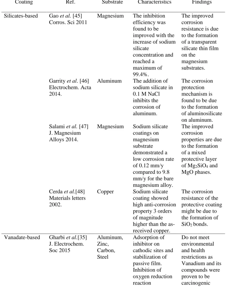
Table 2.4: Experimental and developmental technologies to replace hexavalent chromium in the corrosion protection of aluminum alloys
Coating Ref. Substrate Characteristics Findings
Silicates-based Gao et al. [45] Corros. Sci 2011
Magnesium The inhibition efficiency was found to be improved with the increase of sodium silicate concentration and reached a maximum of 99.4%. The improved corrosion resistance is due to the formation of a transparent silicate thin film on the magnesium substrates. Garrity et al. [46] Electrochem. Acta 2014.
Aluminum The addition of sodium silicate in 0.1 M NaCl inhibits the corrosion of aluminum. The corrosion protection mechanism is found to be due to the formation of aluminosilicate on aluminum. Salami et al. [47] J. Magnesium Alloys 2014.
Magnesium Sodium silicate coatings on magnesium substrate demonstrated a low corrosion rate of 0.12 mm/y compared to 9.8 mm/y for the bare magnesium alloy.
The improved corrosion
properties are due to the formation of a mixed protective layer of Mg2SiO4 and MgO phases. Cerda et al.[48] Materials letters 2002.
Copper Sodium silicate coating showed high anti-corrosion property 3 orders of magnitude higher than the as-received copper. The corrosion resistance of the protective coating might be due to the formation of SiO2 bonds. Vanadate-based Gharbi et al.[35]
J. Electrochem. Soc 2015 Aluminum, Zinc, Carbon, Steel Adsorption of inhibitor on cathodic sites and stabilization of passive film. Inhibition of oxygen reduction reaction Do not meet environmental and health restrictions as Vanadium and its compounds were proven to be carcinogenic
33 Ralston et al. [49]
J. Electrochem. Soc 2008
Aluminum NaVO3 has no effect at pH of 3 and 5 but leads to a noticeable decrease in corrosion potential and corrosion current density at pH of 8 and 10. Inhibition of Al by NaVO3 in 0.05 M sodium chloride (NaCl) solutions is associated with tetrahedrally coordinated forms of vanadate. Manganese-based Danilidis et al. Corr. Sci. 2007 Aluminum Manganese-based conversion coating provides good corrosion resistance for aluminum. The corrosion protection properties of manganese-based conversion coatings could be improved by additives. Agnesia et al. [50]
Ara J. Sci Eng 2009
Aluminum The corrosion inhibition efficiency
increases with the increase of KMnO4 concentration. Formation of Al-KMnO4 complex on the metal surface, which prevents the penetration of corrosive ions. Zirconium-based Li et al. Int. J. Electrochem. Sci. 2016
Aluminum Good corrosion protection of Al by the barrier properties of Zr-based coating. The Zr-based coating is a promising high-performance protective coating. Haibin et al. [51]
J. Mat Sci Letters 2001
Steel Polarization resistance of the Zr-based thin films was 299 Ω.cm2 as compared to 40 Ω.cm2 for as-received steel substrates. The heat treatment at high temperature leads to the formation of a dense coating.
Rare-earth-based Haque et al. [52] Resources 2014 Aluminum, Steel Mainly works as cathodic inhibitors, precipitation of Ce-oxide on cathodic sites, Minor improvement in pitting potential and corrosion current was noted
34 induced by the local pH increase Organic (including epoxy, sol-gel, polyurethane, silane, and nanocomposites) Wolf et al.[53] Springer Briens in materials 2014 Aluminum, Steel Good barrier properties Nanocomposite: cost of implementation could be too important Phosphate-based Thomas et al.[54]
Corros. Sci 2013 Aluminum, Steel, Carbon Good barrier properties provided by the precipitation of metal-phosphate compounds pH stability of phosphate-based coatings inferior to chromium oxide
35
References
[1] B. Cwalina, Biodeterioration of concrete, brick and other mineral-based building materials, Underst. Biocorrosion. (2014) 281–312.
[2] S. Michael, W. Dietrich, B. Roman, Corrosion Resistance of Aluminium and Aluminium Alloys, 2010.
[3] J.Y. Cao, M. Wang, L. Kong, L.J. Guo, Hook formation and mechanical properties of friction spot welding in alloy 6061-T6, J. Mater. Process. Technol. 230 (2016) 254–262. [4] S.A. Abdel-Gawad, M.A. Sadik, M.A. Shoeib, Preparation and properties of a novel nano
Ni-B-Sn by electroless deposition on 7075-T6 aluminum alloy for aerospace application, J. Alloys Compd. (2019).
[5] T. Maeno, K. Mori, R. Yachi, Hot stamping of high-strength aluminium alloy aircraft parts using quick heating, CIRP Ann. 66 (2017) 269–272.
[6] W.. Miller, L. Zhuang, J. Bottema, A.. Wittebrood, P. De Smet, A. Haszler, A. Vieregge, Recent development in aluminium alloys for the automotive industry, Mater. Sci. Eng. A. 280 (2000) 37–49.
[7] Y. Fu, X. Chen, B. Zhang, Y. Gong, H. Zhang, H. Li, Fabrication of nanodiamond reinforced aluminum composite coatings by flame spraying for marine applications, Mater. Today Commun. 17 (2018) 46–52.
[8] J.K. Oh, S. Liu, M. Jones, Y. Yegin, L. Hao, T.N. Tolen, N. Nagabandi, E.A. Scholar, A. Castillo, T.M. Taylor, L. Cisneros-Zevallos, M. Akbulut, Modification of aluminum surfaces with superhydrophobic nanotextures for enhanced food safety and hygiene, Food
36 Control. 96 (2019) 463–469.
[9] Y. Liu, H. Liu, Z. Chen, Post-fire mechanical properties of aluminum alloy 6082-T6, Constr. Build. Mater. 196 (2019) 256–266.
[10] E.E. (Ele E. Stansbury, R.A. (Robert A. Buchanan, Fundamentals of electrochemical corrosion, ASM International, 2000.
[11] C. Vargel, Corrosion of aluminium, Elsevier, 2004.
[12] Corrosion Testing Lab, Corrosion Testing Laboratory, Spectro Labs, (n.d.). [13] C.H. Simmons, N. Phelps, T.L.D.E. Maguire, C.H. Simmons, N. Phelps, T.L.D.E.
Maguire, Surface Finish and Corrosion of Metals, Butterworth-Heinemann, 2012. [14] Crevice Corrosion, (n.d.).
http://www.cdcorrosion.com/mode_corrosion/corrosion_crevice.htm (accessed March 24, 2019).
[15] J. Wysocka, M. Cieslik, S. Krakowiak, J. Ryl, Carboxylic acids as efficient corrosion inhibitors of aluminium alloys in alkaline media, Electrochim. Acta. 289 (2018) 175–192. [16] C.T.F. Ross, C.T.F. Ross, An overview of pressure vessels under external pressure, Press.
Vessel. (2011) 1–14.
[17] F. Ahnia, Y. Khelfaoui, B. Zaid, F.J. Pérez, D. Miroud, A. Si Ahmed, G. Alcalá,
Thermally sprayed Al/Mo coatings on industrial steel E335 and effects on electrochemical parameters in simulated acid rain, J. Alloys Compd. 696 (2017) 1282–1291.
[18] L.C. Klein, M. Aparicio, A. Jitianu, Handbook of sol-gel science and technology : processing, characterization and applications, n.d.
37
[19] S. Senani, E. Campazzi, M. Villatte, C. Druez, Potentiality of UV-cured hybrid sol–gel coatings for aeronautical metallic substrate protection, Surf. Coatings Technol. 227 (2013) 32–37.
[20] R. Naderi, M. Fedel, F. Deflorian, M. Poelman, M. Olivier, Synergistic effect of clay nanoparticles and cerium component on the corrosion behavior of eco-friendly silane sol– gel layer applied on pure aluminum, Surf. Coatings Technol. 224 (2013) 93–100.
[21] L. Li, J. He, J. Lei, W. Xu, X. Jing, X. Ou, S. Wu, N. Li, S. Zhang, A sol–bath–gel approach to prepare hybrid coating for corrosion protection of aluminum alloy, Surf. Coatings Technol. 279 (2015) 72–78.
[22] S.B. Ulaeto, R. Rajan, J.K. Pancrecious, T.P.D. Rajan, B.C. Pai, Developments in smart anticorrosive coatings with multifunctional characteristics, Prog. Org. Coatings. 111 (2017) 294–314.
[23] A.A. Al-Amiery, F.A. Binti Kassim, A.A.H. Kadhum, A.B. Mohamad, Synthesis and characterization of a novel eco-friendly corrosion inhibition for mild steel in 1 M hydrochloric acid, Sci. Rep. 6 (2016) 19890.
[24] A. Mallik, B.C. Ray, Evolution of Principle and Practice of Electrodeposited Thin Film: A Review on Effect of Temperature and Sonication, Int. J. Electrochem. 2011 (2011) 1–16. [25] W. Xu, K. Rajan, X.G. Chen, D.K. Sarkar, Facile electrodeposition of superhydrophobic
aluminum stearate thin films on copper substrates for active corrosion protection, Surf. Coatings Technol. (2019).
38
mechanism of inhibitor blend (P22SU) on mild steel corrosion in high chloride containing water, Int. J. Corros. Scale Inhib. 6 (2017) 262–275.
[27] Y.I. Kuznetsov, Progress in the science of corrosion inhibitors 1, Int. J. Corros. Scale Inhib. 4 (2015) 15–34.
[28] C.L. Page, Corrosion and protection of reinforcing steel in concrete, Woodhead Publishing, 2007.
[29] X. Li, S. Deng, H. Fu, Sodium molybdate as a corrosion inhibitor for aluminium in H3PO4 solution, Corros. Sci. 53 (2011) 2748–2753.
[30] H.J. Habeeb, H.M. Luaibi, R.M. Dakhil, A.A.H. Kadhum, A.A. Al-Amiery, T.S. Gaaz, Development of new corrosion inhibitor tested on mild steel supported by electrochemical study, Results Phys. 8 (2018) 1260–1267.
[31] N.D. Nam, P. Van Hien, N.T. Hoai, V.T.H. Thu, A study on the mixed corrosion inhibitor with a dominant cathodic inhibitor for mild steel in aqueous chloride solution, J. Taiwan Inst. Chem. Eng. 91 (2018) 556–569.
[32] C.G. Dariva, A.F. Galio, Corrosion Inhibitors-Principles, Mechanisms and Applications, in: Chapter Corros. Inhib., 2014.
[33] Y.-T. Du, H.-L. Wang, Y.-R. Chen, H.-P. Qi, W.-F. Jiang, Synthesis of baicalin
derivatives as eco-friendly green corrosion inhibitors for aluminum in hydrochloric acid solution, J. Environ. Chem. Eng. 5 (2017) 5891–5901.
[34] R.L. Twite, G.P. Bierwagen, Review of alternatives to chromate for corrosion protection of aluminum aerospace alloys, Prog. Org. Coatings. 33 (1998) 91–100.
39
[35] O. Lunder, J.C. Walmsley, P. Mack, K. Nisancioglu, Formation and characterisation of a chromate conversion coating on AA6060 aluminium, Corros. Sci. 47 (2005) 1604–1624. [36] O. Gharbi, S. Thomas, C. Smith, N. Birbilis, Chromate replacement: what does the future
hold?, 2 (2018) 12.
[37] C. Blawert, P. Bala Srinivasan, Plasma electrolytic oxidation treatment of magnesium alloys, in: Surf. Eng. Light Alloy., Woodhead Publishing, 2010: pp. 155–183.
[38] G.E.J. Poinern, N. Ali, D. Fawcett, Progress in Nano-Engineered Anodic Aluminum Oxide Membrane Development, Materials (Basel). 4 (2011) 487–526.
[39] D. Manova, J.W. Gerlach, S. Mändl, Thin Film Deposition Using Energetic Ions., Mater. (Basel, Switzerland). 3 (2010) 4109–4141.
[40] ¡j --~ World, R. Organzation, will-~ IARC MONOGRAHS ON THE EVALUATION OF CARCINOGENIC Evaluation of Carcinogenic Risks to Rumans, which met in Lyon, n.d. https://monographs.iarc.fr/wp-content/uploads/2018/06/mono49.pdf (accessed March 31, 2019).
[41] H.J. Gibb, P.S.J. Lees, P.F. Pinsky, B.C. Rooney, Lung cancer among workers in chromium chemical production, Am. J. Ind. Med. 38 (2000) 115–126.
[42] H. Oliveira, Chromium as an Environmental Pollutant: Insights on Induced Plant Toxicity, J. Bot. 2012 (2012) 1–8.
[43] R. Bartlett, B. James, Behavior of Chromium in Soils: III. Oxidation1, J. Environ. Qual. 8 (1979) 31.
![Table 2.1: Electrode potentials against saturated calomel electrode in seawater at 25 ˚C [13].](https://thumb-eu.123doks.com/thumbv2/123doknet/7483854.223882/33.918.94.820.163.1036/table-electrode-potentials-against-saturated-calomel-electrode-seawater.webp)
![Figure 2.3: Schematic illustration of the mechanism of pitting corrosion on metals [14]](https://thumb-eu.123doks.com/thumbv2/123doknet/7483854.223882/34.918.195.724.573.915/figure-schematic-illustration-mechanism-pitting-corrosion-metals.webp)
![Figure 2.4: Example of stress corrosion cracks on the external surface of the high-pressure gas transmission pipeline [15]](https://thumb-eu.123doks.com/thumbv2/123doknet/7483854.223882/36.918.172.750.105.365/figure-example-corrosion-external-surface-pressure-transmission-pipeline.webp)
![Figure 2.6: The variation of the thickness, roughness and contact angle of the fabricated films with (a) electrodeposition potential and (b) electrodeposition time [25].](https://thumb-eu.123doks.com/thumbv2/123doknet/7483854.223882/40.918.124.791.110.492/figure-variation-thickness-roughness-fabricated-electrodeposition-potential-electrodeposition.webp)
![Figure 2.8: Potentiodynamic polarization curves of the aluminum substrate in 0.1 M H 3 PO 4 without and with different concentrations of Na 2 MoO 4 [29]](https://thumb-eu.123doks.com/thumbv2/123doknet/7483854.223882/43.918.242.675.113.440/figure-potentiodynamic-polarization-curves-aluminum-substrate-different-concentrations.webp)
![Figure 2.9: Potentiodynamic polarization curves of steel substrate without and with the presence of La(dpp) 3 at different concentrations in a corrosive solution of 0.1 M NaCl [31]](https://thumb-eu.123doks.com/thumbv2/123doknet/7483854.223882/44.918.243.677.233.573/potentiodynamic-polarization-substrate-presence-different-concentrations-corrosive-solution.webp)
![Figure 2.11: Schematic illustration of the self-healing and barrier properties of chromium conversion coatings on metallic surfaces [35].](https://thumb-eu.123doks.com/thumbv2/123doknet/7483854.223882/47.918.155.754.117.408/schematic-illustration-properties-chromium-conversion-coatings-metallic-surfaces.webp)
![Figure 2.12: Bode impedance modulus plot of bare and anodized AA2024-T3 aluminum alloy in 3% NaCl solution [33]](https://thumb-eu.123doks.com/thumbv2/123doknet/7483854.223882/48.918.177.744.421.697/figure-bode-impedance-modulus-anodized-aluminum-alloy-solution.webp)