O
pen
A
rchive
T
OULOUSE
A
rchive
O
uverte (
OATAO
)
OATAO is an open access repository that collects the work of Toulouse researchers and
makes it freely available over the web where possible.
This is an author-deposited version published in :
http://oatao.univ-toulouse.fr/
Eprints ID : 16986
The contribution was presented at VTC-Fall 2016 :
http://www.ieeevtc.org/vtc2016fall/
To cite this version :
Dalce, Rejane and Van den Bossche, Adrien and Val,
Thierry A study of the ranging error for Parallel Double Sided-Two Way
Ranging protocol. (2016) In: 84th IEEE Vehicular Technology Conference
(VTC-Fall 2016), 18 September 2016 - 21 September 2016 (Montréal, Canada).
Any correspondence concerning this service should be sent to the repository
administrator:
[email protected]
A study of the ranging error for Parallel Double
Sided-Two Way Ranging protocol
Rejane Dalce, Adrien van den Bossche and Thierry Val
Institut de Recherche en Informatique de Toulouse, Universite de Toulouse, CNRS, INPT, UPS, UT1, UT2J Email: rejane.dalce, vandenbo, [email protected]
Abstract—Indicating its own position is an important ability
for a mobile wireless node. As a matter of fact, it is a key enabler for future applications in fields as diverse as routing, security, logistics, entertainment and so on. This position can be computed in many different ways. In a protocol-based approach to positionning, the foundation of this localisation service is the ranging protocol. In this paper, we focus on Time of Flight (ToF)-based localisation. We investigate the performance in terms of ranging precision of our proposed protocol, Parallel Double Sided-Two Way Ranging. We define the mathematical model which allows prediction of the error behaviour and derive a dynamic correction tool. We then implement our solution using the Decaduino platform and verify our model’s ability to identify the real distance. Using the correction method derived from the model in a real indoor environment, we were able to reduce the ranging error by at least 90%.
I. INTRODUCTION
From monitoring the elderly to power plant surveillance, Wireless Sensor Networks (WSNs) collect data in order to help enhance processes in fields as diverse as health care, agriculture, security and routing. WSNs are closely related to the Device Layer [1] of the Internet of Things (IoT), where machines or things interact with each other, collect data and also execute actions. WSNs are expected to be self-organising networks, where each node has limited computing power and a constrained energy source. Protocols designed for these networks must be scalable, and in some deployment contexts, the network may need auto-organization and self-healing skills. Nodes must also support sleeping and waking-up as the basic mechanisms to save energy. An important hypothesis in these applications is the ability of a wireless mobile node to determine its position. This ability will enable value-added services such as mapping geographical position to sensor data but will also improve the performance at the Medium Access Control (MAC) and Network (NWK) levels. At the root of positioning, we find the ranging operation, which is the action of measuring the distance through a ranging process. Wireless nodes perform ranging using a protocol defined for the physical characteristic that must be evaluated: this signal characteristic may be Received Signal Power (RSP) or Time of Flight (ToF). In this paper, we focus on ToF as it is more reliable than RSP, in the ranging context. In addition, Ultra-Wide Band (UWB) based transceivers supporting ToF-based ranging are becoming available [2]. Previously in [3], we introduced Parallel Double-Sided Two-Way Ranging (PDS-TWR) as an alternative to Symmetric Double-Sided
Two-Way [6] (SDS-TWR) and studied the overhead and energy consumption reduction which can be attained. In this work, we describe the mathematical model for the error associated with PDS-TWR. This model is then used to dynamically mitigate errors. We apply our model to real distance estimates obtained from our prototype.
The contributions of this paper are therefore twofold: first, we propose an error model for an efficient ranging protocol, then, we explain how it is possible to obtain negative distance samples using ToF.
The remainder of this paper is organised as follows: after a brief review of the existing litterature, section III introduces the ranging protocol, the error model, and the correction method. Section IV describes the prototype, the experiments, the results and provides an analysis of the impact of our dynamic correction method. We then conclude the article in section V.
II. RELATED WORK
As mentioned earlier, one of our objectives is to provide the ability for WSN nodes to autonomously determine their own position. For this service to be viable, it must be tailored to the specific constraints of embedded devices: as these have limited computing power and memory, the computations involved must be kept to a minimum. Also, WSN nodes are expected to run for a long time on a battery: the solution must have a minimal impact on the global energy consumption. In the context of localisation, reducing energy consumption means focusing on the ranging protocol.
Measuring distance with ToF using WSN nodes has become feasible in a standard manner with the integration of the Ultra-Wide Band (UWB) technology in the IEEE 802.15.4 standard [6]. A reference point is specified in all radio frames where timing information must be collected (the Ranging Marker or RMarker bit). Generating these precise timestamps upon transmission and reception of messages is a key enabler for localisation. Nowadays, compatible transceivers are becoming available. Therefore, instead of relying on simulations, we chose a prototype-based approach using the platform described in [5]. In this study, we focus on ranging as it is the first step toward accurate localisation. As a matter of fact, localisation can be broken down in three phases: first, distance collection is performed using a ranging protocol, then these pieces of information are combined to generate an estimated position. This estimation is often computed with respect to a local
reference system. An optional third step of localisation is the mapping of these local estimates with a position defined in a global reference system such as the GPS.
Unfortunately, in the real world, many factors affect per-formance. These error sources may be divided into three categories:
∙ Experiment setup : while Geometric Dilution Of
Pre-cision (GDOP) mostly affect the positioning phase, the presence of obstacles thus significant multipath will in-troduce a positive bias in the distance measurements. The performance is also influenced by the presence of metallic surfaces thus an office indoor environment will not yield the same results as an industrial context ;
∙ Ranging signal and hardware platform : although two
different platforms may implement the same concept, for example ToF, each will have some unique characteristics that will impact performance. It may be clock resolution, a minimal distance under which the results may be unreliable and so on. In this case, a calibration phase is necessary as it may help design a static correction formula [4] ;
∙ Ranging protocol : sometimes, the data
genera-tion/collection process introduces error in the observa-tions. For example, TWR, while relaxing the synchroni-sation constraint of Time Of Arrival, generally produces poor results because it does not take into account char-acteristics of the source and destination clocks.
All these errors will lead to overestimated distances, thus a significant localisation error. The error can be removed during the ranging process or during the localisation. The first scheme often involves altering the protocol. In the case of ToF, this has led to the definition of a few protocols, namely Symmetric Double Sided Two-Way Ranging TWR) [6] and SDS-TWR-Multiple Acknowledgement (SDS-TWR-MA) [7]. In [8], the authors study the relationship between the ranging error model and the environment used for the experiment. Most studies focus on error mitigation during the localisation phase. There are plenty of tools for this purpose: the Kalman filter and its various flavours [9], the particle filter [10], mathematical formulas based on a calibration phase [11], averaging of multiple measurements [12]...
We focus here on mitigating the ranging error through the pro-tocol. From the error mitigation strategies mentioned earlier, we can identify two key aspects of the cost issue: bandwidth availability and computational power. Localisation is one of the services provided by the network and not the reason for deployment. Therefore, its energy consumption must be kept low. This implies that aside from the radio exchanges required to generate the distance estimates, the nodes should not have to report data to a central server nor wait for said server to reply with the estimated position. This leads us to the computation aspect : some algorithms have the ability to produce precise estimates from noisy inputs by combining many sources of information but they also require a large amount of memory
to store the input data. Some devices may have a suitable architecture but that will probably not be the case for all. Therefore, an efficient solution must be found. A third aspect must also be taken into account: many nodes are expected to be mobile: phones, on-body sensors... Even infrastructure monitoring sensors may fall in this category as cabling is not always feasible. Enabling localisation must not be a threat to the node’s lifetime.
With these constraints in mind, we have chosen to study the precision of a specific ranging protocol named Parallel Double-Sided Two-Way Ranging (PDS-TWR). This protocol allows a mobile to measure the distance to many anchors while minimising the number of exchanged frames and the process duration. Energy consumption and medium usage constraints are therefore taken into account by the protocol itself.
Specifically, we want to study the ranging precision of PDS-TWR, and use this knowledge to improve its performance. Since we focus on the inherent properties of PDS-TWR, the experiments will be conducted in Line-Of-Sight situation. We will focus on the relationship between the clock quality and the ranging error. Although similar studies have been conducted for SDS-TWR-MA [7] and SDS-TWR [6], they only stopped at characterising the error. Our final objective is to provide a dynamic correction method which will enable error suppression with no additional cost in terms of network bandwidth, making PDS-TWR an interesting alternative to SDS-TWR.
III. PROPOSED PROTOCOL,ERROR MODEL AND DYNAMIC CORRECTION METHOD
This section introduces the ranging protocol and the asso-ciated error model.
A. Ranging protocol
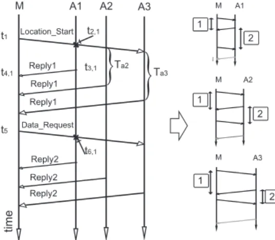
Figure 1 illustrates the frame exchanges taking place in PDS-TWR. The mobile broadcasts a Location-Start message containing the ordered list of anchors with which it wishes to perform ranging. By reducing the time spent listening for incoming frames and also sending messages, PDS-TWR reduces the energy consumption of the localisation process. The protocol specification reduces both the number and size of the messages.
Ranging measurements have been performed with PDS-TWR. In [3], we compared the performance of PDS-TWR and SDS-TWR and noticed that the ranging error with PDS-TWR was greater than SDS-TWR’s. Moreover, the error changed with the order in which the anchors replied. Experiments in various environments confirmed the idea that the error originated from the combination of our hardware, i.e. ranging timer precision, and the specific ranging protocol. In order to investigate this error, we developed the model presented in the following subsection.
B. Error model
Let ˆ𝑡𝑓,𝑖 be the estimated ToF associated with the i-th
time M A1 A2 A3 M M 1 2 1 1 2 2 M A1 Location_Start Reply1 A2 A3 Reply1 Reply1 Data_Request Reply2 Reply2 Reply2 Ta2 Ta3
}
}
t2,1 t6,1 tim e t3,1 t4,1 t1 t5Fig. 1. PDS-TWR protocol sequence diagram and symmetry repartition
the theoretical value while equation 2 gives the expression of ˆ
𝑡𝑓,𝑖for our protocol.
4𝑡𝑓,𝑖= (𝑡4,𝑖− 𝑡1) − (𝑡3,𝑖− 𝑡2,𝑖) + (𝑡6,𝑖− 𝑡3,𝑖) − (𝑡5− 𝑡4,𝑖) (1)
4ˆ𝑡𝑓,𝑖 = (𝑡4,𝑖− 𝑡1)(1 + 𝑒𝑀) − (𝑡3,𝑖− 𝑡2,𝑖)(1 + 𝑒𝐴𝑖) (2)
+ (𝑡6,𝑖− 𝑡3,𝑖)(1 + 𝑒𝐴𝑖) − (𝑡5− 𝑡4,𝑖)(1 + 𝑒𝑀)
Variables 𝑒𝑀 and𝑒𝐴𝑖 express the difference between a
dura-tion measured with the PHY of a node and the real duradura-tion, expressed in parts per million (ppm), at the mobile M and anchor Ai. Equation 2 indicates the effect of these errors on the timestamps collected through the use of PDS-TWR. The expression can be rewritten by grouping all terms that were not multiplied by variables 𝑒𝑀 and 𝑒𝐴𝑖, making the
expression corresponding to 4𝑡𝑓,𝑖 appear in the equation. As
this expression is applied to each anchor, the relationship between the anchor’s position in the list and the error becomes evident. For example, equations 3 and 4 can be applied to the case where two anchors are used while equations 5, 6 and 7 correspond to the execution of PDS-TWR with 3 anchor. We suppose A1 replies first, then A2 D seconds later and then A3
D seconds after A2.
𝐴1 : 4(ˆ𝑡𝑓,1− 𝑡𝑓,1) = −𝐷(𝑒𝑀− 𝑒𝐴1) + 2𝑡𝑓,1(𝑒𝑀+ 𝑒𝐴1) (3)
𝐴2 : 4(ˆ𝑡𝑓,2− 𝑡𝑓,2) = 𝐷(𝑒𝑀− 𝑒𝐴2) + 2𝑡𝑓,2(𝑒𝑀+ 𝑒𝐴2) (4)
𝐴1 : 4(ˆ𝑡𝑓,1− 𝑡𝑓,1) = −2𝐷(𝑒𝑀− 𝑒𝐴1) + 2𝑡𝑓,1(𝑒𝑀+ 𝑒𝐴1) (5)
𝐴2 : 4(ˆ𝑡𝑓,2− 𝑡𝑓,2) = 0 (6)
𝐴3 : 4(ˆ𝑡𝑓,3− 𝑡𝑓,3) = 2𝐷(𝑒𝑀− 𝑒𝐴3) + 2𝑡𝑓,3(𝑒𝑀+ 𝑒𝐴3) (7)
The main term of the ranging error can therefore be predicted using equation 8.
4(ˆ𝑡𝑓,𝑘− 𝑡𝑓,𝑘) = 𝐷(2𝑘 − 𝑛 + 1)(𝑒𝑀− 𝑒𝐴𝑘), 𝑘 = 1, 2...𝑛 (8)
The ranging error varies because of the lack of symmetry between the measurements. For example, when two anchors are used, the two TWRs associated with A1 are not identical in their global duration. When 3 anchors are used, the anchor
in the middle is expected to have the smallest ranging error because the two TWRs are quasi symmetrical. This situation is illustrated on figure 1. The execution of PDS-TWR is shown for each anchor on the right side of figure 1. The two TWRs are labelled 1 and 2 and their respective durations are shown as a double-headed arrow. Due to the delays between the transmission of the replies,𝑇 𝑊 𝑅1and𝑇 𝑊 𝑅2are different in
size for node A. This behaviour corresponds to the following factor in equation 8: (2k-n+1). Numerical applications with varying values of n and k show that this factor is minimal when n is an odd number and k equals floor(n/2)+1, thus corresponds to the anchor in the middle (equations 5, 6 and 7).
C. Ranging correction
As the experiments have shown, the error depends on the position of the anchor in the list broadcasted by the tag. We will now focus on removing the ranging error using the mathematical model. We use the formula given in equation 8. The product of the real ToF value and the sum of the tolerances has been left out as it is very small (ns*ppm) compared to the first term. We then rewrite the equation as equation 9.
𝑡𝑓,𝑘= ˆ𝑡𝑓,𝑘− 𝐷 ⋅ (2𝑘 − 𝑛 + 1) ⋅ (𝑒𝑀− 𝑒𝐴𝑘)/4, 𝑘 = 1, 2...𝑛 (9)
Therefore, we can extract the real ToF 𝑡𝑓,𝑘 using the known
delay between the answers, the estimated ToF and the values of𝑒𝑀 and𝑒𝐴𝑘. The last two parameters correspond to the drift
difference between the nodes. This drift difference is measured during the reception of any UWB message: it is proportional to the skew which is the difference between the sender and receiver frequencies. In order for the incoming message to be properly decoded, the receiver must adjust its clock (delaying or advancing it) in order to match the remote end during the Synchronisation Header. This adjustment value corresponds to 𝑒𝑀 - 𝑒𝐴𝑘 and is readily available through the library
presented in [5]. This correction could be further improved by replacing the configured value of D with the difference between timestamps. As shown in figure 1, the messages from A1 and A2 for example are separated by the delay defined in the protocol. The difference between their arrival times would be a more precise estimate of the real delay.
Finally, since all the necessary pieces of information are generated by the execution of the ranging process, no prelim-inary calibration is required and our correction method can be considered as dynamic.
IV. RESULTS
In this section, we present the results obtained from our testbed and the applied processing. The objective is to adjust the measurement in a completely dynamic manner, without any prior knowledge regarding the test setup. We will describe the experiment and the ranging results obtained using 2 then 3 anchors without correction. Then we will see how the dynamic correction method can be used to enhance the measurements.
0 1 2 3 4 5 6 7 8 -4 -2 0 2 4 6 8 10 Reference distance (m) E s ti mat e d d is tan ce (m ) real distance A1 A2
Fig. 2. Ranging results with a mobile and two anchors
A. Test setup
Our prototype uses the DecaDuino [5] platform designed in our facility. Our experiments involve a mobile node and
n anchors, n being either two or three depending on the experiment. The anchors were placed side by side and the mobile moved away from them along a straight line, stopping every 30 cm to collect 100 samples. Each sample consisted of the drift difference measured while receiving frames Reply1 and Reply2 and the estimated distance. The current imple-mentation does not combine successive samples in the error mitigation process: each estimated distance sample is pro-cessed using the data generated while measuring this distance. We insist on the fact that we are interested in the ranging error, not the localisation error. Thus, placing the anchors side by side in our experiments allows us to compare the distance estimates produced at a common reference distance. This anchor placement is not suitable for localisation as it would maximise the GDOP: in such a configuration, considering that each anchor can build a ring centred on itself and containing the mobile node, the intersection of the rings would be very large even though the original ranging was precise.
B. Ranging results from testbed before dynamic correction
In this sub-section, we introduce the ranging results of these measurement campaigns along with their processing.
1) PDS-TWR with two anchors: Figure 2 shows the results of the first experiment. The mean distance estimate for each reference distance is given for anchors A1 and A2. We can see that the ranging results are quite precise but not so accurate: with A1, the absolute mean error is about 150cm, while with A2, the it is about 250cm. As expected, the error depends on the anchor: both curves are far from each other and a static correction like the one used in [11] would not be appropriate.
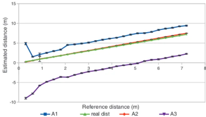
2) PDS-TWR with three anchors: In the case where 3 anchors are used, we can verify one of the predictions of our model: the anchor in the middle of the list, A2, is linked to the best ranging results. As shown on figure 3, while anchors A1 and A3 present a significant error, without any processing, the estimates obtained using A2 are very close to the real distance. The maximum error in this case is 28 cm, which corresponds to a ToF value of a little less than 1ns. Both experiments sometimes yield negative distance estimates. While it may
0 1 2 3 4 5 6 7 8 -10 -5 0 5 10 15 A1 real dist A2 A3 Reference distance (m) Est ima te d d ist a n ce (m)
Fig. 3. Ranging results with a mobile and three anchors
seem like they should be filtered out, these values will be kept for processing. As a matter of fact, the negative distance is a direct consequence of Two-Way Ranging-based distance measurement. To compute the propagation time, the duration measured by the anchor is subtracted from the duration mea-sured by the tag. If the anchor’s clock is faster than the tag’s, the returned value may be greater than the one produced by the tag. Therefore, the estimated ToF and the derived distance are negative. The upcoming section will show how our method allows us to recover from this.
C. Ranging results from testbed with dynamic correction enabled
Using the understanding gained from the ranging error model, we designed a simple correction algorithm which is executed by the mobile node in order to adjust the mea-surements without any knowledge regarding the real distance. We will begin with the two anchors experiment. In [3], we performed a similar experiment and inverted the reply order; we then observed that altering the reply order had an impact on the results. This time, we directly used the results from this experiment and applied our dynamic correction method. From the estimated distance, we computed the estimated ToF ˆ𝑡 and applied the formula given in equation 9 to estimate the true ToF value, thus the real distance.
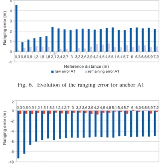
Figures 4 and 5 summarise the impact of our correction on the ranging error. The raw error corresponds to the ranging error present in the raw measurements. The remaining error has been computed after the adjustment. In both cases, the final ranging error is below 40cm on the real testbed. This corresponds to an error reduction of at least 90%. Finally, we processed the results of the experiment involving 3 anchors. This time, only the results of the first and last node on the list will be processed. We replaced k and n with their values (n=2 and k in{0,1,2}) and obtained the appropriate equations. The results for A2 remain the same. Since an odd number of anchors is used, the model predicts minimal error for the anchor in the middle of the list. Figure 6 and 7 show the evolution of the error for each anchor. This time, the remaining error is always under 60cm: there is therefore still room for improvement. Nevertheless, we consider that the results fit our model. Our correction method can therefore be considered efficient
0,3 0,6 0,9 1,2 1,5 1,8 2,1 2,4 2,7 3 3,3 3,6 3,9 4,2 4,5 4,8 5,1 5,4 5,7 6 6,3 6,6 6,9 7,2 -0,5 0 0,5 1 1,5 2 2,5
raw error A1 remaining error A1 Reference distance (m) R a n g in g e rro r (m )
Fig. 4. Evolution of the ranging error for anchor A1 (PDS-TWR 2 anchors)
-4,5 -4 -3,5 -3 -2,5 -2 -1,5 -1 -0,5 0 0,5
raw error A2 remaining error A2 Reference distance (m) ra n g in g e rro r (m ) 0,3 0,6 0,9 1,2 1,5 1,8 2,1 2,4 2,7 3 3,3 3,6 3,9 4,2 4,5 4,8 5,1 5,4 5,7 6 6,3 6,6 6,9 7,2
Fig. 5. Evolution of the ranging error for anchor A2 (PDS-TWR 2 anchors)
0,3 0,6 0,9 1,2 1,5 1,8 2,1 2,4 2,7 3 3,3 3,6 3,9 4,2 4,5 4,8 5,1 5,4 5,7 6 6,3 6,6 6,9 7,2 -1 0 1 2 3 4 5 Reference distance (m) R a n g in g e rro r (m )
raw error A1 remaining error A1
Fig. 6. Evolution of the ranging error for anchor A1
0,3 0,6 0,9 1,2 1,5 1,8 2,1 2,4 2,7 3 3,3 3,6 3,9 4,2 4,5 4,8 5,1 5,4 5,7 6 6,3 6,6 6,9 7,2 -10 -8 -6 -4 -2 0 2 Reference distance (m) R a n g in g e rro r (m )
raw error A3 remaining error A3
Fig. 7. Evolution of the ranging error for anchor A3
and scalable: it does not require a great effort to neither implement nor use (no calibration phase, no environment model to design, simple enough for the targeted CPU) yet the correction algorithm provides good results, appropriate for an indoor environment.
It can be considered scalable since the drift difference is hardware-computed by the transceiver while receiving any message from a neighbour. No extra communication is re-quired in order to acquire the inputs of our correction method.
Deploying our solution over a large network will therefore not affect bandwidth availability.
V. CONCLUSION
A direct consequence of measuring any physical quantity is the introduction of measurement errors. Suppressing these errors is sometimes a daunting task. In this paper, we studied the ranging error inherent to our ranging protocol, PDS-TWR. We modelled this ranging error as a function of the delays defined by the protocol and the clock differences between the tag and anchors. We verified the validity of our model by using the derived correction method in a real world setup to dynamically adjust distance estimates. We therefore provided a completely dynamic and scalable correction scheme as it re-quires neither prior knowledge about the distance nor extensive measurements which will affect bandwidth availability. This simple yet effective method was able to reduce the ranging error by at least 90% in real world experiments based on the UWB technology. This translates to a mean error of 40cm in a real setup using 2 anchors. Nevertheless, there is still room for improvement. We plan on studying the impact of various smoothing methods on performance, both at the ranging level and at the localisation level. Then, we will continue our exploration of the possibilities for NLOS identification offered by recent transceivers. With this, we hope to bring green accurate localisation to the things surrounding us.
REFERENCES
[1] Khan, R.; Khan, S.U.; Zaheer, R.; Khan, S., ”Future Internet: The Internet of Things Architecture, Possible Applications and Key Challenges,” in Frontiers of Information Technology (FIT), 2012 10th International Conference on , vol., no., pp.257-260, 2012 doi: 10.1109/FIT.2012.53 [2] T. Ye, M. Walsh, P. Haigh, J. Barton, A. Mathewson, B. OFlynn,
Experimental Impulse Radio IEEE 802.15.4a UWB Based Wireless
Sen-sor Localization Technology: Characterization, Reliability and Ranging,
ISSC 2011, Dublin, 2011
[3] R. Dalce, A. van den Bossche, T. Val, An experimental performance study of an original ranging protocol based on an IEEE 802.15.4a UWB
testbed, IEEE ICUWB, Paris, 2014
[4] M. Yavari and B.G. Nickerson, Ultra Wideband Wireless Positioning
Systems, Technical Report TR14-230, 2014
[5] A. van den Bossche, R. Dalce, N. I. Fofana, T. Val, DecaDuino: An Open Framework for Wireless Time-of-Flight Ranging Systems, IEEE/IFIP Wireless Days, 2016
[6] IEEE Computer Society, Specific requirements Part 15.4: Wireless Medium Access Control (MAC) and Physical Layer (PHY) Specifications for Low-Rate Wireless Personal Area Networks (WPANs) Amendment
1: Add Alternate PHYs, IEEE Standard for Information technology
Telecommunications and information exchange between systems (2011) [7] H. Kim, Double-Sided Two-Way Ranging Algorithm to reduce ranging
time, IEEE Communication Letters, vol. 13, No. 7, 2009
[8] Y. Yang, Y. Zhao, M. Kyas, A Non-parametric Modeling of Time-of-Flight
Ranging Error for Indoor Network Localization, Globecom, 2013
[9] T. Gaedeke, M. Johnson, M. Hedley, W. Stork, Fusion of Wireless
Rang-ing and Inertial Sensors for Precise and Scalable Indoor Localisation,
ICC Workshop on Advances in Network Localisation and Navigation, 2014
[10] Y. Zhao, Y. Yang, M. Kyas, Dynamic searching particle filtering scheme
for indoor localization in wireless sensor network, 9th WPNC, Dresden,
Germany, 2012
[11] R. Dalce, A. van den Bossche, T. Val, Towards a new range-based
localization method for WSNs: Challenges, Constraints and Correction,
IEEE ICWCUCA, 2012
[12] A.I. Baba, M.M. Atia, Burst mode symmetric double sided two way
ranging, IFIP Wireless Days (WD 2011), Niagara Falls, ON, Canada,