T
T
H
H
È
È
S
S
E
E
En vue de l'obtention du
D
DO
OC
C
T
T
OR
O
RA
AT
T
D
DE
E
L
L’
’U
UN
N
IV
I
VE
E
RS
R
SI
IT
TÉ
É
D
DE
E
T
T
O
O
UL
U
L
OU
O
U
SE
S
E
Délivré par L’UNIVERSITE TOULOUSE III – PAUL SABATIERSpécialité : GENIE CIVIL
JURY M. Pierre ROSSI M. David BIGAUD M. Frédéric DUPRAT M. Alain SELLIER M. Anaclet TURATSINZE
Examinateur Directeur de Recherche LCPC Paris
Rapporteur Professeur des Universités, Université d’Angers
Examinateur Maître de conférences – HDR
INSA Toulouse
Examinateur Professeur des Universités, Université de Toulouse III Invité Maître de conférences – HDR Université de Toulouse III
Ecole doctorale : Mécanique Energétique Génie civil Procédés
Unité de recherche : Laboratoire Matériaux et Durabilité des Constructions Directeur de Thèse : M. Anaclet TURATSINZE
Rapporteur: Pr. Zahid Ahmad SIDDIQI, University of Engg. & Tech. Lahore, Pakistan
Présentée et soutenue par Rashid HAMEED Le 06 Octobre 2010
Apport d’un Renfort de Fibres sur les Performances des Structures en Béton Armé pour les Applications Parasismiques
The research study reported in this thesis has been performed in the Laboratory of Materials and Durability of Constructions (LMDC) Toulouse, France.
Doing research and writing a thesis is the result of the efforts of not only one person, but many. Some contribute directly to the thesis by providing guidance, constructive comments or technical support. Others do not contribute directly, but provide encouragement and support. I would like to thank all of them for their contribution to this work.
First of all, I would like to express my sincere gratitude to Professor Ginette Arliguie for having given me the opportunity to work on this research study in LMDC in an excellent working environment with good facilities and nice colleagues.
I am deeply indebted to my supervisors Anaclet Turatsinze, Frédéric Duprat and Alain Sellier for their suggestions, advices and for sharing their knowledge and research skills.
I would like to express my gratitude to the members of the thesis defense committee, Dr Pierre Rossi from LCPC Paris, Professor David Bigaud from University of Angers and Professor Zahid Ahmed Siddiqi from University of Engineering & Technology Lahore, Pakistan for their interest in my research work and the time and effort they put into reading this thesis.
I would like to thank to LMDC technical staff, René Boujou, Bernard Attard, David Dottor and Frédéric Leclerc for their good cooperation and devoted assistance throughout the experimental part of this study.
The Higher Education Commission (HEC), Pakistan is gratefully acknowledged for its financial support to this research study.
I would like to thank all of my colleagues – former and present - for the good work environment and the fruitful discussions we had during my time at LMDC Toulouse.
At a personal level, I wish to especially thank my parents for everything they have done, and even sacrificed, to help me reach this point. I also wish to mention a special thanks to Uzma, my wife, for helping me with every single facet of this effort and showing constant patience throughout this journey. I would like also to express my sincere gratitude to my brothers and sisters in Pakistan for their prayers and encouragement.
Finally, and above all, my gratitude towards God, who is faithful beyond human comprehension, cannot be expressed by words. Without the help of God, I am sure that this thesis would not have seen the light of this day.
Ce travail a été accompli au sein du Laboratoire Matériaux et Durabilité des Constructions (LMDC) de Toulouse, France.
Réaliser un travail de recherche et rédiger une thèse est le résultat des efforts non seulement d'une personne, mais de plusieurs. Certaines contribuent directement en fournissant des conseils, des commentaires constructifs ou un support technique. D'autres ne contribuent pas directement, mais apportent leur encouragement et leur soutien. Je tiens à remercier toutes ces personnes pour leur contribution à ce travail.
Tout d'abord, je tiens à exprimer ma sincère gratitude au professeur Ginette Arliguie pour m'avoir donné l'occasion de travailler sur cette étude de recherche au sein du LMDC, dans un excellent environnement de travail avec de bonnes installations et des bons collègues.
Je suis également très reconnaissant envers mes superviseurs Anaclet Turatsinze, Frédéric Duprat et Alain Sellier pour leurs suggestions, conseils, encouragements et pour le partage de leurs connaissances et de leurs compétences.
Je tiens à exprimer ma gratitude aux membres de jury, Monsieur Pierre Rossi du LCPC (Paris), le professeur David Bigaud de l’université d’Angers et le professeur Zahid Ahmed Siddiqi de University of Engineering & Technology (UET) Lahore, Pakistan, de leur intérêt pour mon travail de recherche, du temps et des efforts qu'ils ont consacré à l'expertise de cette thèse.
Je tiens à remercier les personnels techniques du LMDC, René Boujou, Bernard Attard, David Dottor et Fréderic Leclerc pour leur bonne coopération et assistance tout au long de la partie expérimentale de cette étude.
J'adresse toute ma reconnaissance à la Higher Education Commission (HEC), Pakistan, pour le soutien financier accordé pour cette étude.
Je tiens à remercier tous mes collègues - anciens et actuels - pour le bon environnement de travail qu'ils ont créé et pour les discussions fructueuses que nous avons eues pendant mon séjour au LMDC.
Personnellement, je tiens à remercier tout particulièrement mes parents pour tout ce qu'ils ont fait, et même sacrifié, pour m'aider à parvenir au point où j'en suis aujourd'hui. Je tiens également à adresser à Uzma, ma femme, une attention toute spéciale pour m'avoir aidé et avoir fait preuve de patience constante tout au long de ce voyage. Je voudrais également exprimer ma sincère gratitude à mes frères et sœurs au Pakistan pour leurs prières et leurs encouragements.
Enfin, et surtout, ma gratitude envers Dieu, qui est fidèle au-delà de la compréhension humaine, ne peut être exprimée par des mots. Sans l'aide de Dieu, je suis sûr que cette thèse n'aurait pas vu la lumière de cette journée.
Title of thesis: Contribution of metallic fibers on the performance of reinforced concrete
structures for the seismic application
Director of Thesis: Anaclet TURATSINZE
Co-Directors of Thesis: Frédéric DUPRAT and Prof. Alain SELLIER
In October 2005, an earthquake of intensity 7.4 on Richter scale hit the northern areas of Pakistan and caused 80 thousand deaths and severe damages to structures. Poor construction materials and lack of seismic design considerations were the two major reasons of this severe damage.
Structures survive a seismic event depending mainly on their capacity for energy dissipation. The greater the energy dissipated, the better is the structure performance. In Pakistan, usual practice is to use normal strength reinforced concrete as a construction material. One of the main objectives of this study is to respond to an important question: is it possible to improve the properties of normal strength reinforced concrete for the seismic application?
Fiber reinforcement is commonly used to provide toughness and ductility to brittle cementitious matrices. The present study aims to evaluate the contribution of two different types of metallic fibers in hybrid form to improve the mechanical properties, energy dissipation in particular, of normal strength reinforced concrete. A special kind of fiber (FibraFlex) capable of restraining micro-cracking effectively and commonly used carbon steel hooked-ends fibers (Dramix) capable of restraining macro-cracking have been investigated in mono and hybrid forms. The first is qualified as non-sliding fiber while the second is considered as sliding fiber. The maximum content of fiber in mono and hybrid form investigated in this research study was 40 kg/m3 and 80 kg/m3 respectively.
The results of reverse cyclic flexural loading tests performed on reinforced fibrous concrete beams having conventional steel ratio (1) equal to 0.19%, showed that the FibraFlex fibers provide an important gain in energy dissipation at low levels of displacement amplitude. At large displacement amplitude, role of Dramix fibers is more significant to improve energy dissipation. As a result of different action of each fiber at different displacement amplitude levels, a significant increase in energy dissipation capacity of RC beam was registered when both fibers were used in hybrid form at content of 80 kg/m3 (40 kg/m3 of each type of fiber). A 3D numerical model to predict the behaviour of concrete matrix reinforced with sliding and non-sliding fibers both in mono and hybrid forms is proposed. Considering fiber reinforced concrete as two phases composite, constitutive behaviour laws of plain concrete and sliding fibers were described and then they were combined according to anisotropic damage theory to predict the mechanical behaviour of FRC. The behaviour law used for the plain concrete is based on damage and plasticity theories. The behaviour law of the action of sliding fibers (Dramix) in the matrix is based on the effective stress carried by the fibers when they bridge the crack which depends on a damage parameter related to on one hand, on the content and the mechanical properties of the fiber and on the other hand, on the fiber-matrix bond.
To treat non-sliding fiber, a simplified approach is proposed in which constitutive law of plain concrete is used with increased value of fracture energy obtained from the direct tensile test on concrete reinforced with non-sliding fibers. Finally, to simulate the behaviour of hybrid
fiber reinforced concrete, approaches to model sliding and non-sliding fibers are combined without any additive equation.
A simplified approach to model the steel-concrete interface in case of reinforced concrete elements has also been proposed. This approach considers the steel-concrete interface as bond element with isotropic elasto-plastic properties. Infect the bond element replaces the steel bar area and steel bar is modelled as uniaxial bar element with elastic–plastic perfect behaviour law. Fitting of this approach was done by simulating pull-out and uniaxial tensile loading tests on RC specimens.
3D model for FRC composites and simplified approach for steel-concrete interface with fitted parameters were then used to simulate the flexural behaviour of reinforced fibrous concrete beam. Modelling results showed good agreement with experimental results.
Keywords: concrete; reinforced; metallic fibers; hybrid reinforcement; mechanical tests;
damage; energy dissipation; damping; seismic design; numerical modelling; steel-concrete interface
Titre de Thèse: Apport d’un renfort de fibres sur les performances des structures en béton
armé pour les applications parasismiques
Directeur de Thèse: Anaclet TURATSINZE
Co-Directeurs de Thèse: Frédéric DUPRAT and Prof. Alain SELLIER
En Octobre 2005, un tremblement de terre, 7.4 sur l’échelle de Richter a frappé le nord du Pakistan et a causé 80 000 décès et a sévèrement endommagé des structures. La qualité des matériaux de construction et les lacunes dans l’application des règles parasismiques ont été les deux principales causes de l’ampleur de la catastrophe.
Pour une structure, survivre à un événement sismique dépend principalement de sa capacité à dissiper l'énergie qui lui est transmise. Plus l'énergie dissipée est importante, meilleure est la performance de la structure. La pratique courante est d'utiliser le béton armé ordinaire comme matériau de construction. Un des principaux objectifs de cette étude est de répondre à une question subséquente: est-il possible d’améliorer les propriétés du béton armé ordinaire pour les applications parasismiques?
Un renfort par des fibres est habituellement utilisé pour améliorer la ténacité et la ductilité des matériaux à base cimentaires, réputés fragiles. La présente étude vise à évaluer la contribution d’un renfort mixte de deux types de fibres métalliques pour améliorer les propriétés mécaniques en particulier la capacité de bétons armés ordinaires à dissiper l’énergie. Un type particulier de fibres (FibraFlex), qualifié de non glissant, capable de contrôler efficacement les micro-fissures et des fibres Dramix à crochets, qualifiées de glissantes, capables de contrôler les macro-fissures ont été étudiées individuellement ou sous forme de renfort mixte. Le dosage maximal en fibres était de 40 kg/m3 lorsqu’un seul type de fibre a été utilisé alors qu’il était de 80 kg/m3 dans le cas d’un fibrage mixte.
Les résultats des essais de chargement cyclique alterné en flexion effectués sur les poutres en béton avec renforcement classique au taux de 0.19% combiné avec un renfort par des fibres métalliques a montré que, pour des déplacements de faible amplitude, les fibres FibraFlex confèrent un gain important dans la capacité de dissipation d'énergie. En revanche, pour des déplacements de grande amplitude, le rôle des fibres Dramix devient prépondérant pour améliorer cette capacité à dissiper de l'énergie. A la suite de l'action de chaque type de fibre à différents niveaux d'amplitude des déplacements, une augmentation significative de la capacité de dissipation de l'énergie de la poutre en béton armé a été enregistrée lorsqu’un fibrage mixte a été utilisé à raison de 80 kg/m3 (40 kg/m3 pour chaque type de fibre).
Un modèle numérique 3D pour prédire le comportement du béton renforcé par des fibres glissantes et non-glissantes sous forme monotype ou sous forme mixte est proposé. Considérant le béton renforcé par des fibres (BRF) comme un composite à deux phases, les lois de comportement du béton ordinaire et la contribution des fibres glissantes ont été décrites. Elles ont ensuite été rassemblées en fonction de la théorie anisotrope endommageable pour prédire le comportement mécanique de BRF. La loi de comportement utilisé pour le béton ordinaire est basée sur les théories de l’endommagement et de la plasticité. La loi de comportement de fibres glissantes (Dramix) est basée sur la contrainte effective reprise par les fibres pour contrôler la fissure : elle dépend des caractéristiques de la
fibre et d’un paramètre d’endommagement caractérisant la dégradation de l’interface fibre-matrice.
Pour traiter les fibres non- glissantes, une approche simplifiée est proposée dans laquelle la loi de comportement du béton ordinaire est utilisé avec une valeur accrue de l'énergie de rupture obtenue par le biais de l'essai de traction directe sur le BRF. Enfin, pour simuler le comportement des composites avec un renfort mixte, les contributions des fibres glissantes et des fibres non-glissantes sont combinées et ceci sans recourir à une équation supplémentaire. Une approche simplifiée pour modéliser l'interface acier-béton dans le cas d'éléments en béton armé a été également proposée. Cette approche considère l'interface acier-béton comme un élément de liaison avec les propriétés isotrope élasto-plastique tandis que la barre en acier est modélisée comme un élément de barre uniaxiale avec un comportement élasto-plastique parfait. Cet outil a été testé en simulant un essai d’arrachement ainsi qu’un essai tirant sur des échantillons de béton armé.
Le modèle 3D pour BRF ainsi que l’approche simplifiée pour l'interface acier-béton avec des paramètres ajustés ont ensuite été utilisés pour simuler le comportement en flexion de poutre en béton avec renforcement classique et avec un renfort de fibres métalliques. Les résultats de cette modélisation se sont révélés en bon accord avec les résultats expérimentaux.
Mots-Clés: béton armé; fibres métalliques; fibrage mixte; essais mécaniques;
endommagement; dissipation de l’énergie; amortissement; conception parasismique; model numérique; l'interface acier-béton
R. Hameed, A. Turatsinze, F. Duprat, and A. Sellier, ‘A study on the fibrous reinforced concrete elements subjected to uniaxial tensile loading’, KSCE Journal of Civil Engineering, 2010, 14(4), pp 547-556
R. Hameed, A. Turatsinze, F. Duprat, and A. Sellier, ‘Study on the Flexural Properties of Metallic Hybrid Fiber-Reinforced Concrete’, Maejo Int. J. Sci. Technol. 2010, 4(02), pp 169-184
R. Hameed, A. Turatsinze, F. Duprat, and A. Sellier, ‘Metallic fiber reinforced concrete: effect of fiber aspect ratio on the flexural properties’, ARPN Journal of Engineering and Applied Sciences (ISSN 1819-6608), Vol.4, No.5, July 200, pp 67-72
R. Hameed, A. Turatsinze, F. Duprat, and A. Sellier, ‘Positive synergy between two different metallic-fibers: effect on the flexural properties of fiber reinforced concrete’, the first international conference on sustainable built environment infrastructures in developing countries, SBEIDCO ENSET, Oran (Algeria) 12-14 October 2009
R. Hameed, A. Turatsinze, F. Duprat, and A. Sellier, ‘Experimental study on the flexural behaviour of reinforced fibrous concrete beams’, International Symposium on Brittle Matrix Composites, BMC9, Staszic Palace, Warsaw, POLAND, 25-28 October 2009
R. Hameed, F. Duprat, A. Turatsinze, and A. Sellier, ‘Mechanical properties of reinforced fibrous concrete beams under reverse cyclic loading’, the first international conference on sustainable built environment infrastructures in developing countries, SBEIDCO ENSET, Oran (Algeria) 12-14 October 2009
R. Hameed, F. Duprat, A. Turatsinze, and A. Sellier, ‘Metallic Fibers as Energy Dissipator in RC Beams under Reverse Cyclic Loading’, to be presented in CEC-2010 - Construction under Exceptional Conditions, Hanoi, Vietnam, 29th October 2010
LIST OF FIGURES ... xix
LIST OF TABLES ... xxxi
GENERAL INTRODUCTION ... 3
INTRODUCTION GENERALE ... 11
Chapter I: Literature Review ... 17
I.1. Historical Review of Concrete... 19
I.2. Earthquakes ... 21
I.3. Seismic Design: Fundamental Concept ... 21
I.3.1. Design Limit States ... 22
I.3.2. Economic Considerations... 22
I.4. Seismic Design Considerations... 23
I.5. Construction Material... 23
I.6. Fiber Reinforced Concrete Composites ... 24
I.6.1. Cementitious Matrix... 25
I.6.2. Fibers for Cementitious Matrices ... 25
I.7. Types of Fibers ... 27
I.7.1. Steel Fibers ... 27
I.7.2. Synthetic Fibers... 29
I.7.3. Natural Fibers ... 29
I.8. Static Mechanical Properties of Steel Fiber Reinforced Concrete (SFRC) ... 31
I.8.1. Compressive Strength ... 32
I.8.2. Tensile Strength... 33
I.8.3. Flexural Strength ... 37
I.8.5. Shear Strength ... 40
I.8.6. Torsion ... 45
I.8.7. Fatigue ... 49
I.8.7.1. Fatigue and Steel Fiber Reinforced Concrete ... 49
I.9. Hybrid Fiber Reinforced Concrete (HyFRC)... 53
I.9.1. Introduction ... 53
I.9.2. Research Studies on HyFRC ... 56
I.9.2.1. Wu Yao et al, 2003... 56
I.9.2.2. A. Sivakumar and M. Santhanam, 2007... 58
I.9.2.3. Y. Mohammadi et al, 2003... 60
I.9.2.4. Banthia N. and Gupta R., 2004 ... 63
I.10. Reinforced Fibrous Concrete ... 64
I.10.1. Cracking Behaviour of Reinforced Fibrous Concrete Beam... 66
I.10.2. Flexural Capacity of RFC Beam: Analytical Modelling... 68
I.10.2.1. Model of Henager and Doherty, 1976... 69
I.10.2.2. Analytical Model of G. Campione, 2008 ... 70
I.10.2.2.1. Cracking Moment ... 70
I.10.2.2.2. Yielding Moment ... 70
I.10.2.2.3. Ultimate Moment ... 72
I.10.3. Model of Ramzi B. et al, 1999 ... 73
I.10.4. P. Casanova and P. Rossi, 1997 ... 75
I.10.5. Flexural Deflection of RFC Beam ... 80
I.11. Numerical Modelling of FRC composites ... 81
I.11.1. Introduction ... 81
I.11.2. Continuum Damage Mechanics ... 82
I.11.3.1. Model of G. Camps et al, 2008 ... 86
I.11.3.2. F.K.F. Radtke et al, 2010 ... 89
I.11.3.3. J. Zhang and V. C. Li, 2004 ... 92
I.12. Fiber reinforced concrete: seismic application... 94
I.12.1. Research by L. Daniel and A. Loukili, 2002... 95
I.12.1.1. Research by Craig, R et al, 1984 ... 97
I.12.1.2. Research by Z. Bayasi and M. Gebman, 2002 ... 98
I.12.1.3. Research by G. Kotsovos et al, 2007 ... 100
I.13. Conclusing Remarks ... 102
Chapter II: Mechanical Characterisation of Studied Composites ... 105
II.1. Material ... 108
II.1.1. Concrete Constituents ... 108
II.1.2. Fibers ... 108
II.2. Compressive strength... 110
II.2.1. Concrete compositions ... 110
II.2.2. Testing Procedure... 111
II.2.3. Results and Discussion... 111
II.2.4. Conclusions ... 112
II.3. Direct Tensile Strength ... 112
II.3.1. Concrete Mixtures ... 112
II.3.2. Testing Procedure... 113
II.3.3. Results and Discussion... 114
II.3.4. Conclusions ... 121
II.4. Flexural Behaviour... 122
II.4.2. Specimen Preparation and Test Method... 122
II.4.3. Test results... 123
II.4.3.1. Modulus of Rupture (MOR)... 129
II.4.3.2. Residual Flexural Tensile Strength (RFTS) ... 130
II.4.3.3. Flexural Toughness (FT) ... 134
II.4.4. Synergetic Effect ... 135
II.4.5. Discussion on Flexural Test Results ... 138
II.4.6. Conclusions ... 140
II.5. Flexural Behaviour of Reinforced Fibrous concrete Beams ... 141
II.5.1. Test Specimens and Concrete Composition... 141
II.5.2. Testing Procedure... 142
II.5.3. Test Results ... 143
II.5.4. Discussion ... 146
II.5.5. Flexural Capacity of RFC Beam: Analytical Approach... 151
II.5.5.1. Cracking Moment... 152
II.5.5.2. Ultimate Moment ... 152
II.5.5.3. Determination of z1, z2... 154
II.5.5.4. Determination of σt... 155
II.5.6. Conclusions ... 156
II.6. RFC Prisms Subjected to Uniaxial Tensile Loading... 157
II.6.1. Concrete Compositions and Specimen Details ... 159
II.6.2. Testing Procedure and Measurement ... 161
II.6.3. Experimental observations ... 163
II.6.3.1. Load – Deformation behaviour ... 163
II.6.3.2. Local Strain Distribution in Steel... 168
II.6.5. Conclusions ... 178
II.7. Pull-out Tests ... 179
II.7.1. Introduction ... 179
II.7.2. Test Specimens... 182
II.7.3. Testing Procedure... 184
II.7.4. Test Results ... 185
II.7.5. Discussion ... 188
II.7.6. Conclusions ... 193
II.8. Conclusing Remarks ... 194
Chapter III: Reinforced Fibrous Concrete Beams under Cyclic Loading... 197
III.1. Introduction ... 199
III.2. Testing Program ... 201
III.2.1. Concrete Composition... 201
III.2.2. Longitudinal and Transverse Reinforcement ... 201
III.2.3. Details of Test Specimen (Beam)... 202
III.2.4. Casting of Beams ... 204
III.2.5. Testing Setup... 206
III.2.6. Testing Procedure... 208
III.3. Test Observations ... 211
III.4. Test Results and Discussion... 213
III.4.1. Load-Displacement Hysteresis Loops... 213
III.4.2. Load-Displacement Envelope Curves ... 216
III.4.2.1. Conclusions ... 221
III.4.3. Energy Dissipation ... 222
III.4.4. Equivalent Viscous Damping Ratio ... 233
III.4.4.1. Conclusions ... 240
III.4.5. Energy Dissipation: Metallic fibers versus Steel Reinforcing Bars ... 241
III.4.5.1. Discussion and Conclusions... 247
III.5. Conclusing Remarks ... 248
Chapter IV: Numerical Modelling of Fiber Reinforced Concrete ... 251
IV.1. Introduction ... 253
IV.2. Fiber Reinforced Concrete Behaviour ... 253
IV.3. Model Presentation ... 254
IV.3.1. Constitutive Law of Concrete ... 254
IV.3.1.1. Model of Sellier to Define Concrete Behaviour Law... 255
IV.3.1.1.1. Constitutive Equations ... 255
IV.3.1.1.2. Crack Localisation ... 262
IV.3.1.1.3. Damage in Compression ... 264
IV.3.2. Constitutive Law of Fibers in Concrete ... 266
IV.3.2.1. Dramix Fibers... 266
IV.3.2.2. FibraFlex Fibers ... 269
IV.3.2.3. Hybrid Fiber Reinforced Concrete ... 270
IV.3.3. Numerical Implementation in Finite Element Code and Model Testing ... 270
IV.3.3.1. Model Fitting: Direct Tension Test ... 271
IV.3.3.2. Model Validation: Three Point Bending Test on Notched Beam ... 276
IV.4. Reinforced Concrete Behaviour... 283
IV.4.1. Interface Element and Method adopted to Model Behaviour ... 283
IV.4.1.1. Model Fitting and Validation ... 285
IV.4.1.1.1. Model Fitting: Pull out Test ... 285
IV.4.2. Reinforced Fibrous Concrete Beam (RFCB) ... 296
IV.5. Conclusing Remarks ... 297
Chapter V: Summary, General Conclusions and Future Work ... 301
V.1. Summary ... 303
V.2. Conclusions : Experimental Program ... 305
V.3. Conclusions: Analytical Modelling ... 308
V.4. Conclusions : Numerical Modelling... 308
V.5. Future Work ... 309
REFERENCES ... 321
Annexe A ... 341
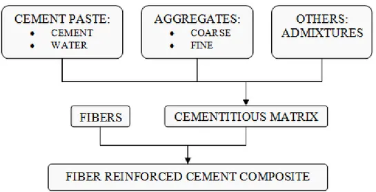
Figure I-1 : Composite model considered as a two component system namely fiber and matrix
... 25
Figure I-2 : Main fiber characteristics in fiber reinforced concrete [Naaman, A.E., 2008]... 26
Figure I-3 : Different types of steel fibers... 28
Figure I-4 : Different types of synthetic fibers... 30
Figure I-5 : Different types of natural fibers ... 31
Figure I-6 : Typical stress strain curves of cylindrical specimens with and without fibers under compression [F. Bencardino et al, 2008]... 33
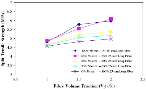
Figure I-7 : Comparison of effect of fiber volume fraction on Dramix I steel fiber reinforced concrete [Zongjin Li et al, 1998]... 34
Figure I-8 : Influence of fiber content on tensile strength [Johnston, C.D. and Coleman, R.A., 1974]... 35
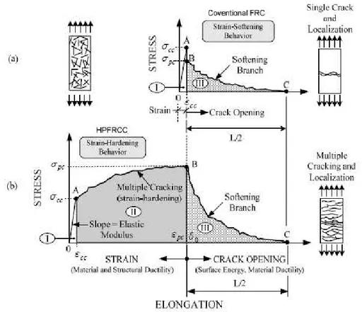
Figure I-9 : Typical stress-strain or stress-elongation curve in tension up to complete separation. (a) Conventional strain-softening FRC composite. (b) Strain-hardening FRC composite or HPFRCC [Naaman, A.E., 2008] ... 35
Figure I-10 : Mechanical response of cement-based composites under uniaxial tension: a) σc– εc and σc–w diagrams of ordinary concretes; b) σc–ε and σc–w diagrams of FRC with low fiber volume fractions (Vf <1%); c) σc–ε and σc–w diagrams of HPFRCC and of FRC with high fiber volume fractions (Vf > 2%) [Alessandro P. F. et al, 2009] ... 36
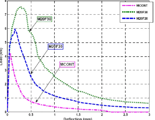
Figure I-11 : PC and SFRC typical experimental load–deflection curves [F. Bencardino et al, 2009]... 38
Figure I-12 : Variation of flexural strength with respect to fiber volume ratio [Su-Tae Kang et al, 2010]... 38
Figure I-13 : Effect of fiber aspect ratio on the load carrying capacity of FRC in flexure [R. Hameed et al, 2009] ... 39
Figure I-14 : (a) reinforced concrete beam without steel fibers, (b) reinforced concrete beam containing steel fibers [Gustavo J. Parra-Montesinos, 2006]... 41
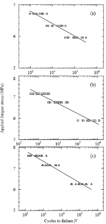
Figure I-15 : Normalized shear stress versus deflection behaviour for reinforced concrete beams with and without steel fiber reinforcement tested at the University of Michigan [Parra-Montesinos, G. et al, 2006] ... 42 Figure I-16 : Details of test beams [Yoon-Keun K. et al, 2002] ... 44 Figure I-17 : Typical force-deflection histories [Yoon-Keun K. et al, 2002] ... 44 Figure I-18 : Cross-sectional dimensions and conventional steel reinforcement of the tested beams [C. E. Chalioris and C. G. Karayannis, 2009]... 47 Figure I-19 : Experimental curves of the beams of group P (without conventional steel reinforcement) [C. E. Chalioris and C. G. Karayannis, 2009] ... 47 Figure I-20 : Experimental curves of the beams of group L (with longitudinal bars) [C. E. Chalioris and C. G. Karayannis, 2009] ... 48 Figure I-21 : Experimental curves of the beams of group R (conventionally reinforced beams with longitudinal bars and stirrups) [C. E. Chalioris and C. G. Karayannis, 2009]... 48 Figure I-22 : S-N relationships for steel fiber reinforced concrete 50% 50 mm+50% 25 mm long fibers based on applied fatigue stress as percentage of static flexural stress.Vf =1.0%; (b)
Vf =1.5%; (c) Vf = 2.0% [Singh S.P. et al, 2006] ... 51
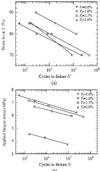
Figure I-23 : S-N relationships for steel fiber reinforced concrete 50% 50 mm+50% 25 mm long fibers based on actually applied maximum fatigue stress. (a) Vf =1.0%; (b) Vf =1.5%;
(c) Vf = 2.0% [Singh S.P. et al, 2006] ... 52
Figure I-24 : Comparison of S-N relationships for steel fibrous concrete based on (a) stress as percentage of static flexural stress and (b) actually applied fatigue stress [Singh S.P. et al, 2006]... 53 Figure I-25 : Compressive and splitting tensile strength of different concrete batches [Wu Yao et al, 2003]... 57 Figure I-26 : Flexure stress versus deflection plots for HyFRC [Wu Yao et al, 2003]... 57 Figure I-27 : Typical Load-deflection plot for hybrid fiber concretes [A. Sivakumar and M. Santhanam, 2007]... 59 Figure I-28 : Flexural strength of various hybrid fiber concretes [A. Sivakumar and M. Santhanam, 2007]... 59
Santhanam, 2007]... 60 Figure I-30 : Compressive strength of fibrous concrete with mixed aspect ratio of fibers at different fiber volume fractions [Y. Mohammadi et al, 2008]... 62 Figure I-31 : Split tensile strength of fibrous concrete with mixed aspect ratio of fibers at different fiber volume fractions [Y. Mohammadi et al, 2008]... 62 Figure I-32 : Static flexural strength of fibrous concrete with mixed aspect ratio of fibers at different fiber volume fractions [Y. Mohammadi et al, 2008]... 63 Figure I-33 : Classes of applications of fiber reinforced cement composites [Naaman, A.E., 2008]... 65 Figure I-34 : Mechanical response of lightly reinforced concrete beams with and without steel fibers [B. Chiaia et al, 2009] ... 66 Figure I-35 : Crack pattern of reinforced concrete beams with and without steel fibers [Vandewalle L., 2000]... 67 Figure I-36 : Mean crack width, test results [Vandewalle L., 2000]... 68 Figure I-37 : Design assumption of singly reinforced concrete beam containing steel fibers [Henager, C. H., and Doherty, T. J., 1976] ... 69 Figure I-38 : Design assumptions for analysis of single reinforced concrete beam [G. Campione, 2008] ... 71 Figure I-39 : Stress-Strain distribution in T-Beam [Ramzi B. et al, 1999] ... 74 Figure I-40 : Modelling of the perturbed area around the micro-crack [from P. Casanova and P. Rossi, 1997] ... 76 Figure I-41 : Stress and strain distribution in cracked section [P. Casanova and P. Rossi, 1997]
... 76 Figure I-42 : Crack geometry relative to the shear behaviour of a rectangular SFRC with classical longitudinal reinforcement [P. Casanova and P. Rossi, 1997] ... 77 Figure I-43 : Failure mechanism relative to a crack block under concentrated loads [P. Casanova and P. Rossi, 1997] ... 79
Figure I-44 : Stress-strain direct tensile test for RFC, experiments (dots) and curves (modelling) [G. camps et al, 2008]... 89 Figure I-45: Matrix material and discrete fibres are merged to obtain a numerical fibre reinforced concrete [F.K.F. Radtke et al, 2010]... 90 Figure I-46 : Development of a simplified mechanical model for FRC composites [F.K.F. Radtke et al, 2010] ... 91 Figure I-47: Mechanical representation of cracked domain bridged by fiber represented by fiber forces [F.K.F. Radtke et al, 2010] ... 92 Figure I-48: Superposition procedure of solving Ktip [J. Zhang and V.C. Li, 2004] ... 93
Figure I-49 : (a) Testing setup and beam cross section; and (b) alternate bending supports [L. Daniel and A. Loukili, 2002] ... 95 Figure I-50 : Dissipated energy versus normalized deflection [L. Daniel and A. Loukili, 2002]
... 96 Figure I-51 : Load setup and joint details [Craig, R et al, 1984]... 97 Figure I-52 : Improvement in joint seismic behaviour due to steel fibers [Craig, R et al, 1984]
... 98 Figure I-53 : Design of original and ½-scale joints [Z. Bayasi and M. Gebman, 2002]... 99 Figure I-54 : Testing setup and loading regime [Z. Bayasi and M. Gebman, 2002]... 99 Figure I-55 : Average energy absorption capacity for joint samples [Z. Bayasi and M. Gebman, 2002] ... 100 Figure I-56 : Structural forms investigated [G. Kotsovos et al, 2007]... 101 Figure I-57 : Experimental Setup [G. Kotsovos et al, 2007]... 101 Figure II-1: FibraFlex fibers... 109 Figure II-2: Dramix fibers ... 109 Figure II-3: Compressive strength... 111 Figure II-4: Percentage change in compressive strength of fibered concretes compared to control concrete (without fibers) ... 112 Figure II-5: Test Specimen (Notched) for direct tension tests (dimensions are in mm) ... 113
Figure II-7 : A) Tensile stress versus CMOD curves of CONT; B) Blow up of curves of CONT up to 0.2 mm; C) Tensile stress versus CMOD curves of F20; D) Blow up of curve of F20 up to 0.2 mm ... 115 Figure II-8 : A) Tensile stress versus CMOD curves of D20; B) Blow up of curves of D20 up to 0.2 mm; C) Tensile stress versus CMOD curves of F20D20; D) Blow up of curve of F20D20 up to 0.2 mm ... 116 Figure II-9 : A) comparison of tensile stress versus CMOD curves of all compositions; B) Blow up of all curves up to 0.2 mm ... 117 Figure II-10 : General trend curve of CONT in direct tension... 119 Figure II-11 : General trend curve of F20 in direct tension ... 119 Figure II-12 : General trend curve of D20 in direct tension... 120 Figure II-13 : General trend curve of F20D20 in direct tension ... 120 Figure II-14: Fracture surface of specimens tested in direct tension ... 121 Figure II-15: Specimen details (flexural test) ... 124 Figure II-16: Testing setup for flexural test ... 124 Figure II-17 : CMOD versus Load curves ... 125 Figure II-18 : Blow up of figure II-17 up to 1 mm CMOD ... 125 Figure II-19 : CMOD versus Load curves ... 126 Figure II-20 : Blow up of figure II-19 up to 1 mm CMOD ... 126 Figure II-21 : Load Deflection curves ... 127 Figure II-22 : Blow up of figure II-21 up to 1 mm deflection ... 127 Figure II-23 : Load deflection curves... 128 Figure II-24 : Blow up of figure II-23 up to 1 mm deflection ... 128 Figure II-25 : Modulus of rupture ... 129 Figure II-26 : Percentage increase in MOR by the addition of fibers ... 130 Figure II-27 : Residual Flexural Tensile Strength (RFTS)... 131
Figure II-28 : Residual Flexural Tensile Strength (RFTS)... 133 Figure II-29 : Flexural Toughness (FT) up to 4 mm deflection ... 134 Figure II-30 : Synergy assessment in terms of MOR... 137 Figure II-31 : Synergy assessment in terms of flexural toughness ... 137 Figure II-32 : Synergy assessment in terms of RFTS (F20D20)... 137 Figure II-33 : Synergy assessment in terms of RFTS (F40D40)... 138 Figure II-34 : Fracture surface of specimen with high bond FibraFlex fibers (left) and with low bond Dramix fibers (right) ... 139 Figure II-35 : Cross section and reinforcement details of test specimen ... 142 Figure II-36 : Test setup and measurement scheme ... 143 Figure II-37 : CMOD versus moment curves... 144 Figure II-38 : Deflection versus moment curves... 144 Figure II-39 : Cracking and ultimate moment... 145 Figure II-40 : Percentage increase in cracking and ultimate moment of reinforced fibrous concrete beams compared to control reinforced concrete beam ... 146 Figure II-41 : Evolution of CMOD with moment (up to Mult attained by RCB-CONT) ... 147
Figure II-42 : Evolution of deflection with moment (up to Mult attained by RCB-CONT) ... 147
Figure II-43 : load-Deflection trend curves of RC beams with and without fibers... 148 Figure II-44 : Cracking of RC beams with and without fibers... 148 Figure II-45 : Micro-cracking and action of fibers ... 150 Figure II-46 : Macro-cracking and action of fibers ... 151 Figure II-47 : Linear stress strain distribution just before cracking ... 152 Figure II-48 : Stress strain distribution of reinforced concrete ... 153 Figure II-49 : Stress strain distribution of reinforced fibrous concrete... 154 Figure II-50 : Test specimen ... 160 Figure II-51 : Location of strain gages on steel bar ... 161 Figure II-52 : Location of strain gages on concrete ... 162
Figure II-54 : Measurement of axial deformation using LVDT... 163 Figure II-55 : Load-Deformation response of RCP-CONT (axial strain is in µm/m)... 164 Figure II-56 : Load-Deformation response of RCP-F20 (axial strain is in µm/m) ... 164 Figure II-57 : Load-Deformation response of RCP-D20 (axial strain is in µm/m)... 165 Figure II-58 : Load-Deformation response of RCP-F20D20 (axial strain is in µm/m) ... 165 Figure II-59 : Loading history at different stages ... 166 Figure II-60 : Tensile response of axial tension member [Bischoff P. H., 2003] ... 167 Figure II-61 : Effect of metallic fibers on stiffness ... 167 Figure II-62 : Local strain at different section of steel bar (RCP-CONT) ... 169 Figure II-63 : Location of transverse crack ... 169 Figure II-64 : Local strain at different section of steel bar (RCP-F20)... 170 Figure II-65 : Comparison of steel strain before cracking at mid section... 171 Figure II-66 : Local strain at different section of steel bar (RCP-D20) ... 172 Figure II-67 : Local strain at different section of steel bar (RCP-F20D20) ... 172 Figure II-68 : Surface strain versus axial load (RCP-CONT) ... 174 Figure II-69 : Surface strain versus axial load (RCP-F20)... 174 Figure II-70 : Surface strain versus axial load (RCP-D20) ... 175 Figure II-71 : Surface strain versus axial load (RCP-F20D20)... 175 Figure II-72 : Comparison of concrete surface strain before cracking... 176 Figure II-73 : Crack development in axial tensioned member... 178 Figure II-74 : Pull-out test specimen... 180 Figure II-75 : Mechanism of bond resistance in confined concrete [P. Soroushian et al, 1994]
... 181 Figure II-76 : Schematic diagram of test specimen... 183 Figure II-77 : Pull-out test specimen details ... 184
Figure II-78 : Setup for Pull-out test ... 185 Figure II-79 : Bond stress-slip behaviour with and without confinement... 186 Figure II-80 : Comparison of local bond stress-slip response of different composites... 187 Figure II-81 : Maximum bond stress normalised by compressive strength ... 188 Figure II-82 : Definition of toughness... 189 Figure II-83 : Toughness normalized by fc’ (N-mm/MPa) ... 190
Figure II-84 : Fiber bond crack arrest mechanism [M. H. Harajli et al, 1995] ... 190 Figure II-85 : Normal and shear stresses on the main steel bar ... 191 Figure II-86 : Crack arrest mechanism by FibraFlex fibers ... 192 Figure II-87 : Shearing-off of concrete matrix between steel bar’s lugs ... 192 Figure III-1 : Dimensions and reinforcement details of tests specimens ... 203 Figure III-2 : Pan type concrete mixer ... 204 Figure III-3 : Steel cage used to construct beam ... 204 Figure III-4 : Mould used to cast beams ... 205 Figure III-5 : Method of external vibration ... 206 Figure III-6 : Model of testing setup in CASTEM... 207 Figure III-7 : Some model results ... 208 Figure III-8 : Schematic illustration of testing setup... 209 Figure III-9 : Experimental setup (test in progress) ... 209 Figure III-10 : History of the displacement controlled reverse cyclic loading ... 210 Figure III-11 : Displacement measurement scheme... 210 Figure III-12 : Cracking pattern of tested beams ... 212 Figure III-13 : Severe spalling of concrete cover in RC beam without fibers ... 212 Figure III-14 : Spalling of concrete cover in reinforced fibrous concrete beams ... 213 Figure III-15 : Load –Displacement hysteresis loops (cont, F20, D20, and B6-F20D20) ... 215
Figure III-17 : Load-Displacement envelope curves... 217 Figure III-18 : Load-Displacement envelope curve ... 218 Figure III-19: rough surface showing casting direction ... 219 Figure III-20 : Distribution of fibers in two directions in the mould ... 219 Figure III-21 : Typical loading cycle for a structural element ... 223 Figure III-22 : Average Dissipated Energy (ADE) in kN-mm... 226 Figure III-23 : Effectiveness of FibraFlex fibers on energy dissipation ... 226 Figure III-24 : Effectiveness of Dramix fibers on energy dissipation... 227 Figure III-25 : Comparison of effectiveness of FibraFlex and Dramix fibers on energy dissipation capacity of RC beam at dosage of 20 kg/m3... 228 Figure III-26 : Comparison of effectiveness of FibraFlex and Dramix fibers on energy dissipation capacity of RC beam at dosage of 40 kg/m3... 228 Figure III-27 : synergy assessment for B6-F20D20 in terms of dissipated energy... 230 Figure III-28 : Synergy assessment for B6-F40D40 in terms of dissipated energy... 230 Figure III-29 : Comparison of dissipated energy of B6-F40 and B6-F20D20... 231 Figure III-30 : Comparison of energy dissipation of B6-D40 and B6-F20D20... 232 Figure III-31 : Evaluation of equivalent viscous damping... 235 Figure III-32 : Equivalent Viscous Damping (EVD) in a typical loading cycle... 236 Figure III-33 : Equivalent viscous damping (B6-cont, B6-F20 and B6-F40) ... 236 Figure III-34 : Equivalent viscous damping (B6-cont, B6-D20 & B6-D40) ... 237 Figure III-35 : Equivalent viscous damping (B6-cont, B6-F20 and B6-D20) ... 238 Figure III-36 : Equivalent viscous damping (B6-cont, B6-F40 and B6-D40) ... 239 Figure III-37 : Equivalent viscous damping (B6-F40 and B6-F20D20) ... 239 Figure III-38 : Equivalent viscous damping (B6-D40 and B6-F20D20) ... 240 Figure III-39 : Comparison of the reinforcement... 242 Figure III-40 : Load-Displacement hysteresis loops of B8-cont... 243
Figure III-41 : Comparison of energy dissipation at 1 mm displacement... 244 Figure III-42 : Comparison of energy dissipation at 2 mm displacement... 244 Figure III-43 : Comparison of energy dissipation at 3 mm displacement... 245 Figure III-44 : Comparison of energy dissipation at 4mm displacement... 245 Figure III-45 : Comparison of energy dissipation at 5mm displacement... 246 Figure III-46 : Comparison of energy dissipation at 8 mm displacement... 246 Figure III-47 : Comparison of energy dissipation at 10 mm displacement... 247 Figure IV-1 : Pre and post cracking behaviour of FRC in direct tension... 255 Figure IV-2 : Equivalent one dimensional idealized damage model [A. Sellier et al, 2010]. 256 Figure IV-3 : Idealised representative elementary volume of concrete damage by an oriented micro-crack [A. Sellier et al, 2010]... 259 Figure IV-4 : Idealized representative elementary volume of concrete damage by an orthotropic micro-cracking [Sellier A. et al, 2010] ... 261 Figure IV-5 : Uni-axial tensile behaviour modelling (softening part given for three possible element sizes) [A. Sellier et al, 2010] ... 263 Figure IV-6 : Dramix fiber bridging the crack ... 267 Figure IV-7 : Damage evolution due to fiber pull-out from the matrix ... 268 Figure IV-8 : Different parameters of model for FRC with sliding fibers ... 269 Figure IV-9 : Stress-strain curve for plain concrete and FRC containing FibraFlex fibers ... 270 Figure IV-10 : Finite element mesh of specimen in direct tension test simulation... 271 Figure IV-11 : Comparison of experimental and model Stress versus CMOD curves in direct tension (all compositions) ... 273 Figure IV-12 : Localised crack in finite element mesh (control concrete) ... 274 Figure IV-13 : Localised crack in finite element mesh (F20) ... 274 Figure IV-14 : Localised crack in finite element mesh (D20) ... 275 Figure IV-15 : Localised crack in finite element mesh of F20D20 (HyFRC) ... 275
tests simulation... 277 Figure IV-17 : Comparison of Load-Deflection and Load-CMOD curves of control concrete in three point bending test (Model and experimental results) ... 278 Figure IV-18 : Boundary conditions in 3PBT (experiment and simulation)... 278 Figure IV-19 : Crack localisation and propagation (control concrete in 3PBT) ... 279 Figure IV-20 : Comparison of Load-Deflection and Load-CMOD curves of F20 in three point bending test (Model and experimental results) ... 280 Figure IV-21 : Crack localisation and propagation (F20 in 3PBT)... 280 Figure IV-22 : Comparison of Load-Deflection and Load-CMOD curves of D20 in three point bending test (Model and experimental results) ... 281 Figure IV-23 : Crack localisation and propagation (D20 in 3PBT) ... 281 Figure IV-24 : Comparison of Load-Deflection and Load-CMOD curves of F20D20 in three point bending test (model and experimental results)... 282 Figure IV-25 : Crack localisation and propagation (F20D20 in 3PBT)... 282 Figure IV-26 : Method adapted to model interface between steel bar and concrete... 284 Figure IV-27 : Global stiffness of two equivalent systems ... 284 Figure IV-28 : Three dimensional finite element mesh of pullout test specimen ... 286 Figure IV-29 : Strain calculation from the slip value... 288 Figure IV-30 : Pull-out test simulation (model fitting) ... 288 Figure IV-31 : Damage evolution at interface of steel bar and concrete in pullout test ... 289 Figure IV-32 : Three dimensional finite element mesh of element subjected to pure tension
... 291 Figure IV-33 : Comparison of load versus global axial deformation curves (model and experiment results – RC prism subjected to pure tension)... 292 Figure IV-34 : Damage evolution and crack localisation in finite element mesh of prism subjected to pure tension ... 293 Figure IV-35 : Finite element mesh of reinforced concrete beam ... 294
Figure IV-36 : Comparison of experimental and modelling results for reinforced concrete beam in terms of load-deflection and load-CMOD curves ... 295 Figure IV-37 : Damage and localised crack in finite element mesh of RCB-cont... 295 Figure IV-38 : Comparison of experimental and modelling results for fibrous reinforced concrete beam (RFCB – F20) in terms of load-deflection and load-CMOD curves... 296 Figure IV-39 : Comparison of experimental and modelling results for fibrous reinforced concrete beam (RFCB – D20) in terms of load-deflection and load-CMOD curves ... 297 Figure IV-40 : Comparison of experimental and modelling results for fibrous reinforced concrete beam (RFCB – F20D20) in terms of load-deflection and load-CMOD curves... 297
Table I-1: Summary of test program [Yoon-Keun K. et al, 2002]... 43 Table I-2: Different concrete batches [Wu Yao et al, 2003] ... 56 Table I-3: Dosage of different fibers used in the study [A. Sivakumar and M. Santhanam, 2007]... 58 Table I-4: steel fibrous concrete mixes [Y. Mohammadi et al, 2008]... 61 Table I-5 : Properties of fibers investigated [Banthia N. and Gupta R., 2004]... 64 Table II-1: Concrete constituents in kg/m3... 108 Table II-2: Characteristics of fibers investigated in this study... 109 Table II-3: Different Concrete Mixtures tested in compression ... 110 Table II-4: Different Concrete Mixtures for Direct Tensile Tests ... 113 Table II-5 : Composites Tested in Flexure... 123 Table II-6 : Fiber contents in different concrete mixtures... 142 Table II-7: Cracking and Ultimate Moments for all compositions ... 143 Table II-8 : analytical and experimental moment capacities of reinforced fibrous concrete beams... 156 Table II-9 : Fiber contents in different concrete mixtures... 159 Table II-10: concrete mixtures for pullout tests ... 184 Table III-1 : Details of Beams... 202 Table III-2 : Frequency of cyclic loading... 210 Table III-3: Energy Dissipated by the tested Beams, kN-mm ... 224 Table III-4 : Average value of Dissipated Energy in three cycles, kN-mm ... 225 Table IV-1 : Model Parameters and their values used in numerical simulation ... 272 Table IV-2 : parameters of damage model for massive concrete... 287 Table IV-3 : Parameters for model of interface bond element... 287
GENERAL INTRODUCTION
Cementitious materials are characterised by low tensile strength, low strain capacity and low fracture toughness: they are brittle materials. Reinforcement in the form of continuous steel bars and stirrups is used to resist imposed tensile and shear stresses in reinforced concrete which renders it a usable structural materia. In the last five decades, another kind of reinforcement has been used to overcome the brittleness, namely discontinuous and randomly distributed fibers, producing a new structural material known as fiber reinforced concrete with improved strength, ductility and durability. The term Fiber Reinforced Concrete (FRC) is defined as concrete made of hydraulic cements containing fine and coarse aggregates and discontinuous discrete fibers [ACI Committee 544, 1997]. It is important to recognize that, in general, fiber reinforcement is not a substitute for conventional reinforcement. The role of these two types of reinforcement is different in concrete; continuous steel bars are used to increase the tensile and shear capacities of concrete while the primary reason for addition of discontinuous fibers to the concrete matrix is to improve the post cracking response by controlling the crack opening and propagation. FRC has been widely used in a variety of civil engineering applications including pre-cast structural elements, shotcrete, machine foundation, hydraulic structures, pavements, seismic structures, overlays and crash barriers. Mechanical properties of FRC are highly dependant on material, geometry, shape, physical/chemical properties, mechanical properties and dosage of fibers. These also depend on the properties of the concrete in which they are incorporated. Different types of fiber materials that have been tested in the past include natural organic (such as jute, cellulose, bamboo, etc); natural mineral (such as asbestos, rock-wool, etc.); and man made materials (such as glass, steel, carbon, polymer, synthetic, etc.). Physical and chemical properties of fibers such as surface roughness, density, non-reactivity with cement, etc have also important role on the effectiveness of fiber in the matrix. Research studies in the past have shown that the mechanical properties of fibers such as tensile strength, modulus of elasticity, stiffness, ductility, etc are also very important to get successful composite. Once a fiber is selected, infinite combinations of geometric properties related to their cross-sectional shape, length, diameter or equivalent diameter and surface deformation is selected. For the same fibers, these geometrical properties have been reported to have significant influence on the mechanical properties of the composite. Another important parameter for degree of improvement in any of the mechanical properties of FRC is the fiber contents (refered to as
General Introduction
dosage). Studies have shown that the improvement in the mechanical properties of composite is directly related to the fiber contents in the matrix. It is always necessary to find out an optimal dosage of each type of fiber taking into account the properties of fresh composite notably the effects of the fibers on compactness and workability.
In FRC, fibers can be effective in arresting cracks at both micro and macro levels. In most cases, FRC involves the use of a single fiber type. This implies that a given fiber can provide reinforcement only at one level and within a limited range of strain, crack opening or deflection. For an optimal response, therefore, hybridization (mixing) of different types of fibers may be done to produce hybrid fiber reinforced concrete (HyFRC). The use of two or more types of fibers in a suitable combination may potentially not only improve the overall properties of concrete, but may also result in performance synergy [Banthia N. & Gupta R. 2004; Banthia N. & Sappakittipakorn M. 2007]. Synergy is the phenomenon where acting of two or more subjects together leads to a better result than the sum of actions of the same subjects independently of each other [Vandewalle L. 2007].
For the structures subjected to seismic loading, there is always need for high energy absorbing materials that will mitigate the hazards. While the influence of fibers on the pre-cracking behaviour is only marginal, the potency of fiber addition becomes apparent after the brittle concrete matrix has cracked. In the post-cracking stage, fibers bridge the cracks and cause important increase in the ductility and toughness (energy absorption capacity) of the composite. The use of fibers with different properties to increase the toughness of cement based composite and comparing energy absorption capacities of composites with different fibers may provide useful information about fiber reinforced cement based composites to be used in seismically active regions.
Energy dissipation capacity has been used as a criterion to evaluate structural member to withstand cyclic inelastic loading [S. N. Sinha and K. S. Naraine, 1991]. The earthquakes release tremendous amount of energy. This energy propagates in all directions and enters a structure as ground motion. The seismic energy which is introduced into the structure must be dissipated within the structure. The structure should go to the inelastic range of stresses and strains producing cracking and plastic hinge formation to dissipate energy in case of heavier earthquake. An earthquake resistant structure should dissipate energy associated with various levels of damage in the structural system, but collapse should not occur, what is more, after
the earthquake, damage should be economically feasible to repair [E. Atimtay and R. Kanit, 2006].
Under reverse cyclic loading, concrete is subjected to a more severe tensile damage of concrete and bond deterioration since it comes under tension and compression alternatively. The severe concrete damage due to alternate loading induces a loss in both maximum load bearing capacity and ductility.
To enhance the structural performance under seismic loading, use of steel fibers has been the subject of many research projects in the recent past [A. Filiatrault et al, 1995, H. Kimura et al, 2007]. The improvements involved the increase of dissipated energy and reduced strain magnitude [L. Daniel and A. Loukili, 2002].
In October 2005, Earthquake in Pakistan (7.4 on Richter scale) caused 80,000 deaths and about 70,000 people were seriouly injured (most of them were children and women). Many houses were completely destroyed. Inspection of the earthquake affected sites revealed that main causes of the severe damages to infrastructures were the poor materials of construction and design of structures without seismic design considerations.
In Pakistan, usual practice is to use normal strength reinforced concrete as a construction material. The present research work aims to study the possibility of using fibers to improve the mechanical behaviour of normal strength reinforced concrete structural elements to withstand seismic events and to avoid collapse of structures. The financial support to the research student was provided by the Higher Education Commission (HEC-Government of Pakistan) for the whole period of research work under the scholarships scheme entitled “Overseas scholarships for PhD studies- 2006”.
Objectives and Scope
The present work on fiber reinforced concrete is categorised under the following topics:
1. Choice of fibers to be used
2. Characterisation of metallic fiber reinforced concrete
General Introduction
4. Reverse cyclic flexural tests on reinforced fibrous concrete beams
5. Numerical modelling of the mechanical behaviour of reinforced fibrous concrete elements
In this study two different types of metallic fibers have been used. The objectives that fall under the category of characterisation of fiber reinforced concrete are:
To examine the effect of each type of metallic fibers on the mechanical properties of fiber reinforced concrete (such as compressive strength, tensile strength and flexural behaviour).
To study the effect of fiber hybridization on the mechanical properties fiber reinforced concrete composites.
The followings objectives fall under the category of characterisation of reinforced fibrous concrete:
From the structural point of view, two aspects are important; firstly, to investigate the ability of metallic fibers to confine the concrete in column-beam joint region by performing pull-out tests, and secondly, to study the effect of metallic fiber addition on the cracking behaviour of reinforced concrete (RC) elements subjected to pure axial tensile loading.
To investigate the moment capacity of concrete beams reinforced with conventional reinforcement and metallic fibers subjected to static flexural loading.
To study the effect of metallic fibers both in mono and hybrid forms on the deflection and crack width control in reinforced concrete beams subjected to static flexure load.
The objective that falls under the fourth category is:
To investigate the influence of metallic fibers on load bearing capacity, energy dissipation and equivalent viscous damping of reinforced fibrous concrete beams subjected to reverse cyclic flexural loading.
The objective that falls under the fifth category is:
To propose a numerical model able to predict the mechanical behaviour of reinforced fibrous concrete.
Thesis Organization
This thesis includes five chapters and is organised as follows:
Chapter 1 is about the literature survey and has been divided into thirteen parts. The first part of the literature review gives a historical overview of the concrete in the past. The second part provides some information about earthquakes. Part three and part four present reviews of fundamental concept and design consideration in seismic design of concrete structures. The fifth part of this chapter highlights some basic properties of construction materials to be used in seismic resistant structures. In Parts six and seven, a brief introduction to fiber reinforced concrete (FRC) composites and different types of fibers used in the past is given. Part eight deals with reviews of previous research studies on FRC composites to determine their static mechanical properties. Part nine of this chapter gives brief introduction about hybrid fiber reinforced concrete (HyFRC) and discusses some research studies carried out on HyFRC in recent past. Parts ten and eleven describe briefly the mechanical behaviour of reinforced fibrous concrete beams and presents some analytical and numerical models available in the literature to predict their mechanical behaviour. The twelfth part reviews previous research work on the seismic application of FRC composites. Finally, this chapter ends with conclusing remarks.
Chapter 2 describes the experimental investigation carried out to mechanically characterise the FRC composites used in this study. This chapter is divided into two parts: in the first part, details of different mechanical tests performed on mono and hybrid fiber reinforced concrete composite and their results are presented and discussed. The second part presents the results of different mechanical tests performed on reinforced fibrous concrete elements.
Chapter 3 describes the experimental investigation carried out to study the mechanical behaviour of reinforced fibrous concrete beams subjected to reverse cyclic flexural loading. Details of experimental setup, test specimen, casting of test specimen and testing procedure (loading history) are presented. From the results of the experiments performed, influence of
General Introduction
two types of metallic fibers on load carrying capacity, energy dissipation and equivalent viscous damping of the RC beams has been investigated.
Chapter 4 addresses numerical modelling of fiber reinforced concrete. First, the material model for the plain concrete proposed by [A. Sellier et al, 2010] is discussed, and then the constitutive behaviour law for the action of metallic fibers in the matrix is presented. The models of plain concrete and metallic fibers are then combined to predict the mechanical behaviour of fiber reinforced concrete composites. Besides the numerical model for the FRC, a simplified approach to model the interface between steel reinforcement and concrete in case of reinforced concrete element has also been proposed in this chapter. The implementation and testing of the proposed model for FRC composites and simplified approach to model reinforced concrete to verify their capability and applicability in capturing material behaviour in different mechanical tests is also described in detail in this chapter. Finally, the comparison of experimental and model results is presented.
Based on the results of experimental investigation and modelling work, chapter 5 provides summary, general conclusions and recommendations for the future work.
INTRODUCTION GENERALE
Les matériaux à base cimentaire sont caractérisés par une faible résistance à la traction, et présentent une capacité de déformation et une ténacité réduites qui en font des matériaux fragiles. Pour les applications structurales de ces matériaux où règnent des sollicitations de traction et de cisaillement, le renforcement continu sous forme de barres et de cadres d'acier est couramment utilisé depuis près de 120 ans. Au cours des cinq dernières décennies, une autre sorte de renforcement, discontinu, a été introduit pour surmonter la fragilité et améliorer la résistance, la ductilité et la durabilité, sous forme de fibres réparties aléatoirement dans le matériau. Le matériau cimentaire ainsi produit est appelé béton renforcé de fibres (BRF). Ce dernier est défini comme un béton fabriqué à partir de ciments hydrauliques, de granulats fins et grossiers et de fibres discontinues [ACI Committee 544, 1997]. Il est important de noter que le renforcement par des fibres n'est généralement pas un substitut au ferraillage classique. Le rôle joué par ces deux types de renforcement est différent dans le béton. Le ferraillage classique améliore la résistance à la traction et au cisaillement du béton, tandis que la principale raison de l'ajout de fibres discontinues dans la matrice cimentaire est l'amélioration de la réponse post-fissuration par contrôle de l’ouverture de fissure et sa propagation. Le BRF a été largement utilisé pour une variété d'ouvrages de génie civil, comprenant les éléments structuraux préfabriqués, les coques en béton projeté, les fondations spéciales pour certaines machines, les ouvrages hydrauliques, les trottoirs et enfin les structures parasismiques.
Les propriétés mécaniques du BRF sont fortement dépendantes des caractéristiques des fibres (nature, géométrie, forme, propriétés physico-chimiques et propriétés mécaniques) et de leur dosage dans le béton. Elles dépendent aussi des propriétés du béton dans lequel les fibres sont incorporées. Différents types de fibres ont été testés dans la littérature : des fibres organiques naturelles (comme le jute, la cellulose, le bambou, etc.), des fibres minérales naturelles (comme l'amiante, la laine de roche, etc.) et des fibres en matière industrielle (fibres de verre, d'acier, de carbone, de polymères et synthétiques, etc.). Les propriétés physico-chimiques des fibres (telles que la rugosité de surface, la densité, la non-réactivité avec les hydrates du ciment, etc.) ont un rôle important sur l'efficacité de la fibre dans la matrice. Les études de recherche dans le passé ont également montré que les propriétés mécaniques des fibres (telles que la résistance à la traction, le module d'élasticité, la rigidité, la ductilité, etc.) ont un effet significatif sur le comportement du composite. Une fois que le type de fibre est sélectionné, une large variété de caractéristiques géométriques liées à sa forme transversale, à sa longueur,
General Introduction
à son diamètre et à la surface de déformation est disponible. Ces caractéristiques, qui ont pour un même type de fibre une influence significative sur les propriétés mécaniques du composite, doivent à leur tour être sélectionnées. Un autre paramètre important, jouant sur le degré d'amélioration des propriétés mécaniques du BRF, est la teneur en fibres. Des études ont montré que l'amélioration des propriétés mécaniques du composite est directement liée à la teneur en fibres dans la matrice, et il est toujours nécessaire de trouver un dosage optimal de chaque type de fibre en tenant compte notamment de l'effet des fibres sur la compacité et la maniabilité du béton à l’état frais.
Les fibres peuvent être efficaces pour ponter les fissures aussi bien au niveau micro qu'au niveau macroscopique. Dans la plupart des cas, un seul type de fibre est présent dans le BRF, ce qui restreint l'efficacité de l'ajout à une gamme limitée de déformation, et d’ouverture de fissure. Pour une réponse optimale, il convient par conséquent de recourir à un mélange hybride de différents types de fibre. L'utilisation de plusieurs types de fibres dans une combinaison appropriée, comprenant généralement deux types de fibre, peut non seulement améliorer l'ensemble des propriétés du béton, mais il peut également en résulter une performance synergétique [N. Banthia & R. Gupta 2004; Banthia N. & M. Sappakittipakorn 2007]. La synergie apparaît lorsque le mélange de fibres conduit à des effets bénéfiques supérieurs à la somme des effets bénéfiques de chacun des types de fibre [Vandewalle L. 2007].
Dans les applications parasismiques, le besoin se porte sur des matériaux et des systèmes structuraux présentant une capacité de dissipation d'énergie élevée. Les mouvements imposés par le sol sur les structures lors de tremblements de terre y injectent une énorme quantité d'énergie, qui doit être dissipée par incursion des déformations en zone plastique de comportement, et simultanément par l'endommagement des matériaux constitutifs, sous la contrainte de non effondrement et, si possible, de réparation économiquement envisageable [E. Atimtay et R. Kanit, 2006].
Bien que l'influence des fibres sur le comportement pré-fissuration soit marginal, l'ajout de fibres présente un potentiel intéressant pour les applications parasismiques. Dans la phase post-fissuration, au niveau microscopique, les fibres peuvent en effet retarder la localisation de la fissuration, tandis qu'au niveau macroscopique elles peuvent assurer un pontage avant de se plastifier, ce qui induit une augmentation de la dissipation d'énergie par fissuration, puis par plastification : la ductilité et la ténacité du composite s'en trouvent ainsi améliorées.
![Figure I-7 : Comparison of effect of fiber volume fraction on Dramix I steel fiber reinforced concrete [Zongjin Li et al, 1998]](https://thumb-eu.123doks.com/thumbv2/123doknet/2224747.15324/68.892.216.686.117.462/figure-comparison-effect-fraction-dramix-reinforced-concrete-zongjin.webp)
![Figure I-12 : Variation of flexural strength with respect to fiber volume ratio [Su-Tae Kang et al, 2010]](https://thumb-eu.123doks.com/thumbv2/123doknet/2224747.15324/72.892.277.623.489.836/figure-variation-flexural-strength-respect-fiber-volume-ratio.webp)
![Figure I-25 : Compressive and splitting tensile strength of different concrete batches [Wu Yao et al, 2003]](https://thumb-eu.123doks.com/thumbv2/123doknet/2224747.15324/91.892.133.779.117.393/figure-compressive-splitting-tensile-strength-different-concrete-batches.webp)