Polymer Blending as a Surface Modification Technique to
Alter the Wettability of Hydrophobic Electrospun Mats
by
Rafael SALLES KURUSU
MANUSCRIPT-BASED THESIS PRESENTED TO ÉCOLE DE
TECHNOLOGIE SUPÉRIEURE IN PARTIAL FULFILLMENT FOR THE
DEGREE OF DOCTOR OF PHILOSOPHY
Ph.D.
MONTREAL, DECEMBER 19, 2016
ÉCOLE DE TECHNOLOGIE SUPÉRIEURE UNIVERSITÉ DU QUÉBEC
© Copyright reserved
It is forbidden to reproduce, save or share the content of this document either in whole or in parts. The reader who wishes to print or save this document on any media must first get the permission of the author.
BOARD OF EXAMINERS
THIS THESIS HAS BEEN EVALUATED BY THE FOLLOWING BOARD OF EXAMINERS
Professor Nicole R. Demarquette, Thesis Supervisor
Mechanical Engineering Department at École de technologie supérieure
Professor Simon Joncas, President of the Board of Examiners
Automated Manufacturing Engineering Department at École de technologie supérieure
Professor Éric David, Member of the jury
Mechanical Engineering Department at École de technologie supérieure
Professor Ricardo Zednik, Member of the jury
Mechanical Engineering Department at École de technologie supérieure
Professor Basil Favis, External Evaluator École Polytechnique de Montréal
THIS THESIS WAS PRESENTED AND DEFENDED
IN THE PRESENCE OF A BOARD OF EXAMINERS AND PUBLIC ON DECEMBER 12, 2016
ACKNOWLEDGMENT
First, I would like to thank Professor Nicole for the opportunity to be the first graduate student to join the group at ÉTS. I will always appreciate the time, guidance and especially the trust and freedom I had to conduct my project and to make my own mistakes and discoveries.
I would also like to express my gratitude to the École de Technologie Supérieure for the generous scholarship I received to pursuit my studies during these four years. I hope I have met the expectations and I also hope that this type of program to support foreign students will continue to exist.
Among people from ÉTS, I would like to thank Professor Éric David for his help throughout the whole project; Professor Sophie Lerouge, whose classes inspired me to change the direction of my project and her students (Mathieu, Audrey, Fatemeh and Jessica) for the help with experiments; Professor Sylvain Cloutier and his students (Jaime, Felipe and Charles) for helping me with film fabrication; Professors Natalia Nuño, Ricardo Zednik and Simon Joncas for agreeing to evaluate this work during exams or defense. I would also like to thank the technicians Radu, Olivier, Nabil, Claude-Daniel and Michel for their practical help.
I would like thank Professor Basil Favis from École Polytechnique for agreeing to evaluate this thesis; Professor Ali Dolatabadi and his student Navid for the high-speed imaging experiments at Concordia University; Patricia at Université de Montréal for the help with AFM experiments and Josianne for all the XPS at Polytechnique.
I would like to express my gratitude to all the students and interns from our research group during this time: Anthony, Camille, Carlos, Chris, Emna, Foued, Marwa, Victor and Zahra. I wish you the best of luck on your path.
I could not forget the people who have made the life in Montreal or elsewhere much more interesting and have helped me to cope with difficult times. Glenn and Odile, for the talks, beers, food, festivals, etc. People from ÉTS that I got to know better outside: Audrey, Fernando, Felipe, Jaime, Oana, Thomas, Rafael, Leice, Julie, Mauricio and Scheyla. All the French-speaking people I bothered during lunch, in special Patrice, Martin, Thibault and Romain. Also, Mary’s friends from Polytechnique and Canarail and all my Brazilian friends for being present even by distance.
A special thanks to my parents, my brother and my sister and all the family for their love and support.
And, of course, I would like to thank Mary for being there, for pushing me when needed, for absolutely everything. And our little one, who, as I write this section, is about to start his journey in this world. Thanks for putting things in perspective, or, as a materials scientist would say, for helping me find the right magnification.
LES MÉLANGES DE POLYMÈRES COMME TECHNIQUE DE TRAITEMENT DE SURFACE POUR ALTÉRER LA MOUILLABILITÉ DES TAPIS ÉLECTROFILÉS
Rafael SALLES KURUSU RÉSUMÉ
Dans cette thèse, l’utilisation des mélanges de polymères comme technique de modification de surface pour contrôler la mouillabilité des tapis électrofilés a été étudiée. Dans la première étape, une matrice hydrophobe (SEBS) a été mélangée avec un copolymère amphiphile (PEO-PPO-PEO) et les résultats ont montré que l'hydrophilisation a été réalisée avec 15% en poids de PEO-PPO-PEO avec une grande ségrégation à la surface. Cependant, cette composition a présenté des propriétés de surface non homogènes. Une analyse microscopique a révélé que la composition à 20% en poids de PEO-PPO-PEO a présenté une morphologie particulière avec des grains interconnectés qui a augmenté la rugosité de la surface des films et des fibres et qui a contribué aux propriétés de surface plus homogènes. Dans l'étape suivante, trois types de copolymères PEO-PPO-PEO avec des poids moléculaires et des contenus de PEO différents ont été utilisés pour hydrophiliser le SEBS. La ségrégation à la surface a augmentée dans les mélanges de SEBS avec des molécules PEO-PPO-PEO plus petites et avec une proportion plus élevée de blocs hydrophobes PPO. L’hydrophilisation a été réalisée avec aussi peu que 5% en poids de PEO-PPO-PEO et la saturation de la surface a également été observée. L'imagerie à grande vitesse et les mesures à effet de mèche ont montré que le temps d'étalement et de remontée capillaire varient grandement en fonction du niveau de la ségrégation et le type de PEO-PPO-PEO utilisé dans les mélanges. La dernière partie de cette thèse est une comparaison des mélanges des polymères hydrophobes soit avec un polymère hydrophile (PEO) ou avec des polymères amphiphiles (PEO-PPO-PEO) pour atteindre l’hydrophilisation. Les résultats ont montré que la présence des blocs PPO avec une faible énergie de surface a augmenté considérablement la ségrégation des polymères PEO-PPO-PEO vers la surface tandis que les mélanges avec PEO pur ont présenté une diminution de PEO dans la surface. De manière surprenante, la ségrégation de PEO-PPO-PEO a continué pendant plusieurs semaines à température ambiante. Les résultats théoriques ont montré que la morphologie d'équilibre pour le système SEBS/PPO correspond à une couche de PPO (mouillage complet) sur le SEBS, ce qui confirme les résultats expérimentaux de la couverture complète dans certains mélanges ainsi que les résultats de vieillissement. La capacité de la matrice de permettre le mouvement de PEO-PPO-PEO a également été analysée en comparant la ségrégation de ce copolymère à l'intérieur du SEBS et du PS pur. Dans le premier, la ségrégation a été élevée en raison d'une plus grande fraction de volume libre à la température ambiante tandis que dans le dernier aucune ségrégation au fil du temps n’a été observée.
POLYMER BLENDING AS A SURFACE MODIFICATION TECHNIQUE TO ALTER THE WETTABILITY OF HYDROPHOBIC ELECTROSPUN MATS
Rafael SALLES KURUSU ABSTRACT
In this thesis, blending as a surface modification technique to change the wettability of hydrophobic electrospun mats was investigated. In the first step, SEBS, chosen as the hydrophobic matrix was blended with amphiphilic PEO-PPO-PEO copolymer. The results showed that hydrophilization was achieved with 15 wt% of PEO-PPO-PEO in the SEBS/PEO-PPO-PEO mats with great surface segregation. But although hydrophilic, this composition presented nonuniform surface coverage and wettability. A microscopic analysis revealed that the composition with 20 wt% of PEO-PPO-PEO presented a peculiar rough interconnected grain-like morphology on the surface of the films and fibers that contributed to more homogeneous surface properties. In the next step, three different types of commercially available PEO-PPO-PEO copolymers with different molecular weight and PEO content were used to hydrophilize SEBS. Segregation to the surface increased in the blends of SEBS with smaller PEO-PPO-PEO molecules with higher proportion of hydrophobic PPO blocks. Hydrophilization was achieved with as little as 5 wt% of PEO-PPO-PEO and complete surface saturation was also observed at higher PEO-PEO-PPO-PEO contents. Blends with liquid PEO-PPO-PEO presented leaching when in contact with water. High-speed imaging and wicking measurements were performed to distinguish between different hydrophilic mats, and the results showed that the spreading time and wicking rate varied greatly according to the level of segregation and the type of PEO-PPO-PEO used in the blends. The last part of this thesis is a comparison of blending hydrophobic polymers with either hydrophilic PEO or amphiphilic PEO-PPO-PEO polymers to achieve hydrophilization. The results showed that the presence of low surface energy PPO blocks greatly increased the segregation of PEO-PPO-PEO. Blends with pure PEO presented surface depletion and hydrophilization was not achieved in the range of compositions tested (0-20 wt%). Surprisingly, the segregation of PEO-PPO-PEO continued over weeks at room temperature. Theoretical results showed that the equilibrium morphology for the SEBS/PPO system corresponds to a complete wetting layer of PPO over SEBS, which supports the experimental results of complete coverage for some of the SEBS/PEO-PPO-PEO blends and also the aging results that showed a continued segregation to form a PPO layer. The ability of the matrix to allow PEO-PPO-PEO movement over time was also analyzed by comparing the segregation of this copolymer inside SEBS and pure PS. The former presented major segregation due to a higher fraction of free volume at room temperature while the latter practically presented no segregation over time.
TABLE OF CONTENTS
Page
INTRODUCTION ...1
0.1 Research Hypothesis 2 0.2 Objectives 2 CHAPTER 1 SURFACE MODIFICATION TO CONTROL THE WETTABILITY OF ELECTROSPUN MATS ...5
1.1 Introduction ...5
1.1.1 Applications of mats with controlled wetting behavior ... 7
1.1.1.1 Membranes for separation/filtration ... 8
1.1.1.2 Sensing applications... 9
1.1.1.3 Self-cleaning surfaces and antifouling membranes ... 9
1.1.1.4 Tissue engineering and drug delivery ... 10
1.2 Basic principles ...11
1.2.1 Electrospinning process ... 11
1.2.2 Wettability of electrospun mats ... 13
1.3 Surface modification methods ...18
1.3.1 Post-treatments ... 20
1.3.1.1 Plasma ... 20
1.3.1.2 Wet chemistry ... 27
1.3.1.3 Grafting ... 34
1.3.1.4 Coating ... 40
1.3.2 One-step surface modification ... 48
1.3.2.1 Nanoparticles ... 48
1.3.2.2 Blending ... 55
1.4 Future prospects and conclusions ...65
CHAPTER 2 ARTICLES ORGANIZATION ...67
CHAPTER 3 BLENDING AND MORPHOLOGY CONTROL TO TURN HIGHLY HYDROPHOBIC SEBS ELECTROSPUN MATS SUPERHYDROPHILIC ...69
3.1 Introduction ...70
3.2 Experimental ...73
3.3 Results and discussion ...75
3.4 Conclusions ...86
3.5 Acknowledgements ...87 ………..……….…… ………...………
CHAPTER 4 WETTING OF HYDROPHILIC ELECTROSPUN MATS PRODUCED BY BLENDING SEBS WITH PEO-PPO-PEO
COPOLYMERS OF DIFFERENT MOLECULAR WEIGHT ...89
4.1 Introduction ...90
4.2 Experimental ...92
4.3 Results and discussion ...94
4.4 Conclusions ...106
4.5 Acknowledgements ...107
CHAPTER 5 SURFACE PROPERTIES EVOLUTION IN ELECTROSPUN POLYMER BLENDS BY SEGREGATION OF HYDROPHILIC OR AMPHIPHILIC MOLECULES ...109
5.1 Introduction ...109
5.2 Experimental ...112
5.3 Results and discussion ...113
5.4 Conclusions ...126
5.5 Acknowledgements ...127
CHAPTER 6 DISCUSSION ...129
6.1 Wetting of electrospun mats ...129
6.2 Electrospinning of SEBS and SEBS/PEO-PPO-PEO blends ...130
6.3 Hydrophilization of SEBS with PEO-PPO-PEO ...131
6.4 Morphology evolution of electrospun blends ...132
CONCLUSIONS AND RECOMMENDATIONS ...135
7.1 Main findings and conclusions 135 7.1.1 Summary and conclusions of Chapter 3 135 7.1.2 Summary and conclusions of Chapter 4 136 7.1.3 Summary and conclusions of Chapter 5 137 7.1.4 Main Conclusion 139 7.2 Recommendations 139 ANNEX I ABOUT THE AUTHOR - ACADEMIC ACHIEVEMENTS ...141
LIST OF BIBLIOGRAPHICAL REFERENCES ...144 ……….……. ……….………. ……….…………. ……….………. ……….………….….. ………..…..………..
LIST OF TABLES
Page
Table 1.1 – Plasma treatment used to alter the wettability of electrospun mats ...22
Table 1.2 – Wet-chemistry methods to change the wettability of electrospun mats ....29
Table 1.3 – Grafting strategies and the effect on the wetting behavior of electrospun mats ...35
Table 1.4 – Surface modification by coating or adsorption ...41
Table 1.5 – Nanoparticles to change surface properties of electrospun mats ...49
Table 1.6 Blending as a surface modification technique ...57
Table 3.1 - Mechanical properties of electrospun mats ...86
Table 4.1 - Main features of the PEO-PPO-PEO copolymers used in the present study92 Table 5.1 – Surface energy values calculated by the Owens-Wendt method, and taken from literature as indicated ...118
Table 5.2 – Interfacial tension, spreading coefficients and possible morphologies for the polymer blends using either hydrophilic PEO or amphiphilic PEO-PPO-PEO as surface modifying polymers in a SEBS or PS matrix ...119
LIST OF FIGURES
Page
Figure 1.1 – Possible applications of electrospun mats with controlled wettability (a) PAN electrospun membrane used for oil-water separation after surface modification (X. Li, Wang, Wang, Cheng, & Wang, 2014); (b) Schematic apparatus of a humidity sensing system where
electrospun fibers are deposited on the electrode inside the humidity chamber (Xianfeng, Bin, Jianyong, Moran, & Fukui, 2010); (c) water droplets deposited on superhydrophobic electrospun PS-PDMS/PS blends (Minglin Ma, Hill, Lowery, Fridrikh, & Rutledge, 2005); (d) Fluorescence micrograph showing myoblast cells in a
PLGA/gelatin/α-elastin electrospun mat used for tissue engineering (M. Li et al., 2006); (e) Three different strategies to load drugs on the surface of electrospun fibers (Yoo, Kim, & Park, 2009). ...7 Figure 1.2 – Schematic of the electrospinning process with the main material and
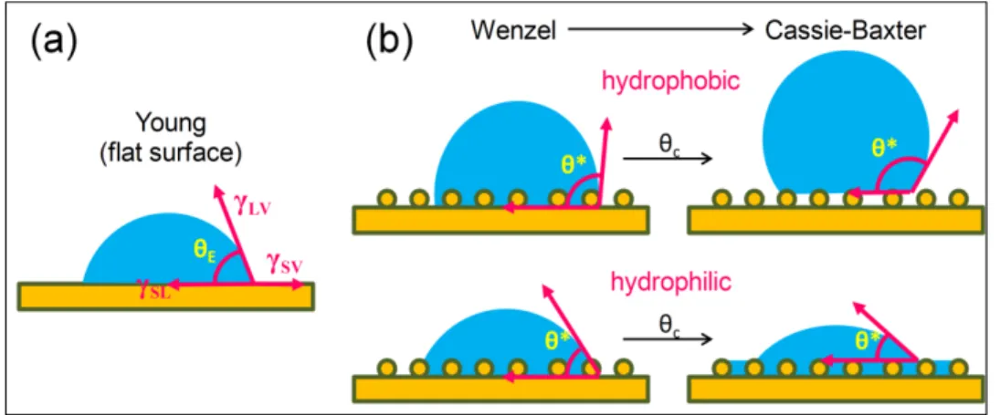
processing parameters that will influence the final wettability. ...13 Figure 1.3 – Basics of wetting: (a) A droplet deposited on a perfectly flat surface
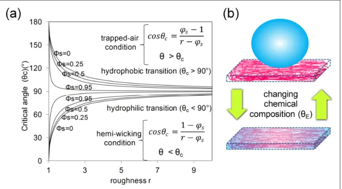
forming an equilibrium contact angle θE according with the energies involved; (b) Wetting on rough surfaces, characterized by the observed contact angle θ*, showing the transition from Wenzel to Cassie-Baxter state, defined by a critical contact angle θc. ...14 Figure 1.4 – Wetting in porous structures: (a) Critical contact angle as a function of
roughness and solid fraction; (b) typical switching mechanism in porous structures like electrospun mats, from hydrophobic (Cassie-Baxter state) to complete absorption of water by simple chemical modification. ...15 Figure 1.5 – Measuring the advancing and receding contact angle by (a) increasing
or decreasing the drop volume or (b) tilting the surface until the drop starts to slide or roll...17 Figure 1.6 – Evaluating the wettability of hydrophilic mats: (a) wicking
measurements on a mat strip to analyze the liquid rise dynamics;
(b) high-speed imaging to observe the dynamics of droplet impact. ...18 Figure 1.7 – Schematic showing the main approaches to modify ...19
Figure 1.8 – Schematic showing surface hydrophilization by plasma treatment
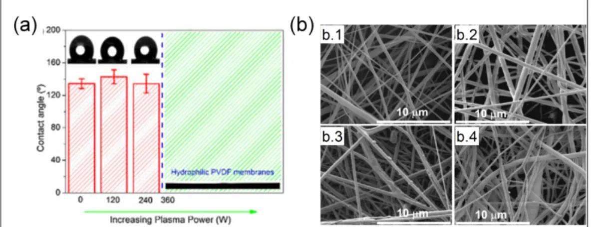
(Oh & Lee, 2013) ...21 Figure 1.9 – PVDF electrospun mats treated by plasma and the (a) influence of
plasma power on the contact angle; (b) mat morphology as a function of applied power: no treatment (b.1), 240 W (b.2), 360 W (b.3) and
480 W (b.4) (Correia et al., 2015). ...24 Figure 1.10 – Electrospun PCL mats treated by plasma with (a) and without (b) an
aluminum oxide template (c) (Jeon & Kim, 2014). ...26 Figure 1.11 – Effect of plasma treatment on the wettability of electrospun PCL mats:
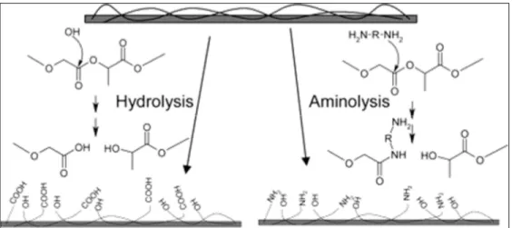
(a) untreated mat; (b) treated without the aluminum oxide template; (c) treated with template; (d) comparison of water absorption capacity (Jeon & Kim, 2014). ...26 Figure 1.12 – Hydrolysis and aminolysis reactions to introduce hydrophilic groups
on the surface of PLGA (Croll, O'Connor, Stevens, & Cooper-White, 2004). ...28 Figure 1.13 – Proposed wetting mechanism for (a, b) PVA-silanol fibers after
silanazation with strong adhesion due to the low receding contact angle; (c, d) PVA/silica-silanol fibers after silanazation showing air pockets that helps to increase the receding contact angle
(Pisuchpen et al., 2011). ...33 Figure 1.14 – The main approaches to graft polymers on a surface: (a) grafting-to, in
which the macromolecules are grafted to functional groups and (b) grafting-from, in which polymerization occurs directly on the surface (Araki, 2013). ...34 Figure 1.15 – PVDF electrospun mat: (a) untreated, (b) top surface after plasma
exposure, (c) top surface after MMA grafting and (d) bottom surface after MMA grafting (Kaur et al., 2007). ...38 Figure 1.16 – Atomic force microscopy images showing the grafted layers on
PMMA-co-BIEM fibers grafted with (a) PMAPS, (b) PHEMA and (c) PFA-C8-grafted (Yano et al., 2011). ...39 Figure 1.17 – Wettability of PS nanofibrous mats with solid fibers (PS-sNF) as a
function of coating time in PDOPA solution: (1) Contact angle evolution for (a) uncoated mats, (b) PS mats coated for 15 minutes (PS-sNF-15), (c) PS mats coated for 90 minutes; (2) Moisture transport behavior for the same compositions, showing the water content on the top surface of the mat where the liquid is sprayed and on the bottom surface to evaluate the transport ability (Dong et al., 2014). ...45
Figure 1.18 – SEM images and respective contact angle of PMMA/O-MMT composite fibers (a) untreated and sputter-coated with TiO2 with (b) 80 W, (c) 100 W, (d) 120 W and (e) 200 W of sputter power.
TEM image of (a) showing nanoclay domains (Q. Wang et al., 2011). ....47 Figure 1.19 – Dual-morphology with thicker and spiderweb-like thinner nanofibers
found in electrospun nanocomposites of (a) TPU/Tourmaline (95/05 wt%) (Tijing et al., 2012) (Reproduced with permission from Elsevier Ltd, UK) and (b) PA6/HAp (90/10 wt%)
(Abdal-hay, Pant, et al., 2013). ...52 Figure 1.20 – Wicking behavior of PAN/fumed silica composite mats as a function of
additive (A150 or R805) concentration: (a) water uptake as a function of time; (b) total absorbed water after wicking; (c) wicking height as a function of time (Dufficy et al., 2015). ...54 Figure 1.21 – Schematic of blending immiscible polymers by electrospinning and
some of the possible bulk and surface morphologies. ...56 Figure 1.22 – Contact angle results for PS/PVME fibers, miscible and immiscible, and
miscible films (Valiquette & Pellerin, 2011). ...60 Figure 1.23 – Effect of blending on the mat morphology: (a) Pure PET and (b)
PET/PVA (20/1 proportion) blend (G. Li et al., 2013) (Reproduced with permission from Elsevier Ltd, UK); (c) Pure PCL and (d) PCL/n-chitin (95:05) blend (Ji et al., 2014). ...62 Figure 1.24 – Amount of oxygen at the surface of SEBS/PEO-PPO-PEO electrospun
fibers prepares with different PEO-PPO-PEO (F127, P123, and L61). From bottom to top, the solid lines show the theoretical amount of oxygen according to the bulk compositon, pure L61, pure P123 and pure F127 (Rafael S. Kurusu & Demarquette, 2016). ...64 Figure 3.1 – Water contact angle for the electrospun mats (black diamonds) and
dip-coated films (open circles) as a function of F127 concentration in the SEBS/F127 blends. The insert shows the vials containing each solution. .76 Figure 3.2 – Water droplet fast spreading for the superhydrophilic SEBS/F127_20
electrospun mat. ...76 Figure 3.3 – Electrospun fibers observed by SEM with 100x magnification: (a) pure
Figure 3.4 – XPS results: (a) Measured % of oxygen atoms converted in wt% of F127 vs. bulk wt% of F127 for the electrospun mats (black diamonds) and dip-coated films (open circles); (b) High resolution XPS spectra for the electrospun SEBS/F127 mats with 5, 10, 15 and 20 wt% of F127. ...80 Figure 3.5 – Dip-coated films observed by transmitted light microscopy at 1000x
magnification: (a) Pure SEBS, and increasing F127 concentration to (b) 5 wt% (c) 10 wt% (d), 15 wt% (e) 20 wt% (f) and pure F127. Scale bars correspond to 20 μm. ...82 Figure 3.6 – Dip-coated films observed by SEM in secondary electrons mode and
1000x magnification for the (a) SEBS/F127_20 blend, and (b) pure F127. Scale bars correspond to 20 μm. ...83 Figure 3.7 – SEM images of (a) Pure SEBS, (b) SEBS/F127_15 and
(c) SEBS/F127_20 at 10.000x magnification. The scale bars
correspond to 1 μm. ...84 Figure 3.8 – AFM experimental scheme for electrospun fibers with a scan area of
500nmX500nm; (a-d) Phase images of (a) Pure SEBS, (b) region 1 of SEBS/F127_15, (c) region 2 of SEBS/F127_15, and
(d) SEBS/F127_20. ...85 Figure 3.9 – Schematic simplified illustrations of a water drop in contact with
electrospun mats for the hydrophobic and superhydrophilic
compositions. ...86 Figure 4.1 – Water contact angle results for all electrospun mats as a function of
PEO-PPO-PEO content. The insert is a plot of the hemi-wicking condition (J. Bico et al., 2001), the critical contact angle θc as a
function of roughness r for different values of solid/liquid interface
fraction (φS). ...94
Figure 4.2 – (a) spreading and imbibition experiments methodology and results for the contact angle θ as a function of time; (b) drop impact images showing the last frame before impact as the first image and the total time for absorption as the final image for F127_20, P123_20 and
L61_20 (top to bottom). ...97 Figure 4.3 – Results for the wicking measurements: (a) example of the experiments
pictures and the results for height as a function of time; (b) the square of height (h2) versus time; (c) Diffusion coefficient D and total time to
Figure 4.4 – (a) SEM micrographs of the samples containing 5 and 20 wt% of PEO-PPO-PEO (scale bar = 20 μm) and (b) the results of fiber diameter as a function of PEO-PPO-PEO content for all samples. ...102 Figure 4.5 – (a) X-ray photoelectron spectroscopy (XPS) survey spectra for pure
SEBS, F127_20, P123_20, L61_20 and pure PEO-PPO-PEO; (b) XPS results of the atomic percentage of oxygen as a function of blend bulk composition. The straight lines are theoretical values based on the
chemical structure of each molecule. ...103 Figure 4.6 – Wicking results as a function of the number of EO segments in each
side of the PEO-PPO-PEO molecules. ...104 Figure 4.7 – L61_20 fibers: (a) L61 leaching observed by optical microscopy, in
which the arrows indicate the water front advancing direction
(scale bar = 10 μm); (b) SEM image of the same composition showing broken fibers (scale bar = 30 μm). ...106 Figure 5.1 – Mat morphology and static contact angle results for (a) pure SEBS,
(b) F127_20, (c) P123_20 and (d) PEO_20. ...114 Figure 5.2 – XPS results: (a) Survey spectra for pure PEO-PPO-PEO and pure
SEBS showing the photoemission peaks of C 1s and O 1s. (a) Surface chemical composition of SEBS/PEO-PPO-PEO or SEBS/PEO blends after processing (day 1) as a function of PEO-PPO-PEO (F127 or P123) or PEO concentration (0, 5, 10, 15 and 20 wt%). ...115 Figure 5.3 – XPS aging results: (a) Survey results showing PEO or PEO-PPO-PEO
(F127 or P123) segregation to the surface over time in the SEBS blends; (b) High-resolution spectra showing intensity increase in the –C-O- peak over time...116 Figure 5.4 – Possible blend surface morphologies according to surface energy values
and spreading coefficients. Polymer 1 (orange) is the SEBS matrix and polymer 2 (green) represents either PEO or PEO-PPO-PEO. ...119 Figure 5.5 – Edge of a cut mat and cross section of a fiber after washing: (a) and
(b) PEO_20; (c) and (d) P123_20. Scale bars = 20 μm in (a) and
Figure 5.6 – Schematic illustrations: (a) solutions containing SEBS and
PEO-PPO-PEO with pictures of representative solutions; (b) surface enrichment and hydrophilization mechanism with amphiphilic PEO-PPO-PEO and pure PEO (out of scale); (c) Aging mechanism showing PEO-PPO-PEO molecules that continue to segregate to the surface over time after solidification. ...124 Figure 5.7 – Evolution in oxygen content over time for the blends containing 5 and 10
LIST OF ABREVIATIONS
AA Acrylic acid
AFM Atomic Force Microscopy
ATRP Atom transfer radical polymerization
BIEM 2-(2-bromoisobutyryloxy) ethyl methacrylate (BIEM)
CA Cellulose acetate CF4 Tetrafluoromethane CNC Cellulose nanocrystal CNT Carbon nanotubes CS Chondroitin sulfate DOPA Dopamine DTMS Decyltrimethoxysilane ECM Extra cellular matrix
F108 Pluronic F108 (PEO-PPO-PEO) F127 Pluronic F127 (PEO-PPO-PEO) FAS Fluoroalkylsilane
FPU Flourinated Polyurethane
GO Graphene oxide
HA Hyaluronic acid
HAp Hydroxyapatite
HCL Hydrochloric acid
iCVD Initiated chemical vapor deposition
L61 Pluronic L61 (PEO-PPO-PEO)
LCST Lower critical solution temperature
LiClO4 Lithium perchlorate
MAA Methyl methacrylate
MWCNT Multiwalled carbon nanotubes
NaIO4 Sodium periodate
NaOH Sodium hydroxide
NIPAAm N-isopropylacrylamide
O-MMT Organically modified montmorillonite (O-MMT) P123 Pluronic P123 (PEO-PPO-PEO)
PA6 Polyamide 6
PAA Poly(acrylic acid)
PAN Polyacrylonitrile PANi Polyaniline PBLG poly(γ -benzyl-L-glutamate) PCL Poly(ε-caprolactone) PDLLA Poly(DL-lactide) PDMS Poly(styrene-b-dimethylsiloxane) PDOPA Polydopamine
PEG Poly(ethylene glycol)
PEI Polyethyleneimine
PEO Poly(ethylene oxide)
PEO-PPO-PEO Poly(ethylene oxide)-b-poly(propylene oxide)-b-poly(ethylene oxide)
PET Polyethylene terephthalate
PFA-C8 Poly(2-(perfluorooctyl)ethyl acrylate) PFDTS Perfluorodecyltrichlorosilane
PGA Poly(glycolic acid)
PHA Polyhydroxyalkanoates
PHBV Poly(3-hydroxybutyrate-co-3-hydroxyvalerate)
PHEMA Poly(2-hydroxyethyl methacrylate)
PLA Polylactide
PLACL Poly(l-lactic acid)-co-poly(ε-caprolactone)
PLCL Poly (e-caprolactone-co-lactide)
PLLA Poly(l-lactic acid)
PMAPS Poly(3-(N-2-methacryloyloxyethyl-N,N-dimethyl) ammonatopropanesulfonate)
PMIA Poly(m-phenylene isophthalamide)
PMMA Poly(methyl methacrylate)
PNIPA Poly(N-isopropylacrylamide) PNIPAAm poly(N-isopropylacrylamide)
POSS Polyhedral Oligomeric Silsesquioxane
PP Polypropylene
PPFEMA Poly(perfluoroalkyl ethyl methacrylate)
PPO Poly(propylene oxide)
PS Polystyrene
PSMA Polystyrene/maleic anhydride
Psu Polysulfone
PTFE Polytetrafluoroethylene (Teflon)
PU Polyurethane
PVA Poly(vinyl alcohol)
PVB Polyvinyl butyral
PVDF Poly(vinylidene fluoride)
PVDFhfp Poly(vinylidene fluoride-co-hexafluoropropylene)
PVME Poly(vinyl methyl ether)
PVP Polyvinylpyrrolidone QCM Quartz crystal microbalance
RC Regenerated cellulose
SEBS Poly(styrene)-b-poly(ethylene-butylene)-b-poly(styrene) SEM Scanning Electron Microscopy
SiCl4 Silicon tetrachloride
TBAB Tetrabutylammonium TEOS Tetraethylorthosilicate
TiO2 Titanium dioxide
TPU Thermoplastic polyurethane
XPS X-ray photoelectron spectroscopy
ZnO Zinc Oxide
LIST OF SYMBOLS
D Diffusion coefficient
d Fiber diameter
f Distance between fibers (Chapter 4) or free volume fraction (Chapter 5) fg Free volume fraction at the glass transition temperature
h Height
r Roughness factor (Chapter 1) or radius (Chapter 4) t Time
T Temperature Tg Glass transition temperature
v Drop volume
We Weber number
α2 Difference between the thermal expansion coefficient above and below the glass transition temperature
γ Surface tension or surface energy (Chapter 5) γd Dispersion component of surface energy γp Polar component of surface energy
γSL Surface energy between the solid and the liquid γSV Energy between the solid and the air/vapour
η Liquid viscosity
θ* Observed contact angle
θADV Advancing contact angle
θc Critical contact angle
θE Equilibrium contact angle
θREC Receding contact angle
θtilt Tilt angle
ρ Density
INTRODUCTION
Electrospinning is a polymer processing technique that has gained much attention due to its ability to produce porous structures that have potential applications in a wide range of technologies, including filtration, separation, sensing, tissue engineering and drug delivery. The electrospinning process is based on the formation of micro or nanofibers from a polymer solution under an electric field. The solution is usually directed through a nozzle charged with a few kilovolts with controlled flow rate. If the solution properties such as viscosity, surface tension and conductivity, and the processing parameters such as voltage, flow rate and distance to a grounded collector are well adjusted, a thin jet erupts from the solution droplet at the tip of the nozzle. This charged jet travels towards the grounded collector and as it travels bending, due to electrostatic interactions, and solvent evaporation occur. Solid fibers are then deposited on the collector as a nonwoven mat of randomly aligned fibers. The electrospun mat has an interconnected porous structure with high surface area-to-volume ratio whose pore size can be tuned according to the fiber diameter. The control of surface properties is therefore particularly important for this type of structure. The interaction between the solid fibers with aqueous fluids, or wettability, is one of the surface properties that have a great impact in many applications. As an example, mats used in tissue engineering, also known as scaffolds, present better cell attachment and proliferation if the fibers are hydrophilic, i.e., have a greater tendency to be wet by water. Hydrophobic mats can be used as oil-water separation membranes to block the passage of water while letting oil pass.
In many cases, the appropriate polymer for electrospinning does not have the desired surface properties and thus surface modification is required. Many polymers used in biomedical applications, for example, are naturally hydrophobic and need to undergo a hydrophilization process to improve their performance. The electrospun mats can be treated by plasma or a
wet-chemistry method to create hydrophilic groups on the surface of the fibers, or they can be coated with a hydrophilic material, for instance. Sometimes, however, the post-treatment can deteriorate the fibers and consequently the mat structure or simply fail to reach deeper fiber layers inside the mat.
Surface modification can be also performed during electrospinning in a one-step process. The incorporation of a second polymer to the electrospinning solution, or blending, can significantly alter the surface properties of the resulting fibers provided that the modifying polymer is present on the surface after the process. The hydrophilization of electrospun mats by blending has been achieved in some studies found in literature, but there is still a lack of understanding about the basics of wetting of porous structures, the role of blend morphology and energy factors that contribute more to the surface segregation of the surface modifying polymer. Most of the work used hydrophilization only as a step before testing for a specific application. From a materials science perspective there are still a lot of unanswered questions.
0.1 Research Hypothesis
Within the context outlined above, the hypothesis is that surface modification of electrospun mats, in particular the hydrophilization of hydrophobic mats, can be achieved in a one-step process, that is, together with electrospinning by controlling the location of surface modifying agents and thus obtaining a homogeneous surface treatment.
0.2 Objectives
The main objective of this thesis is to develop a one-step method to achieve and control the hydrophilicity of hydrophobic electrospun mats that could be an alternative surface modification method and also circumvent some of the problems associated with post-treatments such as fiber degradation and lack of penetration. Many research topics such as the electrospinning process, multiphase systems and wetting of porous structures are
involved and many parameters such as the surface segregation, morphology and chemical composition have to be understood. The specific objectives of this thesis are thus defined as:
1. Evaluate polymer blending with an amphiphilic PEO-PPO-PEO copolymer as a method to achieve hydrophilization of SEBS, chosen as the hydrophobic matrix, by preparing and thoroughly characterizing the system SEBS/PEO-PPO-PEO (chemical composition, morphology, contact angle) produced by electrospinning and dip-coating;
2. Fabricate and characterize electrospun mats of SEBS/PEO-PPO-PEO blends with three types of commercially available PEO-PPO-PEO copolymers, with different molar masses and PPO/PEO ratio, and evaluate the possibility of tuning the surface properties in terms of segregation, wettability and robustness of the treatment;
3. Evaluate different characterization techniques to distinguish between different hydrophilic mats, given the limitation of a single contact angle measurement to evaluate the wettability of hydrophilic porous structures;
4. Understand the fundamental mechanisms involved in surface segregation during and after electrospinning by preparing blends of SEBS and PS with pure PEO, which has a relative high surface energy, and amphiphilic PEO-PPO-PEO, which has a low surface energy PPO block. Compare segregation of the same polymer inside different matrices.
CHAPTER 1
SURFACE MODIFICATION TO CONTROL THE WETTABILITY OF ELECTROSPUN MATS
The performance of electrospun mats in many applications is greatly affected by their interaction with water. Superhydrophobic mats can be used as separation membranes while superhydrophilic mats are usually preferred for tissue engineering. In many cases, however, the polymer used to produce the fibers does not have the appropriate surface properties, which need to be tuned. This review covers the main surface modification techniques used to change the wetting behavior of mats produced by electrospinning. Some basic aspects of the electrospinning process, as well of the wetting theories, are also presented as a starting point for the discussion, highlighting the common wetting switching mechanism found in highly porous structures like electrospun mats. The techniques are classified as post-treatments, or after-electrospinning, and one-step during electrospinning.
1.1 Introduction
The interconnected porous structures produced by electrospinning are increasingly interesting to a vast array of applications. These nonwoven mats are formed by polymer fibers with diameter generally ranging from hundreds of nanometers to a few micrometers. In the most common scenario the fibers are randomly deposited and the geometry of the mat depends on the average distance between fibers and fiber diameter, which influence the pore size (Lowery, Datta, & Rutledge, 2010). Mats can be composed of cylindrical fibers with uniform diameter or different morphologies like ribbon-shaped or beads-on-string fibers. Considering the generally high surface area-to-volume ratio of these mats, the control of surface properties is crucial and can be achieved by controlling the geometry of the mat and the surface chemical composition and morphology of the fibers. The wettability is one of the
most important surface properties that needs to be understood and controlled, in light of the many possible applications in which the fibers interact with water or an aqueous medium.
In general terms, wettability determines if a material has more or less affinity with water and so a polymer can be either naturally hydrophilic or hydrophobic. In the case of perfectly flat films, this property is defined only by the chemical composition of the outermost molecular layers and the characterization of wettability is usually done by the measurement of water contact angle on the surface. However, electrospun mats are composed of fibers and interconnected air pores and can be seen as a rough surface in the hydrophobic case and as porous structure in the hydrophilic case. According to wetting theories (José Bico, Thiele, & Quéré, 2002; Callies & Quere, 2005; Shirtcliffe, McHale, Newton, Perry, & Roach, 2005), these characteristics favor more extreme cases of high static contact angle values for mats made of hydrophobic polymers and near-zero contact angle values for water-absorbing mats made of hydrophilic polymers (C. H. Kim, Khil, Kim, Lee, & Jahng, 2006; G. Li, Zhao, Lv, Shi, & Cao, 2013; Valiquette & Pellerin, 2011).
However, many times the appropriate polymer for processing or with the desired bulk properties does not present the ideal wetting behavior so that surface modification for hydrophobization/hydrophilization is needed. Also, surface modification enables the tuning of both bulk and surface properties of the materials, making them more functional. Changing the surface properties of electrospun mats can be done after processing by different techniques such as plasma treatment, wet-chemistry methods, coating, etc, adding at least one more step after electrospinning to achieve the desired properties. But surface modification can also be done during electrospinning by incorporating nanoparticles or blending with surface modifying polymers that segregate to the surface, for example.
The present work is a review of the main surface modification techniques used for electrospun mats aiming to change their wettability. The principles of the main techniques are presented and discussed with examples, highlighting the advantages and drawbacks of each technique. This review is intended to be an introduction for researchers and engineers
working with electrospinning and looking for options to tune the wettability of mats for a given application.
1.1.1 Applications of mats with controlled wetting behavior
There are several applications in which it is necessary to control the affinity of electrospun membranes with water. Figure 1.1 shows some examples that are briefly discussed below.
Figure 1.1 – Possible applications of electrospun mats with controlled wettability (a) PAN electrospun membrane used for oil-water separation after surface modification (X. Li, Wang, Wang, Cheng, & Wang, 2014); (b) Schematic apparatus of a humidity sensing system where electrospun fibers are deposited on the electrode inside the humidity chamber (Xianfeng, Bin,
Jianyong, Moran, & Fukui, 2010); (c) water droplets deposited on superhydrophobic electrospun PS-PDMS/PS blends (Minglin Ma, Hill, Lowery, Fridrikh, & Rutledge, 2005); (d) Fluorescence micrograph showing myoblast cells in a PLGA/gelatin/α-elastin electrospun
mat used for tissue engineering (M. Li et al., 2006); (e) Three different strategies to load drugs on the surface of electrospun fibers (Yoo, Kim, & Park, 2009).
1.1.1.1 Membranes for separation/filtration
Perhaps the clearest example of application in which wettability is important is the use of porous membranes to separate immiscible liquids such water and oils or other type of contaminants related to environmental problems (Darmanin & Guittard, 2014; Xue, Cao, Liu, Feng, & Jiang, 2014). Oils have lower values of surface tension (ranging around 20 to 40 mN/m) (Grynyov et al., 2016) when compared to water (surface tension of 72 mN/m) so that it is easier to wet a surface with oil and thus the most common approach for water/oil separation is the use hydrophobic or superhydrophobic and superoleophilic membranes that let oil pass through but block the passage of water (Figure 1.1a) (Darmanin & Guittard, 2014; Xue et al., 2014). PS is the most commonly investigated polymer to produce electrospun membranes for oil-water separation. It can be easily dissolved in different solvents and the microstructure of the fibers can be tuned by altering different material properties and processing parameters such as molecular weight, solvent type, concentration and relative humidity (M. W. Lee et al., 2013; J. Lin, Ding, Yang, Yu, & Sun, 2012; J. Lin, Y. Shang, et al., 2012; Pai, Boyce, & Rutledge, 2009; Wu et al., 2012). As an example, hydrophobic PS electrospun mats with highly porous fibers showed a drastic increase in oil absorption capacity when compared to commercial nonwoven PP mats with thicker and non-porous fibers (J. Lin, B. Ding, et al., 2012; J. Lin, Y. Shang, et al., 2012; Wu et al., 2012). In other cases, surface modification such as the incorporation of nanoparticles is needed to improve the hydrophobicity and consequently the separation efficiency of the electrospun polymer (Tai, Gao, Tan, Sun, & Leckie, 2014; Tuteja et al., 2007).
Wettability is also critical in water filtration technology, in which hydrophilic electrospun mats can be used to control the passage of water while blocking particles. Moreover, the pore size of electrospun mats can be tuned to be smaller than in commercial fibrous filtration membranes, which drastically increases filtration efficiency while the interconnected structure maintains the appropriate permeability (B. Sun et al., 2014). Mats of PVDF or PSu, for instance, are interesting for water treatment due to their good mechanical properties and chemical resistance, but their hydrophobicity decreases the flow of water through the
membrane. The incorporation of surface-modification molecules makes the mat more hydrophilic and enables higher water-flux rates at lower pressures (Kaur, Rana, Matsuura, Sundarrajan, & Ramakrishna, 2012).
1.1.1.2 Sensing applications
Sensing applications can also benefit from the large specific area of electrospun mats, presenting higher sensitivity than flat films. Hydrophilic fibers, for example, can be deposited on a QCM electrode to act as humidity sensors, as shown in the apparatus illustrated in Figure 1.1b. The principle is based on the adsorption of water molecules on the surface of the fibers deposited on the QCM electrode that will induce a response variation of the quartz crystal and lead to a change in the resonance frequency and therefore on the measured mass (Marx, 2003; X. Wang, Ding, Yu, & Wang, 2011; Xianfeng et al., 2010). In addition to the large surface area, the ideal material must be sensitive to humidity and electrical signals. Examples include electrospun PA6 mats deposited on QCM electrodes and impregnated with sensing PEI, which outperformed flat films with higher sensitivity and faster response time in the detection range of 2-95% of relative humidity (X. Wang et al., 2011), and PEO mats doped with LiClO4 that also outperformed flat films, but in this case the fibers were damaged after the measurement, making it a disposable humidity sensor (Aussawasathien, Dong, & Dai, 2005).
1.1.1.3 Self-cleaning surfaces and antifouling membranes
Superhydrophobic electrospun mats (Figure 1.1c) can also be employed as a self-cleaning surface, not only repelling water but also using rolling water droplets to clean the surface from dust particle, for example (Sas, Gorga, Joines, & Thoney, 2012). The lotus leaf found in nature exhibits this behavior and a lot of effort has been put to mimic its microstructure composed of micro and nanoroughness that makes the water droplets bounce and roll (Jiang,
Zhao, & Zhai, 2004). Mats with beads-on-string morphology produced by electrospinning can show similar properties but water repellency is more stable by combining these geometric features with low surface energy materials on the surface (Tuteja et al., 2007). In the opposite case, hydrophilization also reduces the accumulation of proteins, bacteria and other organisms, known as fouling (Banerjee, Pangule, & Kane, 2011; Huang et al., 2014). One of the most common approaches to avoid fouling is the use of hydrophilic surfaces containing PEO/PEG due to the high hydrophilicity, flexibility, and mobility of its chains (Y.-q. Wang et al., 2005). Many surface modifications methods can be use to impart PEO on the surface of electrospun mats, from grafting to blending, and they are mainly concentrated on biomedical applications.
1.1.1.4 Tissue engineering and drug delivery
The resemblance of electrospun mats with the natural ECM makes them a natural fit as a substrate for tissue engineering (Agarwal, Wendorff, & Greiner, 2008; Zeng et al., 2003). The natural ECM is composed, among many other components, of hydrophilic carbohydrate polymers. Hydrophilicity increases cell affinity so that hydrophobic polymers used in tissue engineering such as PLA, PHAs or PCL need to undergo surface modification (Liang, Hsiao, & Chu, 2007). By incorporating minerals in PCL (Araujo et al., 2008) or PHBV (Ito et al., 2005) mats to mimic the ECM found in bone structures, for instance, the resulting hydrophilic mats presented increased cell attachment and proliferation. Figure 1.1d shows an example of cells in a PLGA scaffolds blended with gelatin and elastin, a natural protein(M. Li et al., 2006). Another promising biomedical application where the wettability is important is drug delivery. Drugs can be incorporated on the surface of electrospun fibers in different ways (Figure 1.1e), or they can be embedded in the matrix with different morphologies (Sill & von Recum, 2008). The wetting behavior of the polymer matrix must be tailored to enable a better drug encapsulation (Zeng et al., 2003). Amphiphilic block-copolymers, for example, can form micelles used to encapsulate hydrophobic drugs and at the same time increase the dispersions inside a hydrophilic matrix (Rösler, Vandermeulen, & Klok, 2012), or they can be used to tune drug release rate (K. Kim et al., 2004).
1.2 Basic principles
1.2.1 Electrospinning process
Electrospinning is a technique in which polymer fibers are formed, generally from a solution, under an electrical field. In the most basic apparatus, the solution is placed inside a syringe and directed through a charged syringe needle. Raised to a high potential, the drop formed at the needle tip is elongated until a thin jet erupts and travels towards a grounded collector. The jet experiences bending instabilities and solvent evaporation before the solid fibers reach the collector deposited as a nonwoven mat (Reneker & Yarin, 2008; Rutledge & Fridrikh, 2007). The charged drop deformation phenomenon and jet eruption was described by Zeleny (1917) (Zeleny, 1917). Later, the theory was further developed by Taylor (1964), who described the conditions for the droplet instability in high fields that leads to the formation of a conic shape before the eruption. Taylor hypothesized that the electric field is locally greater at the vertex of the cone, as an explanation for this region to be the first to accelerate, and for the fact that is possible to generate fibers thinner than the capillary from which the solution ejects (Taylor, 1964). However, it was not until the mid-nineties that this technology experienced a resurgence, with the work of Doshi and Reneker (1996) as an example that showed the formation of polymer fibers from different solution, with different diameters and cross-sections, which had the potential for many applications(Doshi, 1995). After that, the number of publications on electrospinning increased dramatically. Although the phenomena involved is a complex interplay of solution characteristics such as rheological properties, surface tension, conductivity and evaporation rate, with the processing parameters like applied voltage, flow rate, distance to the collector, temperature and humidity, the basic apparatus is easy to assemble in a laboratory and the technique has proven to be remarkably versatile.
A non-woven mat composed of randomly aligned fibers is the most common type of structure obtained by electrospinning. Alternatively, rotating or air-gap collectors can produce aligned fibers and a processing variation called near-field electrospinning with a collector with controlled movement enables the design of mats with more precise geometry (D. Li, Wang, & Xia, 2003; Persano et al., 2013; D. Sun, Chang, Li, & Lin, 2006). Nevertheless, for this review’s purpose, we consider an electrospun mat as an interconnected porous membrane in which the pores are formed by fibers randomly deposited. Mat morphology (mat geometry) is defined by fiber diameter/shape and fiber deposition. Many factors influence the final fiber diameter including the polymer choice, solvent type, evaporation rate, dielectric constant, solution viscosity and surface tension, electric field intensity, and others (Figure 1.2). The final fiber diameter, therefore, can be tuned and range from a hundred nanometers to a few micrometers. All these parameters also influence the shape of the fibers, which can be uniform with circular cross-section, ribbon-shaped fibers, wrinkled fibers, etc. The competition between “fluid forces” such as viscosity and surface tension and electric forces defines if particles (electrospraying) or fibers (electrospinning) will be obtained, with the beads-on-string morphology in-between these two limits (Deitzel, Kleinmeyer, Harris, & Beck Tan, 2001; Reneker & Yarin, 2008; Rutledge & Fridrikh, 2007). Fiber surface morphology is also highly influenced by materials and processing parameters. The choice of polymer, solvent system and relative humidity can create either smooth or porous fibers (Pai et al., 2009). Different blend morphologies (Rafael S. Kurusu & Demarquette, 2015), interactions between solvents and non-solvents (Pai et al., 2009), incorporation of nanoparticles (M. Ma et al., 2007), are some of the possibilities to alter the fiber surface roughness and chemical composition, the two factors that will influence its wetting behavior.
Figure 1.2 – Schematic of the electrospinning process with the main material and processing parameters that will influence the final wettability.
1.2.2 Wettability of electrospun mats
When a droplet of water is placed on a flat surface a contact angle θE is formed, representing the equilibrium of all the interfacial energies involved and indicating the affinity of the surface with water (Figure 1.3a). If θE is lower than 90° the surface is hydrophilic; if greater than 90°, hydrophobic. The introduction of roughness tends to amplify the original characteristic of the surface and so rough surfaces of hydrophobic materials have higher values of static contact angle when compared to the flat film. By increasing the roughness, the static contact angle increases as the droplet fills the whole surface area (Wenzel state, Figure 1.3b) up to a critical value in which the energy associated with the formation of air pockets under the droplet (Figure 1.3b) becomes lower than the energy related to following the whole solid surface(Callies & Quere, 2005). Air is trapped underneath and the droplet is deposited on a composite surface of air and solid (Cassie and Baxter state, Figure 1.3b) with even higher values of contact angle. In the hydrophilic case, the contact angle decreases while the droplet fills the roughness and the critical value marks the start of water impregnation by capillary action. The surface becomes wet ahead of the contact line and the
droplet is deposited on a composite surface of liquid and solid (J. Bico, Tordeux, & Quéré, 2001).
Figure 1.3 – Basics of wetting: (a) A droplet deposited on a perfectly flat surface forming an equilibrium contact angle θE according with the energies involved; (b) Wetting on rough surfaces, characterized by the observed contact angle θ*, showing the transition from Wenzel to
Cassie-Baxter state, defined by a critical contact angle θc.
Fundamental studies on wetting are commonly performed with surfaces of well defined geometry. Parameters like roughness (r), the ratio of the real surface area to the projected flat surface, and surface solid fraction φS are known and can be finely tuned, which makes the wetting transitions easier to observe. Porous structures like electrospun mats tend to have high values of roughness (r∞) and low values of surface solid fraction. The consequence is
that hydrophobic materials (equilibrium contact angle > 90°) produce electrospun mats with much higher static contact angle values (Cassie and Baxter state) while hydrophilic materials (equilibrium contact angle <90°) produce mats that absorb water by capillary action, or wicking, resulting in a final contact angle of practically zero, although the advancing front never reaches zero on partially wettable materials(José Bico et al., 2002). For the purpose of this review, contact angle of zero means that the surface completely absorbed the water droplet during contact angle measurements. Hemi-wicking is the appropriate term to describe the phenomenon because as the liquid fills the roughness, it leaves behind dry islands and thus is not a perfect wicking. The condition for hemi-wicking (José Bico et al., 2002; J. Bico et al., 2001) as a function of roughness and solid fraction is presented in Figure 1.4a and
considering the usual high roughness of electrospun mats, the critical contact angle that defines the onset of imbibition is always practically 90°, regardless of the solid fraction φs, as shown in Figure 1.4. This explains the switching mechanism (Figure 1.4b) often observed during static contact angle measurements of electrospun mats with different compositions. From hydrophobic with high static contact angle values to superhydrophilic absorbing structures (Rafael S. Kurusu & Demarquette, 2015; Shirtcliffe et al., 2005).
Figure 1.4 – Wetting in porous structures: (a) Critical contact angle as a function of roughness and solid fraction; (b) typical switching mechanism in porous structures like electrospun mats, from hydrophobic (Cassie-Baxter state) to complete absorption of water by
simple chemical modification.
Hydrophobic electrospun mats can be seen as a surface with high roughness and the fiber and pore diameter will define an average solid fraction, knowing that randomly aligned mats with thinner fibers have smaller pores (Lowery et al., 2010). Fiber surface chemical composition will define the wettability of the solid part so that polymers with lower surface energy
generate more hydrophobic mats (M. Ma, R. M. Hill, et al., 2005). One of the criteria for superhydrophobicity, observed contact angle higher than 150°, can be achieved even with weakly hydrophilic materials (equilibrium water contact angle on a flat film smaller than but close to 90°) depending on the surface re-entrant geometry (Herminghaus, 2000; Kota, Li, Mabry, & Tuteja, 2012), but this is a metastable state and the more robust superhydrophobic surfaces are produced by a combination of geometry, such as mats containing “beads on a string” morphology, and chemistry by using low surface energy materials (Tuteja et al., 2007). Still, high values of static contact angle do not make a surface water-repellent.
To truly characterize superhydrophobicity, the difference between the advancing and the receding contact angle, called contact angle hysteresis, has to be smaller than 10°. The experiment is usually done in two ways (Figure 1.5). In the first (Figure 1.5a), the advancing contact angle is measured using a droplet of water deposited on the surface that is continually filled until the contact line between surface, water and air moves outward. To access the receding angle, the opposite is done by extracting liquid from the droplet until the contact line moves inward. The second alternative (Figure 1.5b) is to tilt the surface until the droplet slides and measure both advancing and receding angles. A rough surface with high values of static contact angle and contact angle hysteresis will present a round water drop attached on the surface even if the mat is turned upside down, in a phenomenon described as petal effect (Feng et al., 2008). This type of surface avoids the water penetration but does not repel water. True water repellent surfaces will present low contact angle hysteresis, regardless of the static contact angle. Water will bounce or slide on those surfaces. The majority of studies presented in this review, however, do not take into account the contact angle hysteresis, relying only on static contact angle measurements to verify if the electrospun mats will be penetrated by an aqueous fluid.
Figure 1.5 – Measuring the advancing and receding contact angle by (a) increasing or decreasing the drop volume or (b) tilting the surface until the drop starts to slide or roll.
In hydrophilic mats, capillary action will lead to a static contact angle of practically zero so that this measurement is not enough to fully characterize the mat or to access the difference between different hydrophilic materials, helping only to attest if an aqueous fluid will penetrate the mat. Wicking experiments can be performed to further describe the dynamics of wetting in these mats (Figure 1.6a). Different hydrophilic materials can exhibit great difference in absorption rate or capacity, which will certainly affect the performance for some applications (Rafael S. Kurusu & Demarquette, 2016). Another alternative to compare different hydrophilic materials is the observation, which sometimes requires the use of high-speed imaging, of the dynamics of droplet spreading or impact on the surfaces (Figure 1.6b) (Rafael S. Kurusu & Demarquette, 2016; Z. Wang, Espín, Bates, Kumar, & Macosko, 2016). Differences in water absorption time indicate nonuniform surface properties (Cécile & Hsieh, 2010). As in the hydrophobic case, most studies presented in this review use mainly the static contact angle measurements to evaluate if the electrospun mat is hydrophilic. Studies in filtration science seem to pay more attention to the absorption time during contact angle measurements.
Figure 1.6 – Evaluating the wettability of hydrophilic mats: (a) wicking measurements on a mat strip to analyze the liquid rise dynamics; (b) high-speed imaging to observe the
dynamics of droplet impact.
1.3 Surface modification methods
In the recent literature, surface modification is used to achieve the adequate performance for a given application and therefore most articles are not only focused on changing the wettability or understanding the mechanisms behind the wetting behavior. Still, in all the studies cited below the effects of surface modification methods on the wettability of electrospun mats were at least briefly investigated.
Considering that biomedical applications represent the greatest research interest in electrospun scaffolds, one of the major goals of surface modification is to hydrophilize the surfaces. Hydrophilic surfaces are known to have better biocompatibility and the ability to avoid biofouling. A surface treatment such as plasma, hydrolysis or aminolysis can produce polar groups such as carboxyl, hydroxyl and amines on the surface to improve the hydrophilicity. Another approach is to incorporate hydrophilic polymers or nanoparticles to the fibers. In contrast, surface hydrophobization has also been investigated to create superhydrophobic surfaces or membranes, for example, and it can be achieved by the introduction of low surface energy groups on the surface like fluorine-containing groups, or mixing with hydrophobic polymers or nanoparticles. Surface modification can be chemical such as the introduction of functional groups by plasma treatment or wet-chemistry reactions, or yet grafted polymers covalently bonded to the surface. Physical modification methods
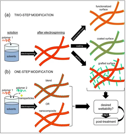
include coating, adsorption or blending. Figure 1.7 shows the main routes to change the wettability of electrospun mats based on recent literature. The methods are divided in two main groups in the following sections: (i) post-treatments performed after electrospinning (plasma, wet-chemistry, grafting and coating); (ii) one-step treatments performed during electrospinning (nanocomposites and blends). This division was meant to emphasize a big difference between these two approaches: for the methods performed after electrospinning the penetration of the treatment will be an important factor while for the methods performed during electrospinning the modification is ideally achieved in every mat layer.
Figure 1.7 – Schematic showing the main approaches to modify the surface of electrospun mats.
1.3.1 Post-treatments
1.3.1.1 Plasma
Plasma is a partially ionized gas formed by the same number density of negative and positive charge carriers (Strobel, Lyons, & Mittal, 1994), which can be created by heating the gas to extremely high temperatures or subjecting it to strong electromagnetic fields. Plasmas present collective behavior and are electrically conductive, responding to the presence of electromagnetic fields. Plasma processes were originally used to either etch a surface (removing material) or for the deposition of thin films. Surface treatment using plasmas can also modify only a few molecular layers with no significant amount of deposition or etching (Strobel et al., 1994).
Plasmas can be divided in thermal/high-temperature/hot plasma and non-thermal/low temperature/cold plasma. The former is characterized by very high temperatures and therefore is not suitable for temperature-sensitive materials like polymers (Morent, De Geyter, Desmet, Dubruel, & Leys, 2011). The advent of nonthermal/low-temperature/cold plasma processes, in which the gas molecules and ions are closer to the room temperature allowed the use of plasma treatments for polymers, reducing the risk of thermal degradation. Glow discharge is a source of nonthermal plasma formed by the passage of an electric current between two electrodes through a low-pressure gas. This type of plasma was originally used for etching and creating patterns on surfaces or to deposit thin films, usually operated in direct-current powering mode, which requires an electrically conductive sample to act as the negatively charged electrode (cathode). Alternatively, glow discharges can also be operated in radio-frequency mode, and in this case the treatment can be used for non-conductive materials like polymers thus broadening the possible applications of the technique. A thorough review on this type of plasma can be found in literature (Winchester & Payling, 2004). Corona discharge is another source of nonthermal plasma used for polymers, formed by the ionization of a fluid surrounding an electrically charged conductor under a strongly nonuniform electric field at atmospheric pressure (Desmet et al., 2009; Strobel et al.,
1994). The nonuniform electric field appears when one of the electrodes is much smaller than the distance between electrodes. A sharp electrode around which a glow is formed is normally used to treat the mats. Treatment by plasma can be used directly to create functional groups at the surface of the substrates, to etch, to cross-link, or to simply prepare the surface for another treatment such as coating or grafting. Plasma can also be used indirectly to graft polymers but this process will be discussed in more detail in the grafting section of this review. The introduction of hydrophilic polar groups like hydroxyl, carboxyl, amino, carbonyl, on the surface is the most common objective of plasma surface modification. The presence of these groups on the surface of hydrophobic polymer fibers will help to make the mats more hydrophilic and therefore more biocompatible for several biomedical applications. Figure 1.8 shows the simple generation of functional groups or radicals that can react with air or pure O2 and produce hydrophilic groups. Table 1.1 summarizes recent studies that used plasma treatment to change the wettability of electrospun mats.
Figure 1.8 – Schematic showing surface hydrophilization by plasma treatment (Oh & Lee, 2013).
Table 1.1 – Plasma treatment used to alter the wettability of electrospun mats
Polymer Treatment/Modification Wettability characterization Application ref
PA 6 Cold gas plasma treatment (O2) / Hydroxyl and carboxyl groups on the
surface
Environmental scanning electron microscopy: increased hydrophilicity on individual fibers
Surface modification
(Wei, Gao, Hou, & Wang, 2005) PCL Remote plasma treatment with
radio-frequency glow discharge (Ar)
Contact angle: untreated (82±4.1°) and treated (wicking) Tissue engineering
(Y. Duan et al., 2007) PLLA Plasma treatment (air) Contact angle: untreated (63±10.5°) and treated (32±5.5°)
(Aligned fibers)
Tissue engineering
(Corey et al., 2008) PCL Radio-frequency glow discharge plasma
treatment (Ar)
Contact angle: untreated (113±5°) and treated (wicking) Tissue engineering
(Yang, Wolke, & Jansen, 2008) PLACL and
PLACL/gelatin
Radio-frequency glow discharge plasma (air)/ Polar groups introduced
Contact angle: untreated PLACL (121°) and treated PLACL (wicking), untreated PLACL/gelatin (129°) and
treated PLACL/gelatin (wicking)
Tissue engineering (Chandrasekaran, Venugopal, Sundarrajan, & Ramakrishna, 2011)
CA and RC Low-pressure plasma with
trifluoromethane
Contact angle: untreated CA and RC (<25° to wicking) and treated CA (153.8±2.5°) and RC (154.8±0.7°)
Superhydrophobic textile
(Thorvaldsson et al., 2012) PLACL Radio-frequency glow discharge plasma
treatment (air)
Contact angle: untreated PLACL (129.3±2.8°) and treated (52.6±9.6°)
Tissue engineering
(Bishi et al., 2013) PLLA Non-thermal atmospheric pressure corona
discharge plasma (N2) / Carboxyl groups
Contact angle: untreated PLLA (121.5±1.7°) and treated PLLA (wicking) / Droplet absorption time around 70 seconds / Water uptake capacity: untreated (10%), treated
(> 300%)
Tissue engineering
Table 1.1 (continuation) - Plasma treatment used to alter the wettability of electrospun mats
Polymer Treatment/Modification Wettability characterization Application ref
PCL Radio-frequency glow discharge with selective exposure (O2)
Contact angle: instantly after deposition, untreated PCL (117±4°), treated without template (110±2.5°) and treated
with template (114.5±2.5°); after 300 seconds, untreated PCL (102±2°), treated without template (8±1°) and treated with template (23±3°) / Water uptake capacity:
untreated PCL (≈50%), treated without template (> 500%) and treated with template (> 400%)
Tissue engineering
(Jeon & Kim, 2014)
PVDF Radio-frequency glow-discharge plasma
(O2) / Carboxyl groups
Contact angle: untreated PVDF (134±6°) and treated PVDF (wicking, with a minimum power and treatment
time)
Surface modification
(Correia et al., 2015)
PET Atmospheric pressure corona discharge (air), low-pressure radio-frequency plasma
(Ar/O2 or O2), microwave plasma ashing (O2 or O2/CF4) / Polar groups (hydroxyl,
carbonyl, carboxyl)
Contact angle: untreated PET (137±3°) and treated PET (wicking) / Wicking time (2 cm height): untreated PET (no wicking), treated with low-pressure plasma with Ar/O2 or O2 (4.5 and 5s), treated with corona discharge (8.5s), treated with microwave plasma ashing with O2 or
O2/CF4 (8.5 and 9s)
Tissue engineering
(Savoji, Lerouge, Ajji, & Wertheimer,
2015)
PLLA Microwave plasma treatment (CF4) Contact angle: untreated PLLA (116±3°) and treated PLLA at 100W/5 min (32±3.6°), 100W/min (wicking), 150W/5 min (wicking), 150W/10 min (≈60°), 200 W or
more (> 120°)
Surface modification
(Yue et al., 2015)
PS Plasma treatment (air) / Hydroxyl groups introduced
Contact angle: untreated PS (139±2.7° to 161±2.6°, according to fiber morphology) and treated (wicking)
Surface modification
(Yuan, Choi, & Kim, 2016)
Nonthermal radio frequency glow discharge plasma is the widely used method for introduction of hydrophilic functional groups. Many hydrophobic electrospun mats of biodegradable polymer such as PCL (Yang et al., 2008), PLLA (Dolci et al., 2014) and PLACL (Chandrasekaran et al., 2011) were hydrophilized after the introduction of polar groups by the treatment, as revealed by contact angle experiments. PVDF is another hydrophobic polymer that in many cases needs to undergo surface modification to broaden its many possible applications in different fields including tissue engineering, filtration and sensing. In a recent study, deflourination and oxidation were promoted by radio frequency glow discharge plasma and all the treated PVDF mats presented increased C-O bond content at the surface. It was also observed that there was a minimal treatment time, around 60 seconds, above which the mats attained superhydrophilicity. Analogous behavior was observed with the plasma power used, with a minimum of 360 W to hydrophilize the mats (Figure 1.9a). The increased applied power also caused some etching that led to melting and merging of fibers in the outer layer (Figure 1.9b) (Correia et al., 2015).
Figure 1.9 – PVDF electrospun mats treated by plasma and the (a) influence of plasma power on the contact angle; (b) mat morphology as a function of applied power: no treatment (b.1), 240 W (b.2), 360 W (b.3) and 480 W (b.4) (Correia et