HAL Id: hal-00839978
https://hal.inria.fr/hal-00839978
Submitted on 1 Jul 2013
HAL is a multi-disciplinary open access
archive for the deposit and dissemination of
sci-entific research documents, whether they are
pub-lished or not. The documents may come from
teaching and research institutions in France or
abroad, or from public or private research centers.
L’archive ouverte pluridisciplinaire HAL, est
destinée au dépôt et à la diffusion de documents
scientifiques de niveau recherche, publiés ou non,
émanant des établissements d’enseignement et de
recherche français ou étrangers, des laboratoires
publics ou privés.
Lazy Parallel Synchronous Composition of In finite
Transition Systems
Yuliia Romenska, Frédéric Mallet
To cite this version:
Yuliia Romenska, Frédéric Mallet. Lazy Parallel Synchronous Composition of In finite Transition
Systems. International Conference on ICT in Education, Research and Industrial Applications, Jun
2013, Kherson, Ukraine. pp.130-145. �hal-00839978�
Lazy Parallel Synchronous Composition of
Infinite Transition Systems
Yuliia Romenska, Fr´ed´eric Mallet
Universit´e Nice Sophia-Antipolis
Aoste Team Project (INRIA/I3S), Sophia Antipolis [email protected], [email protected]
Abstract. Embedded System Design is becoming a field of choice for Model-Driven Engineering techniques. On the engineering side, models bring an abstraction of the code that can then be generated (and regen-erated) at will. On the semantic side, they bring a reasoning framework to guarantee or verify properties on the generated code. We focus here on the Clock Constraint Specification Language, initially defined as a companion language of the uml Profile for marte. More specifically, we define a state-based representation of ccsl operators. To deal with unbounded operators, we propose to use lazy evaluation to represent in-tentionally infinite transition systems. We provide an algorithm to make the synchronized product of such transition systems and we study its complexity. Even though the transition systems are infinite, the result of the composition may become finite, in which case the (semi)algorithm terminates and exhaustive analysis becomes possible.
Keywords. Multiform logical time, synchronized product, lazy evalua-tion, marte ccsl.
Key terms. FormalMethod, VerificationProcess, MathematicalModel, SpecificationProcess.
1
Introduction. Context and Goal of the Project
In the model-driven approach to embedded system engineering, application and architecture models are developed and refined concurrently, and then associated by allocation relationships. The representation of requirements and constraints in this context becomes itself an important issue, as they guide the search for optimal solutions inside the range of possible allocations. One of the important aspects of embedded system modeling is to capture the functional and non-functional requirements as well as the constraints (non-functional and non-non-functional) imposed by the execution platform through the allocation.
Multiform logical time is a flexible notion of time suitable for both functional and extra-functional properties that supports an iterative refinement process. Logical time considers time bases that can be generated from sequences of events not necessarily regular in physical time (as the usual meaning suggest). Some
of the essence of multiform logical time was captured and encapsulated into a dedicated language called the Clock Constraint Specification Language (ccsl) [1, 2]. ccsl was initially defined as a companion language of the uml profile for Modeling and Analysis of Real-Time and Embedded systems (marte) [3].
ccsl has arisen from different models in an attempt to abstract away the data and the algorithm and to focus on events and control. Even though ccsl was initially defined as the time model of the uml profile for marte, it has now become a full fledged domain-specific modeling language for capturing chrono-logical, causal and timed relationships and is now developed independently. It combines constructs from the general net theory and from the synchronous lan-guages [4]. It is based on the notion of clocks which is a general name to denote a totally ordered sequence of event occurrences. It defines a set of clock relations and expressions. Some ccsl operators are bounded, others are unbounded. The bounded operators can be represented with finite Boolean transition systems. Unbounded operators require a specific symbolic representation.
Until then, the clock calculus on ccsl specification was performed step by step up to a predefined number of steps. This work is an attempt to support exhaustive analysis of ccsl specification. When ccsl operators are represented as transition systems, their composition is the synchronized product of the tran-sition systems. However, this causes termination problems when the trantran-sition systems have an infinite number of states. In this paper, an algorithm for the parallel execution of automata representing ccsl operators is proposed. It has been implemented in a prototype tool. This algorithm supports ccsl unbounded operators. The infinite data structure is unfolded on demand using a lazy evalua-tion technique. This is a significant evoluevalua-tion on previous verificaevalua-tion techniques for ccsl [5,6] that were only considering a subset of operators a priori bounded.
2
Contribution
The main contribution is to propose an encoding based on lazy evaluation to rep-resent ccsl unbounded operators. The second contribution is to propose an algo-rithm to build the synchronized product of such automata. The (semi)algoalgo-rithm terminates when the composition of unbounded automata becomes bounded.
In this work, the main operators of the clock constraint language were con-sidered. For each basic expression and each relations of the kernel language, a transition system is proposed. Each transition is labeled by the set of clocks that must tick for the transition to be taken. Clocks can stall, tick or be dead. When a clock is dead, it cannot tick anymore. A path in the automaton is then an infinite word on the alphabet of powersets of clock names.
The automata representing the unbounded ccsl operators consist of an in-finite number of states and therefore transitions (even though each state has a finite number of outgoing transitions). For those operators, the lazy evalua-tion technique was applied. It allows postponing the construcevalua-tion of the state of an unbounded automaton to the moment when it is actually needed. In very
frequent cases, the specification becomes bounded and the intentional infinite representation is never actually expanded.
On these transition systems, we apply the classical synchronized product of transition systems [7]. In the worst case (when automata are independent) the composition is very costly, exponential in the number of clocks. In some (frequent) cases, the cost of composition is much better, even though we have not identified yet the exact cases where the composition is tractable.
3
Related work and inspirations
3.1 Timed automata
The formalism of timed automata [8] has been designed to allow the specification and verification of real-time systems. It extends the concept of finite ω-automata by establishing time constraints. One of the main notions of the timed automata theory is a clock (not to be confused with the notion of clocks introduced in ccsl). In a timed transition table the selection of the next state depends on an input symbol and the time reading of the symbol. For this purpose each transition table is associated with the set of real-valued clocks. A clock can be set to zero simultaneously with the execution of one of the transition. At any instant the values of such clocks are equal to the time elapsed since the last time they were reset. The transition can be executed only if the value of the clock satisfies the constraint associated with this transition. Therefore in the theory of the timed automata a clock is an entity intended for determination of time which elapsed since the last execution of the transition and the setting the value of the clock to zero.
To answer the question if this formalism can be applied for representation of the ccsl language basic constructions, the definition of a clock in ccsl time model must be considered. In terms of ccsl time model a clock is a set of ordered instants. Each clock has a lifetime limited by birth and death instants. Formally, a Clock c is a tuple (Ic,≺c, c↑, c↓,≡c↓) where Ic is a sequence of
instants (it can be infinite), c↑, c↓ are birth and death instants respectively such that Ic∩ {c↑, c↓} = ,≡c↓ is a coincidence relation and≺c is an order relation
on Ic∪ {c ↑, c ↓}. All instants of clocks are strictly ordered, the birth instant
precedes all the other instants of the clock and every instant precedes the death. If the set of instants Ic is infinite then the death instant is not necessary. Ic
represents the occurrences or ticks of the clock c.
Thus we can see that the notions of clock in the terms of timed automata formal model and the clock constraint specification language are radically dif-ferent. Timed Automata, clocks captured physical real-valued time properties, whose value is within a dense time interval. All time clocks evolve at the same rate (without drift). In ccsl, clocks represent logical time properties. The un-bounded nature precisely comes from the relative (unun-bounded) drifts between the clocks that evolve at their own independent rhythm.
3.2 Synchronous Data Flow, Marked Graphs
Synchronous Data Flow (SDF) [9, 10] is a special case of the dataflow model of computation. Its main characteristic is that the flow of control is completely predictable at compile time. The main components of SDF are the actors, to-kens, and arcs. Production and consumption of tokens by actors allow modeling of relative rates of events. In synchronous dataflow numbers of consumed and produced tokens are constant throughout the execution. To avoid the overflow of resources and to maintain a balanced system, the scheduler must fire the source and destination components at different rates. Such systems can then be used to capture the relative drift between ccsl clocks.
Safety analysis on SDF graphs is a way to determine whether the system remains bounded or not. Such techniques could be used to study boundness issues for ccsl specifications. However, this is not the concern of this paper. We assume that the composition is bounded and propose an algorithm to build the synchronized product.
3.3 Synchronized Product of Transition Systems
When ccsl operators are expressed as transition systems, their parallel com-position simply is the synchronized product of the transition systems [7, 11, 12]. Synchronization vectors are used to decide which transition systems must syn-chronize on which transitions. Synchronization vectors allows the specification of purely asynchronous compositions (where only one single system is fired at each step) to purely synchronous compositions (where all the automata must fire one transition at each step), and all the intermediate synchronization schemes. The main difference here is that the number of states may be infinite and we use lazy evaluation to dynamically expand the states whenever they are required to build a new composite state. The composition algorithm terminates only when the synchronized product becomes finite. In [13], there was an initial attempt to build the synchronized product of unbounded ccsl operators. In that work, the automata were folded using extended automata (with unbounded integer variables) rather than lazy evaluation. Therefore, the algorithm to compute the synchronized product was always guaranteed to terminate. However, deciding whether the result was finite or not would then require using integer linear pro-gramming techniques.
4
The Clock Constraint Specification Language
This section briefly introduces the logical time model of the Clock Constraint Specification Language (ccsl). A technical report [1] describes the syntax and the semantics of a kernel set of ccsl constraints.
A clock c is a totally ordered set of instants, Ic. In the following, i and
j are instants. A time structure is a set of clocks C and a set of relations on instants I =S
ones. The basic causal relation is causality/dependency, a binary relation on I :4⊂ I × I. i4j means i causes j or j depends on i.4is a pre-order on I, i.e., it is reflexive and transitive. The basic temporal relations are precedence (≺), coincidence (≡), and exclusion (#), three binary relations on I. For any pair of instants (i, j) ∈ I × I in a time structure, i≺j means that the only acceptable execution traces are those where i occurs strictly before j (i precedes j). ≺ is transitive and asymmetric (reflexive and asymmetric). i≡j imposes instants i and j to be coincident, i.e., they must occur at the same execution step, both of them or none of them.≡is an equivalence relation, i.e., it is reflexive, symmetric and transitive. i#j forbids the coincidence of the two instants, i.e., they cannot occur at the same execution step.# is irreflexive and symmetric. A consistency rule is enforced between causal and temporal relations. i 4 j can be refined either as iπj or i≡j, but j can never precede i. We consider here discrete sets of instants only, so that the instants of a clock can be indexed by natural numbers. For a clock c ∈ C, and for any k ∈ N>0, c[k] denotes the kthinstant of c.
Specifying a full time structure using only instant relations is not realistic since clocks are usually infinite sets of instants. Thus, an enumerative spec-ification of instant relations is forbidden. The Clock Constraint Specspec-ification Language (ccsl) defines a set of time patterns between clocks that apply to infinitely many instant relations.
4.1 The kernel relations
Table 1 gives a full list of the basic clock relations provided in the ccsl kernel. For each of them the automaton was built. It is supposed that the automaton can fire only if one of the participant clocks in ccsl operator ticks.
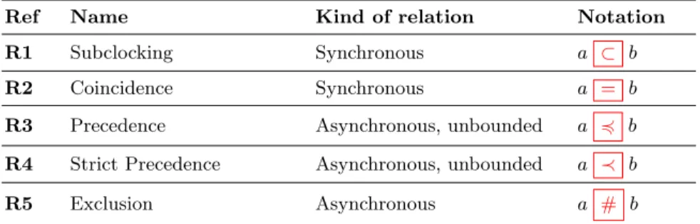
Table 1. Basic relations defined in the ccsl kernel (a and b are clocks, not instants). Ref Name Kind of relation Notation R1 Subclocking Synchronous a ⊂ b R2 Coincidence Synchronous a = b R3 Precedence Asynchronous, unbounded a 4 b R4 Strict Precedence Asynchronous, unbounded a ≺ b R5 Exclusion Asynchronous a # b
Coincidence According to the considered relation the clocks a and b always tick simultaneously (a = b), it is defined as (∀k ∈ N?)(a[k]≡b[k]).
Subclocking a ⊂ b defines a as being a subclock of its superclock b. Every instant of the subclock occurs synchronously with one of the instants of the superclock: (∀k ∈ N?
Exclusion a # b. The clocks connected with this relation cannot have coinci-dence instants: (∀k ∈ N?)(∀i ∈ N?)(a[k]#b[i]).
Precedence a ≺ b is the index-dependent relation. This operator is un-bounded. Every instant of clock a has to precede the instant of clock b with the same index (∀k ∈ N?)(a[k]≺b[k]).
Strict Precedence a ≺ b. This relation is a severer version of the previous one in the sense that the instants of the clocks a, b with the same indices cannot be equal: (∀k ∈ N?)(a[k]
4b[k]).
4.2 The kernel expressions
A ccsl specification consists of clock declarations and conjunctions of clock relations between clock expressions. A clock expression defines a set of new clocks from existing ones. Most expressions deterministically define one single clock. Table 2 gives a list of the ccsl kernel expressions.
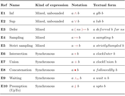
Table 2. Basic expressions defined in the ccsl kernel.
Ref Name Kind of expression Notation Textual form E1 Inf Mixed, unbounded a∧b a glb b
E2 Sup Mixed, unbounded a∨b a lub b
E3 Defer Mixed a(ns) b a def erred b f or ns E4 Sampling Mixed a7→b a sampling b E5 Strict sampling Mixed a→b a strictlySampled b E6 Intersection Synchronous a∗b a clockInter b E7 Union Synchronous a+b a clockU nion b E8 Concatenation Synchronous a•b a f ollowedBy b E9 Waiting Synchronous afnb a wait n b
E10 Preemption (UpTo)
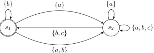
Sampling a 7→ b. The sampling expression ticks in coincidence with the tick of the base clock immediately following a tick of the trigger clock and after it dies. In the considered case, the trigger clock is b and the base clock is a. The textual syntax of this expression is represented as c = a sampling b. In Figure 1 the automaton is given, where input symbol c is equal to the result clock of the expression. The notation {a, b, c} denotes that the automaton remains in state s2 if a, b and c tick all together simultaneously. if b and c tick simultaneously
without a then, the automaton goes back to state s1. If a ticks alone, it stays in
s2. All other cases are forbidden by the semantics of the operator.
s1 s2 {b} {a} {a, b} {b, c} {a} {a, b, c}
Fig. 1. The automaton for sampling expression
Strict Sampling a → b. The expression is a strict version of the previous one where c is emitted when the automaton is in state s1, and a and b tick
simultaneously.
Waiting a fn b. The resulting clock ticks only once after a special number
given as a parameter of the base clock, and then the resulting clock dies. c = a wait n b, where n is a given parameter (it is a natural number).
Preemption (UpTo) a b. The resulting clock ticks in coincidence with a, it dies as soon as b starts to tick: c = a upto b.
Union This expression is non-terminating and index-independent. Its result is a clock with set of instants which is a union of the instants sets of the clocks-parameters that participate in the expression: c = a+b.
Intersection The result of this index-independent expression is the clock which ticks each time when the clocks-parameters tick simultaneously: c = a∗ b.
Concatenation a•b . The expression is terminating. The resulting clock ticks in coincidence with the first clock-parameter a. After death of a it starts to tick in coincidence with the second clock-parameter b . It should be noted that this expression is valid only if the first clock eventually dies, i.e. a ↓ is specified.
Defer (Delay) a(ns) b. The parameter of the expression are a (the base clock), b (the delay clock) and ns that represents a sequence of elements from N>0. The sequence of the natural numbers can have an infinite part. Let ns[i] be
the ith
element of the sequence. We assume that if i > 0 then ns has an infinite part, if 0 6 i < p there are p elements in the sequence. Every tick of the base clock starts up the counter for respective element of the sequence. For every tick of the delay clock the relative counter is decreased. When the counter reaches 1 the respective instant of clock b occurs. The textual form of the expression is c = a def erred b f or ns.
Sup a ∨ b. The expression is index-dependent. The expression a ∨ b defines a clock that is slower than both a and b and whose kth tick is coincident with the later of the kth ticks of a and b. The formal definition is presented as:
(a 4 (a ∨ b))(b 4 (a ∨ b))(∀c ∈ C) : (a 4 c)&(b 4 c) ⇒ ((a ∨ b) 4 c). This is a typical example of unbounded transition system (with an infinite number of states). s0 s1 . . . s−1 . . . {a} {b} {a, b, c} {a} {b, c} {a, b} {b, c} {a, b} {a, c} {b} {a, b} {a, c} {a, b}
Fig. 2. The automaton for sup expression
Inf a∧b. This is index-dependent and unbounded. It is the dual of the previous one. The result of the expression is the slowest of faster clocks. It means that the defined clock is faster than both a and b , the kthtick of this clock occurs in coincidence with the earlier of the kth ticks of both a and b. ((a ∧ b) 4
a)((a ∧ b) 4 b)(∀c ∈ C) : (c 4 a)&(c 4 b) ⇒ (c 4 (a ∧ b)) is the formal definition.
4.3 Unbounded CCSL operators
Lazy evaluation or call-by-needed is an evaluation strategy that delays the eval-uation of an expression until its value is actually needed. This approach allows construction of potentially infinite data structures and avoids repeated evalua-tions. To construct the algorithm of the parallel execution of several automata, it is necessary to have the possibility to work with infinite data structures (transi-tion systems with an infinite number of states). Lazy evalua(transi-tion provides the ap-paratus for this task. The ccsl has four basic unbounded operators which can be
represented as infinite automata: the precedence relation, the strict precedence relation, the inf expression (the fastest of slower clocks) and the sup expression (the slowest of faster clocks).
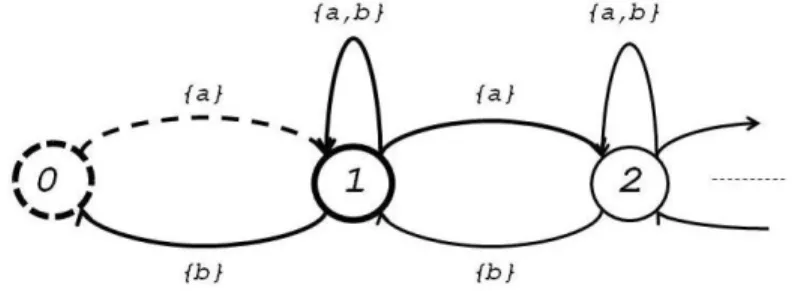
Example 1. Let us consider as an example the automaton for the strict precedence relation (Fig. 3).
Fig. 3. The automaton for strict precedence relation
If we only consider the possible outgoing transitions of each state, we can distinguish the initial state (0 on Fig. 3) from the other ones. In the initial state, only a can tick and must tick alone. In the other states, if a ticks alone, we must progress to the right (increasing an unbounded counter), if b ticks alone, we must go back to the left (decreasing the counter). If a and b tick simultaneously, we remain in the same state. We assume that each state has a default transition to itself, when nothing happens.
5
The synchronized product: an algorithm
We assume that the input for the algorithm is a given finite set of automata; each of them can be either finite or infinite. The output is the automaton that is the composition of the input ones. We denote the resulting automaton through the tuple R. Let us introduce the set St which is the set of all unconsidered states of the resulting automaton. At the beginning of the algorithm execution, the initial states of input automata are considered as the current ones. The first unconsidered state of the resulting automaton is the state formed from current ones. For each considered current state of input automata the set of available transitions from the given state is calculated. For all input symbols of each of the calculated transitions the consistent solution is computed, which is the set such that every original symbol is its subset. If the solution exists, the new state is calculated from the states of input automata, in which we can go on the appropriate input symbols that are the subset of the found solution. If the computed new state does not belong to St, it is added to the set of unconsidered states. The resulting automaton is completed by the new state
and the appropriate transition, which has the input symbol that is equal to the respective solution. If the solution cannot be found, then we take a state from St, in the input automata the appropriate states are considered as current. The process is repeated while the set St is not empty.
5.1 The Formal Definitions
We introduce the formal definitions that are used to describe the algorithm. C is the (finite) set of clocks and —C— is its cardinality;
state : C → StateDomain = {ST ALL, T ICK, DEAD} that denotes the state of a clock.
A = {Ai}: the ordered set of input automata for the composition.
Ai= (Ci; Si; Ii; moveOni; si0∈ Si; curi∈ Si; availT ransi), where
Ci⊂ C: the ordered set of clocks of the ith automaton;
Si: the set of states of the ithautomaton;
si0∈ Si: the initial state of the automaton;
moveOni: Si× 2Ci → Si is the transition function;
curi∈ Si: the current considered state;
availT ransi : Si→ 22 Ci
: gives a set of available configurations for a given state. The resulting composite automaton can be defined as follows:
R = (C; SR; moveOnR; s0R∈ SR; curR∈ SR; availT ransR), such that:
C: the set of clocks of the composite automaton is equal to the set of global clocks;
SR = {sR : sR = (s1, ..., s|A|), si ∈ Si, ∀i = 1...|A|}: each element of the set of
states of the resulting automaton consists of the states of input automata; the element of the considered composite state corresponds to the automaton with the same number;
moveOnR: SR×2C → SRis the transition function for the resulting automaton;
s0R∈ SR: the initial state;
curR∈ SR: the current considered state;
availT ransR : SR→ 22 C
: this function returns the set of input symbols for the available transitions of the composite automaton.
The set of found solutions is represented by the set SOL = {sol : sol = (st1, . . . , st|C|), sti∈ {ST ALL, T ICK, DEAD}, ∀i = 1...|C|}.
St = {sR: sR∈ SR} is the set of considered states of the resulting
automa-ton.
Get : Set → element, element ∈ Set: the function that returns an element of the given set.
Register : C × {1..|A|} → 2C. This function returns an input symbol for the
ith automaton based on the states of the global set clocks.
index : 2C
× C → N, the position of a clock in an ordered set of clocks.
5.2 The Composition Algorithm Global variables.
indexTable:=0: indexTable ∈ N;
array StateDomain temp[]: ∀i ∈ {0, ..., |C|-1}, temp[i] ∈ StateDomain; array StateDomain cur_sol[]: ∀i ∈ {0, ..., |C|-1}, cur_sol[i] ∈ StateDomain; array StateDomain OptionsTable[][]: ∀j ∈ {0, ..., |C|-1}, ∀i ∈ {0, ..., 3|C|-1},
OptionsTable[i][j] ∈ StateDomain;
array Boolean SolutionsTable[][]: ∀j ∈ {0, ..., |A|-1}, ∀i ∈ {0, ..., 3|C|-1}, SolutionsTable[i][j] ∈ {true, false};
cur_solution ∈ SOL new stR ∈ SR
The main purpose of the following function is to build the composite au-tomaton from the given set of the input ones. It uses three other functions: buildSolutions(), getSolutions() and buildOptionsTable().
function composition(){
// the initial state is the cartesian product of all the initial states 1. s0R:= s00 × ... × s |A|−1 0 ; St:={s0R}; 3. while(St6= ∅){ 4. curR:=GetElement(N); 5. SOL:=buildSolution(curR);
6. while(SOL6= ){ //for each solution 7. cur_solution:=Get(SOL);
// set clocks to the appropriate states
8. for(k:=0; k<|C|; k:=k+1){ C[k]:=cur_solution[k]; }
//form a composite state from the states of the input automata in which // it is possible to go with the respective input sets
9. for(i:=0; i<|A|; i:=i+1){ new_sti := moveOn(curi, Register(C,i)); }
// include the new created state if it is not yet included 10. if(new_stR ∈ S/ R){
11. SR:=SR∪new_stR;
12. IR:=IR∪cur_solution;
13. }
//include the created state in the set of unconsidered states 14. if(new_stR∈ St){ St:=St ∪ new_st/ R; }
//set the current states to the previous positions 15. for(i:=0; i<|A|; i:=i+1){ curi:=curR[i]; }
16. SOL:=SOL cur_solution; 17. }
18. N:=N curR;
19. } }
The following function calculates the set of possible solutions. It builds a table of all options (OptionsTable) for the states of the clocks. The number of rows of this table is equal to 3|C| . The base is equal to three because all three possible states are considered (ST ALL, T ICK, DEAD). The number of columns is equal to the number of the clocks in the global set. Also, the table for finding solutions is defined (SolutionsTable). The number of rows is equal to 3|C|, the number of columns corresponds to the number of input automata. If the input set defined in a row of OptionsTable is available for the input automaton, then the value of an element of SolutionsTable situated in the same row as the input set is set the value true. When the SolutionsTable is completed (all available input symbols of input automata have been considered), the function getSolutions() is invoked to find the set of solutions SOL using the data of SolutionsTable.
function buildSolutions(sR){
20. buildOptionTable(0);
//Initially there are no solutions 21. for(r:=0; r<3|C|; r:=r+1){
22. for(i:=0; i<|A|; i:=i+1){ SolutionsTable[r][i]:=false; } 23. }
24. for(i:=0; i<|A|; i:=i+1){
// receiving the set of input sets for all available transitions // of the current state of the appropriate ith
// automaton n is a number of available transitions 25. Iin:= availT ransi(sR[i]);
//assignment of the value true to an element of SolutionTable 26. for(k:=0; k<n; k:=k+1){ setMark(Iik) }
27. }
28. return getSolutions(); }
The function based on the values of the completed table of possible solutions (SolutionsTable) determines whether there are solutions.
function getSolutions(){ 29. SOL:=∅;
//for all the rows in SolutionsTable 30. for(r:=0; r<3|C|; r:=r+1){
31. boolean isSolution:=true; 32. for(i:=0; i<|A|; i:=i+1){
// if at least one value in the row of table is equal to false // (it means that the given input set is not available for one // of automata) then the corresponding row of OptionsTable // cannot be considered as solution
33. if(SolutionsTable[r][i]==false) { isSolution:=false; } 34. if(isSolution){ 35. for(k:=0; k<|C|; k:=k+1){ 36. cur_sol[k]:=OptionsTable[r][k]; 37. } 38. SOL:=SOL ∪ cur_sol; 39. } 40. } 41. return SOL; }
The function of building the table for all possible options (OptionsTable). function buildOptionsTable(index){ 42. if(index<0){ 43. temp[index]:=STALL; 44. buildOptionsTable(index+1); 45. temp[index]:=TICK; 46. buildOptionsTable(index+1); 47. temp[index]:=DEAD; 48. buildOptionsTable(index+1); 49. } else{ 50. for(k:=0; k<|C|; k++){ 51. OptionsTable[indexOfTable][k]:=temp[k]; 52. } 53. indexOfTable:=indexOfTable+1; 54. } }
The following function assigns the value true to an element of SolutionsTable. The element corresponds to the current considered input set defined in the table OptionsTable function setMark(Iik){ 55. for(r:=0; r<3|C|; r:=r+1){ 56. boolean isDifferent:=false; 57. for(p:=0; p<|Ii|; p:=p+1){ 58. if(OptionsTable[r][index(Iik[p])]6= Iik[p]){ 59. isDifferent:=true; 60. } 61. } 62. if(!isDifferent){ 63. SolutionsTable[r][i]:=true; 64. } 65. } }
5.3 The Time Complexity of the Algorithm
To determine the complexity of the composition algorithm, it is necessary to determine the time complexity of each of the used functions. Let us consider
the function buildOptionsTable() (lines 42-54). This function is recursive. The recursion depth is determined by the number of clocks in the global set. Thus, the time complexity is equal to 3|C| .
The function getSolutions() has two nested loops. The outer loop (lines 30-40) goes over all rows of the solution table. The number of iterations is equal to 3|C|. The nested loop (lines 32-39) is designed to examine the marked input sets placed in the same row of the corresponding table. Since the number of elements in the row is equal to the number of automata, the number of iterations is |A|. The complexity of the function given by the product is defined as 3|C|× |A|.
The setMark() function is represented by two loops. The number of iterations of the outer (lines 55-65) is equal to 3|C|. The number of iterations of the inner loop (lines 57-60) is determined by the number of elements in the input set of the considered automaton. Because it is equal to the number of clocks involved in the execution of the relevant automaton, the number of repetitions is equal to |Ci|.
We define the complexity of the function for building the set of solutions buildSolutions(). The initialization phase (lines 21-23) is represented by two nested loops, the time complexity of its implementation is equal to 3|C|× |A|. The process of the solutions table completion is presented by lines 24-27. The number of iterations of the outer (line 24-27) is equal to the number of input automata |A|. The number of the repetitions of the first inner loop operations depends on the number of elements which belong to the previously found set of input sets of the available transitions for the considered automaton. The size of the set is marked as n. The total time complexity of the function taking into account the previous results is equal to
D := 3|C|× |A| + 3|C|× |A| + 3|C|+ |A| × n × 3|C|× |Ci| (1)
The complexity of the developed algorithm can be computed on the basis of our results. The initialization of the initial state of the resulting automa-ton requires |A| operations. The cycle through all the unconsidered (lines 3-19) composite states is determined by the number of elements in N , the number of iterations is equal to |St|. In this loop the considered earlier function for build-ing solutions (line 5) is involved. Its complexity is defined as (1). To examine all built solutions, it is necessary to perform a number of iterations which is equal to the cardinal number of the set |SOL|. To assign to all clocks of the global set the corresponding states, it must be |C| operations (lines 8). To form a new composite state (line 9), it is performed |A| repetitions of the loop code. To reset the states of input automata, it is necessary to perform the number of iterations which is equal to the number of input automata. The formula expressing the time complexity of the algorithm is as follows:
|A| + |St|(D + |SOL|(|C| + 2 × |A|)) (2) Since we are considering the worst case in which all the expressions of the clock constraint specification language do not have common clocks, the value n which is equal to the number of all available transitions can be approximated
by the quantity 3|Ci|, since the number of the available transitions is not greater
than the number of all possible combinations of the states of clocks for the con-sidered input automaton. Thus, after the change of the corresponding quantity the representation formula for the time complexity becomes:
|A|(1 + |N |(3|C|(2 + 1 |A|+ 3 |Ci|× |C i|) + |SOL|( |C| |A|+ 2))) (3)
From the obtained result (3) we can conclude that the developed composition algorithm has exponential complexity in the number of clocks involved in the composition.
Additionally, it depends on the number of states in the resulting automaton. When the composition is infinite then the algorithm does not terminate. When the composition is finite, the complexity is exponential in the number of clocks in the worst case.
5.4 The Implementation of the Algorithm
For a software implementation of the algorithm, it is necessary to represent each kind of the built automata in terms of classes and to define the suitable presentation of the correspondent states. There are two types of input automata: finite and infinite. For the latter ones, lazy evaluation is used to compute the next state on demand.
All classes are divided into 5 main, architecturally significant packages: enti-ties, abstractions, states, automata and executors. The entities package contains the primary classes-entities, which are necessary for the implementation of the composition algorithm such as the class for the representation of the clock no-tion, the class for the resulting automaton. The abstractions package stores two main interfaces that specify responsibilities for all automata and states. The states package includes all classes intended to work with states of all kinds of automata. The implementation for all previously formally defined automata for the basic ccsl operators is contained in the automata package. The executors package includes classes-executors that are responsible for organizing the correct interactions of all classes so as to build the synchronized product of the input automata.
6
Conclusion
This work has proposed a data structure based on lazy evaluation to encode the semantics of ccsl operators as transition systems. Then the composition of ccsl operators is computed as the synchronized product of those transitions systems. The underlying definitions were implemented in Java. The automa-ton form representation for basic expressions and relations of the ccsl kernel were proposed. The lazy evaluation was considered and applied for building the unbounded automata of the corresponding operators.
The complexity analysis of the algorithm was conducted. It allowed estimat-ing the time resources needed by the composition algorithm which solves a given computational problem. It was shown that the computational complexity of the developed algorithm is exponential in the number of clocks and is linear with the size of the resulting automaton. Such an automaton can be infinite in which case the (semi)algorithm does not terminate.
However, there are many classical examples where the resulting automaton is finite, and where the actual complexity is much better than the theoretical worst-case computed here. As future work, we intend to qualify useful worst-cases that are tractable in ccsl and therefore would allow model-checking ccsl specifications.
References
1. Andr´e, C.: Syntax and Semantics of the Clock Constraint Specification Language (CCSL). Research Report RR-6925, INRIA (2009)
2. Mallet, F.: CCSL: specifying clock constraints with UML/MARTE. Innovations in Systems and Software Engineering 4(3) (2008) 309–314 The original publication is available at www.springerlink.com.
3. OMG: UML Profile for MARTE, v1.0. Object Management Group. (November 2009) formal/2009-11-02.
4. Benveniste, A., Caspi, P., Edwards, S.A., Halbwachs, N., Le Guernic, P., de Simone, R.: The synchronous languages 12 years later. Proceedings of the IEEE 91(1) (January 2003) 64–83
5. Gascon, R., Mallet, F., DeAntoni, J.: Logical time and temporal logics: Comparing uml marte/ccsl and psl. In: TIME. (2011) 141–148
6. Yin, L., Mallet, F., Liu, J.: Verification of marte/ccsl time requirements in prome-la/spin. In: ICECCS. (2011) 65–74
7. Arnold, A.: Synchronized products of transition systems and their analysis. In: ICATPN. (1998) 26–27
8. Alur, R., Dill, D.L.: A theory of timed automata. Theoretical Computer Science 126 (1994) 183–235
9. Lee, E.A., Messerschmitt, D.G.: Static scheduling of synchronous data flow pro-grams for digital signal processing. IEEE Trans. Computers 36(1) (1987) 24–35 10. Lee, E.A., Parks, T.M.: Readings in hardware/software co-design. Kluwer
Aca-demic Publishers, Norwell, MA, USA (2002) 59–85
11. Arnold, A.: Finite transition systems - semantics of communicating systems. Pren-tice Hall international series in computer science. PrenPren-tice Hall (1994)
12. Arnold, A.: Nivat’s processes and their synchronization. Theor. Comput. Sci. 281(1-2) (2002) 31–36
13. Mallet, F.: Automatic generation of observers from marte/ccsl. In: RSP. (2012) 86–92
14. Julien DeAntoni, Charles Andr´e, R.G.: CCSL denotation semantics. Research Report RR-8000, INRIA (2010)
15. Ptolemy: Synchronous dataflow (February 2011) 16. Wikipedia: Lazy evaluation (December 2012)