DOCTORAT DE
DOCTORAT DE L’UNIVERSITÉ
L’UNIVERSITÉ DE TOULOUSE
DE TOULOUSE
Délivré par :
Discipline ou spécialité :
Présentée et soutenue par :
Titre :
Ecole doctorale :
Unité de recherche :
Directeur(s) de Thèse :
Rapporteurs :
le :
Membre(s) du jury :
Imprimer la couvertureUniversité Toulouse III Paul Sabatier (UT3 Paul Sabatier)
Systèmes (EDSYS)
Reactive Control and Sensor Fusion for Mobile Manipulators in Human Robot
Interaction
vendredi 4 octobre 2013
Wuwei HE
Informatique et Robotique
M. Philippe BIDAUD, professeur
M. Jean-Pierre GAZEAU, ingénieur de recherche
M. Daniel SIDOBRE
LAAS-CNRS
M. Rachid ALAMI, directeur de recherche
M. Philippe FRAISSE, professeur
T
H
ESE
`
en vue de l’obtention du
Doctorat de l’Universit ´e de Toulouse d ´elivr ´e par l’Universit ´e Toulouse III Paul Sabatier
Sp ´ecialit ´e: Informatique et Robotique (Computer Science and Robotics)
pr ´esent ´ee et soutenue publiquement le 4 Octobre 2013
Reactive Control and Sensor Fusion for Mobile
Manipulators in Human Robot Interaction
Wuwei HE
Pr ´epar ´ee au Laboratoire d’Analyse et d’Architecture des Syst `emes sous la direction de M. Daniel SIDOBRE
Jury
M. Philippe BIDAUD Rapporteur
M. Jean-Pierre GAZEAU Rapporteur
M. Philippe FRAISSE Examinateur
M. Patrick DAN `ES Examinateur
M. Rachid ALAMI Examinateur
In order to share a workspace with humans, a service robot should be able to safely interact within an unstructured environment. In this context, the robot shall adapt its behavior and react to the environment changes and human activities. The robots based on motion plan-ning are not able to adapt fast enough, so we propose a reactive trajectory controller to track targets, react to human activities and prevent event like collisions.
The reliability of the proposed trajectory controller is based on recent fusion techniques to identify movements and detect forces associated to events. We propose to employ a 6D force/torque sensor to estimate the inertial parameters of the manipulated objects, then the parameters are used to complement the visual tracking process and to compute the contact forces between the robot end-effector and the environment. The contact forces are ana-lyzed and classified by using learning techniques to detect different events, such as human grasping the object or collision between the object and the environment.
This work, conducted as part of the European projects DEXMART and SAPHARI, and the ANR projects ASSIST and ICARO, has been integrated and validated on the Jido and the PR2 robot platforms of LAAS-CNRS.
Keywords: Robotics, Trajectory control, Sensor Fusion, Machine Learning, Human-Robot Interaction, Manipulation
Afin de partager un espace de travail avec les humains, les robots de services doivent ˆetre capable d’interagir dans des environnements peu structur´es. Dans ce contexte, le robot doit r´eagir et adapter son comportement aux ´evolutions de l’environnement et aux activit´es des humains.L’utilisation de planificateur de mouvement ne permet pas au robot d’ˆetre suffisam-ment r´eactif, aussi nous proposons un controleur de trajectoire r´eactif capable de suivre une cible, de r´eagir aux changement d’atitudes des humains ou de pr´evenir les ´ev`enements et, en particulier, les collisions.
Pour fiabiliser le contrˆoleur de trajectoire, nous utilisons des techniques de fusion de donn´ees r´ecentes afin d’identifier les mouvements ou de d´etecter des forces associ´ees `a des ´ev`enements. Nous proposons d’utiliser un capteur de force six axes pour estimer les param`etres d’inertie des objets manipul´es, puis d’utiliser ces param`etres pour compl´eter le contrˆole visuel et calculer les forces de contact entre l’organe terminal du robot et son environnement. L’utilisation de technique d’apprentissage permet d’analyser et de classifier les forces de contact pour d´etecter diff´erents ´ev`enements tels que la saisie de l’objet par un humain ou le contact entre le robot ou l’objet transport´e et l’environnement.
Ce travail a ´et´e int´egr´e et test´e sur les robots jido et PR2 du LAAS-CNRS dans le cadre des projets europ´eens DEXMART et SAPHARI et des projets ANR ASSIST et ICARO.
Mots cl´es: Robotique, contrˆole de trajectoire, fusion de donn´ees, apprentissage, inter-action homme-robot, manipulation.
This Ph.D program at LAAS-CNRS has been three years of precious experience for me. During these years, I have learned so much, not only about robotics, but also about how to work and especially how to work in a team. Therefore, I would like to express my gratitude, without trying to make a complete list, to the people who have helped me during these years. Foremost, I would like to thank Mr. Daniel Sidobre and Processor Rachid Alami to give me this opportunity to work in a prestigious team and in the promising area of robotics. The always right on-the-spot comments and advices of Rachid have been always a powerful push for the work, and the patience and encouragement from Daniel have always been the most helpful. I am very grateful for these years in this group and it has been an invaluable opportunity in my professional career.
A special thanks goes to Mathieu Herrb and Anthony Mallet, our research engineers, for their support and time. When I firstly arrived, my lack of experience with the systems on the robots may have required much patience. And I would like to thank Jerome Manhes for his work on the Bidule.
Then I would like to thank the Ph.D students and Postdocs with whom I have worked. Much appreciation goes to Xavier Broqu`erer and Mokhtar Gharbi. They have been the most supportive and with whom I have worked the most for the first year. The time we spent together to test the motion planner on the robot was long but fun. Then there are Mathieu Warnier, Mamoum Gharbi, Amit Kumar Pandey, Jim Mainprice ... with whom we have spent the most stressful and sometimes chaotic time on the robots.
Then I would like to say thanks to the other members of the group who are the best friends one could ever have. Special thanks go also to the friends that I know from LAAS and the schools around the LAAS: in INSA, SUPAERO and UPS, with whom I have spent the breaks from work on sports and inspiring discussions on everything.
Then, I thank Jido and PR2, our awesome robots, who have always been very under-standing.
1 Introduction 1
1.1 Introduction . . . 1
1.2 Motivation. . . 2
1.3 Research Objectives and Contribution . . . 3
1.3.1 Sensor Fusion . . . 3
1.3.2 Learning to Manipulate. . . 5
1.3.3 Sensor-Based Control . . . 5
1.4 Structure of this Manuscript . . . 5
1.5 Publication, Software Development, and Research Projects . . . 6
2 Related Work and Background 9 2.1 Introduction . . . 10
2.2 Autonomous Mobile Manipulator . . . 10
2.2.1 Robots at LAAS-CNRS . . . 10
2.2.2 Software Architecture for Human Robot Interaction. . . 12
2.3 Motion Planning and Control . . . 14
2.3.1 Geometrical Constraints in HRI . . . 15
2.3.2 Robot Motion Representation . . . 15
2.3.3 Path Planning . . . 17 2.3.4 Interpolation . . . 19 2.3.5 Trajectory Generation . . . 20 2.3.6 Grasp Planning . . . 22 2.3.7 Trajectory Control . . . 24 2.4 Sensor Fusion . . . 25
2.4.1 Multisensor Data Fusion . . . 25
2.4.2 Force Sensing . . . 25
2.5 Wavelet and Classification . . . 26
2.6 Conclusion . . . 28
3 Force Vision Sensor Fusion 29 3.1 Introduction . . . 29
3.2 Force Sensing . . . 31
3.2.1 Inertial Parameters Estimation . . . 31
3.2.2 Excitation Trajectories . . . 34
3.2.3 Online Object Recognition . . . 36
3.2.4 Contact Forces/Torques Computation . . . 37
3.3 Force-Vision Fusion, a Multi-modal Tracking . . . 38
3.3.1 Process Model for Tracking . . . 39
3.3.2 Measurement Models . . . 41
3.4 Nonlinear Kalman Filtering. . . 43
3.5 Simulation and Experimental Results. . . 47
3.6 Conclusion . . . 49
4 Machine Learning for Manipulation 51 4.1 Introduction . . . 51
4.1.1 Trajectory Control with Continuous Classification . . . 52
4.2 Bidule: a Device for Manipulation Learning . . . 52
4.3 Wavelet Analysis . . . 55
4.3.1 Wavelet Packet Transformation (WPT) . . . 55
4.3.2 Lifting Scheme . . . 57
4.3.3 Feature Formation . . . 59
4.4 Feature Selection . . . 60
4.4.1 Fisher Linear Discriminant Analysis . . . 61
4.4.2 Fisher LDA for Feature Selection . . . 62
4.5 Relevance Vector Machine (RVM) and Classification . . . 64
4.6 Data Acquisition and Results . . . 65
4.6.1 The Experimental Protocol . . . 65
4.6.2 Results and Discussion . . . 66
4.7 Conclusion . . . 70
5 Reactive Trajectory Controller 71 5.1 Introduction . . . 71
5.2 From Path to Trajectory . . . 72
5.2.1 Basic Concepts of the Trajectory Generation . . . 72
5.2.2 Trajectory Generation From a Given Path . . . 76
5.2.3 Application to Robot Manipulators . . . 79
5.2.4 Planning in the Cartesian Space . . . 81
5.3 Control Primitives. . . 83
5.4 Reactive Trajectory Controller . . . 86
5.4.1 Execution Monitoring . . . 87
5.5 Results and Comparison . . . 92
5.6 Conclusion . . . 94
6 Conclusion and perspectives 97 6.1 Conclusion . . . 97
6.1.1 Visual Servoing and Trajectory Based Control. . . 97
6.1.2 Force Sensing and Force Events . . . 98
6.2 Perspectives . . . 98
6.2.1 Sensor Fusion and Learning . . . 98
6.2.2 Trajectory Control . . . 101
A Nonlinear Kalman Filters 103 A.1 Discrete Kalman Filtering. . . 103
A.2 Extended Kalman Filter . . . 104
B Quaternions and Rotations 107 B.1 Axis-Angle Representation . . . 107
B.2 Definition of Quaternion . . . 107
B.3 Rotation matrix . . . 109
B.4 Rotations and Compositions . . . 109
B.5 Perturbations and Derivatives . . . 110
C Wavelet Analysis 113 C.1 Windowed Fourier Transform. . . 113
C.2 Continuous Wavelet Transforms . . . 114
C.3 Discrete Wavelet Transforms . . . 115
D Sparse Kernel Machines 117 D.1 Support Vector Machine . . . 117
D.1.1 Linear SVM . . . 118
D.1.2 The Kernel Trick and Nonlinear SVM . . . 121
D.2 Relevance Vector Machine . . . 121
D.2.1 Evidence Approximation Theory. . . 121
D.2.2 Evidence Approximation . . . 125
Bibliography 127 E R´esum´e en franc¸ais 137 E.1 Introduction . . . 137
E.1.1 Motivation and Contribution . . . 137
E.1.2 Etat de l’Art´ . . . 140
E.2.1 Estimation des param`etres d’inertie . . . 146
E.2.2 Fusion force-vision et suivi multi-modal . . . 151
E.2.3 R´esultats de simulation et exp´erimental pour la fusion . . . 154
E.3 Apprendre pour ´echanger des objets . . . 154
E.3.1 Bidule: un appareil pour apprendre la manipulation . . . 155
E.3.2 Traitement du signal et d´etection d’´ev´enements . . . 157
E.3.3 S´election des caract´eristiques pour la LDA de Fisher . . . 161
E.3.4 Classification et machine `a vecteur de pertinence . . . 162
E.4 Acquisition de donn´ees et r´esultats . . . 163
E.4.1 Le protocole exp´erimental . . . 163
E.4.2 R´esultats et interpr´etations . . . 163
E.4.3 Conclusion . . . 167
E.5 Contrˆoleur de trajectoire r´eactif. . . 168
E.5.1 G´en´eration de trajectoire en ligne . . . 168
E.5.2 Primitives de contrˆole . . . 168
E.5.3 Contrˆoleur de trajectoire r´eactif . . . 171
E.5.4 Modes de contrˆole de trajectoire . . . 172
E.5.5 R´esults et comparaison . . . 175
1
Introduction
The conscious experience of being a subject arises when a single organism learns to enslave itself.
—Thomas Metzinger, The Ego Tunnel: The Science of the Mind and the Myth of the Self
Abstract. As an important part of the effort to achieve a socially aware service robot, the challenges of sensor-based control for interactive object manipulation between robot and human are introduced. The work consists in three distinctive parts: force sensor fusion, event detection by force sensor, and reactive trajectory control. The research objectives, contribution and the outline of work are presented. As this work has been a part of several research projects for service robots, some cooperative work in the team is also included.
1.1
Introduction
While conquering the industrial realm for its multiple advantages over a human operator, the robot manipulator has become a commodity even for enterprises which have made their suc-cess by a business model based on cheap labor, such that Foxconn, an electronics contract manufacturing company, is reported to start to install robot manipulators on their fabrica-tion lines1. The tasks that the industrial robots execute are often predefined in a static and structured environment, thus humans are excluded from the workspace.
1http://www.reuters.com/article/2011/08/01/us-foxconn-robots-idUSTRE77016B20110801
The researchers in service robotics, on the other hand, have already started to work towards the dream of robots living and working around people and inside human society, which has long been a dream in science fiction, being it novels, films, or comics. Although robots with a personality like Bender, or Gort exist still only in fictional works, autonomous automated machines (or simply, robots) have quietly begun to enter our home, such as
Hom-bot of LG, etc. The mobile manipulator as a service robot is not yet available for
households to purchase, but is already a reality in the laboratories all around the world. While serving mainly as research platforms, with promising results being published every year, the optimism about service mobile manipulators can hardly be criticized as a children’s dream anymore. In fact, having a robot companion seems like a step away for the optimists
and the robot fans. They are expected to search and rescue ([Khan 12]), guide people all
around in museums ([Yousuf 12]), and help people in hospitals([Devos 12]). And most
importantly, socialize and learn from us ([Koenig 10], [Argall 09], [Fong 03]). Amongst many research platforms, one example is Justin, a mobile manipulator from DLR, on which
two DLR-LightWeight Robot-III arms are mounted [Ott 06b]. The base has four wheels.
The other example is PR2, the robot developed by Willow Garage. PR2 is fully powered by open source software, with the ROS (Robot Operating System). LAAS-CNRS built a platform called Jido and developed its own software architecture for all its robots. This software architecture has been adapted for the PR2. We will further present our two stars in the next chapter.
1.2
Motivation
Service robots work in a dynamic and unstructured environment, hence it is impossible to model every action a service robot is to achieve. The robot is expected to behave au-tonomously, which may raise numerous challenges. Firstly, decision-making taking into account social and ethical codes among people is not an easy task. This level of interaction
can be called cognitive([Lemaignan 12]). Secondly, working in a changing environment
needs the ability to react. For example, the robot should be able to catch a moving object, react to unpredictable activities carried out by people, and be able to know what is happen-ing at this level. The lower-level interaction, which concerns also a crucial part of security and safety for the agents in the environment and for the robot himself, should also be stud-ied. The emphasize of this thesis is mainly on the lower level of sensor fusion and adaptive control, while being a part of socially aware Human Robot Interaction research projects. More precisely, we focus on the manipulation task of object exchange with human counter-parts, should it be the case of giving an object to a person or the case of taking object given by a person. This work does not claim that cognitive interaction and physical interaction are separate matters (which can be seen as a concept derived from the philosophical dualism), instead, the limits of the document are drawn where the contribution ends.
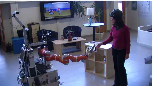
The motivation of this work can be expressed by an analogy: imagine that a person needs to take an object and give it to another person. The environment is dark so they may not always see the object properly (in fact, the vision systems are often unstable and a robot sees things as we see in darkness), and the objects are unknown (heavy or not, which is important for the robot control). And for normal object exchange, the two people are reactive and the manipulation is natural and robust. The giver should predict where the receiver’s hands will be, and will release the object when he detects that the object is firmly grasped. Based on a motion planner provided in our team from colleagues’ work, this thesis sets out to solve this task. Three major parts are proposed: force sensor fusion, continuous classification for events detection, and a trajectory controller. A scenario is given in Figures
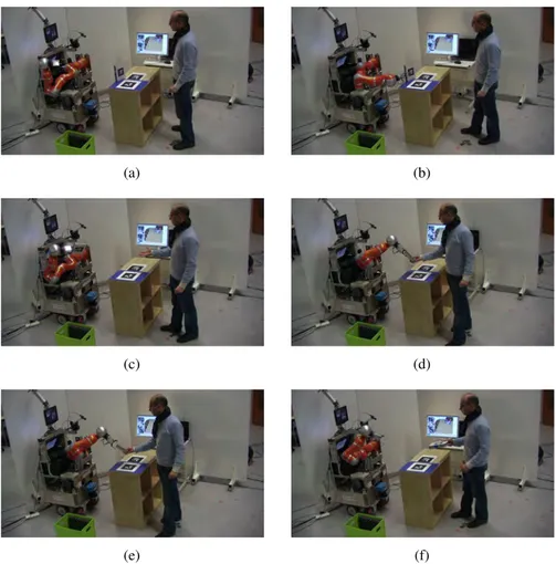
1.1and1.2as an example. In this scenario, the robot shall give an object to a person. The robot needs to grasp the object and give it to the person. When the person grasps the object, the robot should detect it and release the object. The relationships between these different parts can be found in Figure1.3.
Figure 1.1: A typical object exchange task: robot gives an object to human.
1.3
Research Objectives and Contribution
1.3.1 Sensor Fusion
Working in an unstructured environment means that the robot does not always have a model of the environment. The first challenge is through vision, depth sensors, and others, to model the geometry of the environment and update it online. The geometrical modeling and monitoring is based on the work of the colleagues at LAAS. Returning to the object
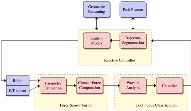
Figure 1.2: When the robot executes the trajectory, it shall estimate the dynamic of the manipulated object, compute the contact forces between the object and human hand, and control the motion to track the exchange point defined in the local frame of the partner’s hand. Parameter Estimation Robot F/T sensor Contact Force Computation
Force Sensor Fusion
Wavelet Analysis Classifier Continuous Classification Trajectory Segmentation Control Modes Reactive Controller Path Planner Geometric Reasoning
Figure 1.3: Relationship of different contributions of this thesis: force sensing, classification and reactive trajectory controller.
exchange task, we deal firstly with the fact that the robot does not have a dynamic model of the object that it is manipulating, and so the robot needs to build the dynamic model of the object. When we see an object that we do not know, we take it, and move it to feel if it is heavy, and whether the mass is homogeneously distributed, or has liquid inside the object. For the robot arm, the information of the dynamics of an object is even more important because the force control of the arm demands a dynamic model of the object. The advantages of the online estimation of the model are numerous and will be stated in the next chapter. Secondly, geometrical precision for the tracking of manipulated objects and human body parts is crucial for the success of the manipulation and for the safety. The fusion of multiple sensors can benefit the perception, and this is one of the objectives of this thesis.
1.3.2 Learning to Manipulate
This work also presents our effort to design an object to teach the robot how to exchange an object with human counterparts. The driving idea is that in a task where the robot is giving an object to a person, the robot should be able to release the object properly while it is grasped by its counterpart. To achieve this, we propose to record human-human object exchange, and then use wavelet analysis of the force sensor signals and use the Relevance Vector Machine(RVM) to build a robust classifier. The model is then transferred to the robot for Human Robot Interaction. The model can also be used to detect other types of collision between the object and environment, which could be used by the controller. In other words, learning the movement and force control law will also be investigated, although not fully studied and experimented.
1.3.3 Sensor-Based Control
When the robot is able to build the dynamic model of the manipulated object, to track the movement of objects and human body parts, and to detect special events, it needs to fin-ish the tasks while reacting to the movement or events. Based on the work of previous colleagues, we propose a trajectory controller to achieve reactive manipulations. The con-troller integrates information from multiple sources, and use online trajectory generation as the central algorithm to track a moving target, grasp the moving object and avoid obstacles. The concept of control primitives is proposed and defined, and all tasks are divided into sev-eral control primitives. These control primitives enable us to define the control strategies for lower-level controllers as position-velocity control or force control.
1.4
Structure of this Manuscript
Following this introduction, this dissertation begins with the presentation of background and literature review on service manipulators, focusing on force sensor fusion, machine
learning, and reactive trajectory control. Then these topics are presented in separated chap-ters. Chapter III presents the problem of inertial parameter estimation, 6D target tracking, and sensor fusion techniques to solve the problems. Chapter IV begins with the problem of frequency information extraction, feature selection, and ends with the Relevance Vector Machine as the classifier. In Chapter V, we present the reactive trajectory controller, with the concept of control primitives and how it is used in human robot interactions. Following the three chapters, we give the discussion and conclusion in chapter VI. Because each chapter deals with a different problem, experimental results are given at the end of each chapter. To keep the reading clear and simple, all the mathematical material about nonlinear filtering, quaternions, wavelet analysis, and RVM learning are in the Appendix for references.
1.5
Publication, Software Development, and Research Projects
Author of this document has participated in several research projects during the thesis. The author contributed to the development of several softwares running on the robots, Jido and Pr2, and maintenance of the robots during the projects:
• Project DEXMART2. DEXMART is a European project for ”DEXterous and
au-tonomous dual-arm/hand robotic manipulation with sMART sensory-motor skills: A bridge from natural to artificial cognition”. DEXMART was a large-scale integrating project, which was funded under the European Community’s 7th Framework Program from 2008 to 2012.
• Project SAPHARI3, Safe and Autonomous Physical Human-Aware Robot interaction,
is a large-scale integrating project which is funded under the European Community’s 7th Framework Program from 2011.
• Project ASSIST (ASSIST: “ ´Etude et d´eveloppement d’un manipulateur mobile `a deux
bras pour l’assistance aux handicap´es”)of the French agency of research ANR.
• Project ICARO4. The objective of the project ICARO is to develop tools to improve
and simplify interaction between industrial robots and humans and their environment. ICARO is funded by the program CONTINT of ANR from 2011 to 2014.
The author developped several softwares during the thesis:
• sensFusion-libs: A C++ library for level sensor fusion techniques, including low-pass filters, Kalman filters, and tools for time-frequency analysis.
• exchange-libs: A C++ library for force events detection, built for mobile manipula-tors. It is based on Sparse Vector Machines (AppendixD).
2http://www.dexmart.eu/ 3http://www.saphari.eu/ 4http://icaro-anr.fr/
• exchange-genom: A GenoM module5for force events detection. The sensor interface is designed for 6D force/torque sensor and for estimated wrist force/torque.
The author participated in the development of several other softwares:
• softMotion-libs: A C++ library for online trajectory generation. It can be tested in the
MORSE, the Modular OpenRobots Simulation Engine6.
• lwr-genom: A GenoM module for the control of the KUKA LWR arm of robot Jido. • pr2-softController: Together with soft-controllers, it provides a bridge between ROS
and GenoM modules, offering trajectory execution for the PR2.
• move3d: The grasp planner is integrated in move3d, which is a generic platform for motion planning7.
• Softwares for Bidule: Bidule is an “intelligent” sensorized device to record human-human object exchange.
Most of the softwares listed above are accessible in robotpkg8. Publication during the thesis (other publications are submitted) :
• WUWEIHE, DANIEL SIDOBRE ANDRANZHAO, A Reactive Trajectory Controller for Object Manipulation in Human Robot Interaction, The 10th International Con-ference on Informatics in Control, Automation and Robotics (ICINCO), Reykjavik, Iceland, 2013
• DANIELSIDOBRE ANDWUWEIHE, Online Task Space Trajectory Generation, IROS 2012 Workshop Robot Motion Planning Online, Reactive, and in Real-time, invited paper.
• WUWEIHE ANDDANIEL SIDOBRE, Sigma-Point Kalman Filter for Dynamic Force
Sensing during Human-Robot I nteraction Manipulation. 13e Colloque National de AIP-PRIMECA, D´emarche et innovation dans la conception et la production des syst`emes int´egr´es, Mont Dor´e, 2012
5https://softs.laas.fr/openrobots/wiki/genom 6http://www.openrobots.org/wiki/morse/ 7https://softs.laas.fr/openrobots/wiki/move3d 8http://robotpkg.openrobots.org/
2
Related Work and Background
There is no fixed physical reality, no single perception of the world, just numerous ways of interpreting world views as dictated by one’s nervous system and the specific environment of our planetary existence.
—Deepak Chopra
Abstract. This chapter presents an overview of research and development in areas re-lated to this thesis: mobile manipulator, force sensing, wavelet analysis, feature extraction and machine learning, reactive trajectory control and more. For the literature review, al-though closely related by the application of object exchange between robot and human, a division is made according to the different research areas. The theoretical backgrounds for those areas are large and diverse, so we do not intend to cover all but focus more on appli-cations. As the work presented in this thesis is achieved during several cooperative research projects, the document will be easier to understand only after the background and related work have been presented. For this reason, the theoretical background for several related areas are briefly introduced, including geometrical reasoning, path planning, and software architectures for mobile manipulators.
2.1
Introduction
Service robots, which work in environments like home, hospital and schools with human presence raise challenges on many aspects. Since the tasks for the robot to realize will not be predefined, they are planned for the new situations that the robots have to handle. Clearly, purely motion control with predefined trajectories will be not suitable for these situations. The robot should acquire ability to react to the changing environment. Before presenting the main background of our developments, several aspects need to be discussed and be compared to the state of the art: architecture for autonomy of a service robot, force sensor fusion during physical HRI, machine learning for events detection during a task, trajectory generation and control, including online adaptation and monitoring. In this chapter, we will give a brief review for all of these aspects, starting with the more general problem of physical Human Robot Interaction (HRI).
2.2
Autonomous Mobile Manipulator
Service mobile manipulators have been developed during recent years in many laboratories all around the world, aiming to achieve assistance robots for daily or work tasks for human. Some of the robots are designed to achieve alone complex tasks in social environment. This section gives a short present of the robots at LAAS-CNRS, and some research accomplished with these platforms. Although not a part of contribution of this thesis, the review of the research areas is considered necessary to understand this dissertation.
2.2.1 Robots at LAAS-CNRS
Mobile manipulators have been developed recent years as platform of research for human robot interactions. For example, Justin [Ott 06a] is a robot of the Institute of Robotics and
Mechatronicsof DLR, the German Aerospace Center, and Rosie is fromTechnische
Univer-sit¨at M¨unchen, (TUM), which is composed of two KUKA-lightweight LWR-IV arms. In
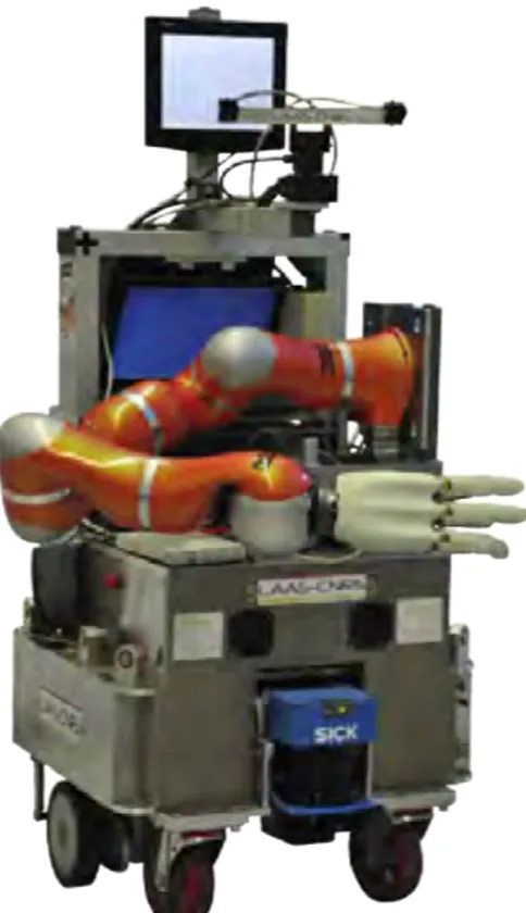
LAAS-CNRS, robot Jido (Figure2.1) has been developed, built up with a Neobotix mobile
platform MP-L655, a Kuka LWR-IV arm, and a Schunk SAH hand of four fingers. The robot arm has an integrated estimator of external torques on each joints. Figure2.2presents the important components on the robot, including a 3D vision system and a Kinect for human motion monitoring.
The second mobile manipulator at LAAS is a PR2 (Personal Robot 2) (Figure2.3), from
Willow Garage 1, which is a robotics research lab and technology incubator devoted to
developing hardware and open source software for personal robotics applications. The robot
is an open platform based on ROS (Robot Operating System)2as the middleware. Software
1http://www.willowgarage.com/pages/pr2/overview 2http://www.ros.org
Figure 2.1: Jido, robot developed at LAAS-CNRS Motion Capture 3D Model (spark) Kinect (niut) 3D-Vision (viman) Kuka LBR-IV (lwr)
Pan-tilt Stereo Head (platine)
Robot Base (jloco)
Figure 2.2: On Jido, the Kinect monitors the human movement, a 3D vision system is mounted on a platine. The robot model of the scene is displayed on the wall-screen.
modules of type GenoM have been successfully used together with ROS, which enables the same softwares for Jido to work on PR2. Although the arms of the PR2 have seven DOF,
it is not equipped to estimate the external torques on joints, neither with the force/torque on wrist.
Figure 2.3: PR2, robot developed by Willow Garage
2.2.2 Software Architecture for Human Robot Interaction
The robots capable of doing HRI must realize several tasks in parallel to manage
vari-ous information sources and complete tasks of different levels. Figure2.4shows the
pro-posed architecture where each component is implemented as a GENOM module. GENOM
[Fleury 97] is a development environment for complex real time embedded software.
At the top level, a task planner and supervisor plans tasks such as cleaning the table, bring an object to a person, and then supervises the execution. The module SPARK (Spatial Reasoning and Knowledge) maintains a 3D model of the whole environment, including objects, robots, posture and position of humans [Sisbot 07b]. It manages also the related geometrical reasoning on the 3D models, such as evaluating the collision risk between the robot parts and between the robot and the environment. An important element regarding SPARK that produces cost maps, which describe a space distribution relatively to geomet-rical properties like human accessibility. The software for perception, from which SPARK updates the 3D model of the environment, are omitted here for simplicity. The module runs at a frequency of 20Hz, limited mainly by the complexity of the 3D vision and of the
Figure 2.4: Software Architecture of the robot for HRI manipulation. Tmis the main tra-jectory calculated initially by MHP. The controller takes also costs from SPARK. The con-troller sends control signals in joint (q in the figure) to the robot arm concon-troller, and during the execution, the controller returns the state of the controller (s) to the supervisor
perception of human.
Another important module, MHP (Motion in Human Presence), integrates path and
grasp planner. RRT (Rapidly exploring Random Tree) and its variants [Mainprice 10] are
used by the path planner. The paths could be described in Cartesian or joint spaces de-pending on the task type. From the path defined as a broken line, an output trajectory is computed to take the time into account. MHP calculates a new trajectory each time the task planner defines a new task or when the supervisor decides that a new trajectory is needed to react to the changes of the environment.
between planning and execution, producing slow reactions and movements because of the time needed by the complex path planner. Furthermore, if object or human moves during the execution of a trajectory planned by the module MHP, the task will fail and so a new task or a new path needs to be planned. The human counterpart often finds the movement of the robot unnatural and so not intuitive to interact with.
To overcome the problem of unnecessary replanning, we designed a reactive controller based on trajectory generation, which lies between the high-level software and the low-level controller. The trajectory controller runs at 100 Hz, an intermediate frequency between the one of the MHP planner and the one of the fast robot servo system at about 1kHz. This trajectory controller allows the system to adapt faster the trajectory to the environment changes. The basic logic behind this work is that, not every type of situation changes needs a replanning of path, or even task, which are all resource consuming. The concept is given as Figure2.5.
The controller integrates information from other modules in the system, including geo-metrical reasoning and human aware motion planning. The related work of these two parts is presented in the following.
Robot Controller Trajectory Control
MHP
Figure 2.5: Trajectory Controller as an intermediate layer in the software architecture, the servo system on robot is fast, while task planning and path planning are slow.
2.3
Motion Planning and Control
We present firstly the basic notions for geometrical constraints in Human Robot Interaction. Then we discuss the motion of a rigid body in space, then we introduce the techniques of motion planning and control for the mobile manipulators.
2.3.1 Geometrical Constraints in HRI
The presence of humans in the work space of a robot imposes new constraints for the mo-tion planning and control for the navigamo-tion and manipulamo-tion of a robot. This field has been studied at LAAS-CNRS. Among the constraints, the more important are the security, visibility and comfort of human counterpart, two of which are illustrated in Figure2.6.
For robot motion, the workspace could be associated to many cost maps, each computed by a type of constraint. The first constraint is computed by distance and mainly to guarantee the safety and security of people at motion planning and robot control. In this case, only distance is taken into consideration. This constraint keeps the robot far from the head of a person to prevent possible dangerous collision between the robot and the person. The theory from [Hall 63] shows that the sensation of fear is generated when the threshold of intimate space is passed by other people, causing insecurity sentiments. For this reason, the cost near a person is high while is zero when distant from him.
The second constraint is called visibility, this is to limit firstly the surprise effect to a person while robot is moving nearby. Secondly, a person feels less surprised when the robot
is moving in the visible zone, and feels more comfortable and safe.[Sisbot 07a]. While
doing robot motion control, this constraint is used to determine if the person is paying attention to the object exchange or not.
Other constraints are also used, which can be found in [Sisbot 07a] and related publi-cations. For example, while planning a point in space to exchange object, this point should be reachable by the person, computed by the length of his arm, and if reaching to this point would produce a confortable posture for the person. A cost of comfort is also computed for every human posture [Yang 04].
When all the cost maps are computed, they are combined by:
c(h, x) = N
∑
i=1wici(h, x)
in which h is the posture of human and x represent the three-dimensional space in which the cost maps are computed. This combined cost map is used during the motion planning and also for the controller, which is part of the contribution of this thesis.
2.3.2 Robot Motion Representation
We firstly consider the kinematics of a rigid body in a 3D space. Considering a reference frame, Fw, which can be defined as an origin Owand an orthogonal basis (Xw,YW, Zw). A rigid body B is localized in 3D space by a frame FB, as shown by Figure2.7.
Translations and rotations shall be used to represent the relation between these two frames. For the translation, Cartesian coordinates are used, but for rotations, several choices are available:
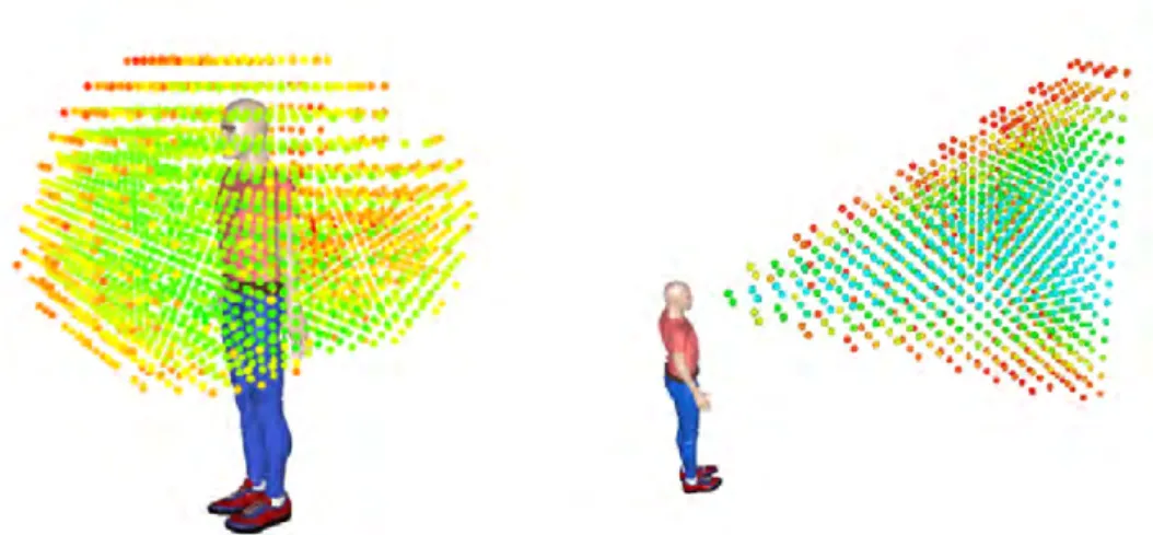
Figure 2.6: Left: 3D reachability map for a human. Green points have low cost, meaning that it is easier for the human to reach, while the red ones, having high cost, are difficult to reach. One application is that when the robot plans to give an object to a human, an exchange point must be planned in the green zone. Right: 3D visibility map. Based on visibility cost, the controller can suspend the execution if the human is not looking at the robot.
Figure 2.7: Rigid body localization in 3D space
• Axis-angles
• Rotation matrices
• Quaternions
The Homogeneous transform matrices are often used to represent the relative displacement between two frames in computer graphics and robotics, because they allow common opera-tions such as translation and rotation to be implemented as matrix operaopera-tions. The
displace-ment from frame FW to frame FBcan be written as: TFB FW = x R3×3 y z 0 0 0 1 (2.1)
In which, R3×3 is the rotation matrix, and x, y, z represents the translation. Given a point b which is localized in local frame FB:
BP
b= [XbYbZb1]T
And TFW
FB represents the transformation matrix between frame FBto FW, then the position of
point b in frame FW is given as:
WP
b= TFFWB
BP b
If a third frame is given as FD, and the composition of transformation matrix is also directly given as: TFD FW = T FB FWT FD FB
Other representations used in this thesis are quaternion and vector plus axis, the details of which is given in Appendix. Readers can also refer to the literature such as the book of Siciliano [Siciliano 08] for more comparison and discussion on different types of represen-tations on rorepresen-tations and transformations.
2.3.3 Path Planning
Through this thesis, the robot is assumed to operate in a three-dimensional space (R3),
called the work space (W ). This space often contains obstacles, which are rigid bodies and also considered geometrical, written asW Oi, in which i means it is the ithobstacle. And the free space is thenWf ree=W \
S
iW Oi, and \ is the subtraction operator. Motion planning
can be performed in working space also configuration spaceQ, or called C-space (Figure
2.8), the set of all robot configurations. Configurations are often written as q and geometry in Cartesian space as x. (It should be noticed that q is also used as to represent quaternions.) Then the obstacles in the configuration space correspond to configurations where the robot is in collision with an obstacle in the workspace.
A path is a continuous curve. It can be defined in the configuration space or workspace (planning in Cartesian space). Path is different from trajectory in that path does not con-sider time. Given a parameter u ∈ [umin, umax], often chosen such that u ∈ [0, 1], a path in configuration space is defined as a curveP such that:
Figure 2.8: Configuration Space and a planned path in C space.
Path planning has been one of the essential problems in robotics. Among numerous pa-pers and books, we have chapter V of Handbook of Robotics, by Kavraki and LaValle
[Kavraki 08] which provides an introduction to this domain, and the book of LaValle [LaValle 06],
in which numerous methods are presented. Figure2.9shows an example of the result of
path planning, which gives a series of points in the configuration space, linking points qI and qF.
Figure 2.9: Results of path planning (by diffusion) as a series of points in the configuration space. The result is in black.
When the robot shares the workspace with humans, the path planner must take into account the costs of HRI constraints. We perform this planning with the T-RRT method
[Jaillet 10] which takes advantage of the performance of two methods. First, it benefits
from the exploratory strength of RRT-like planners [LaValle 01] resulting from their expan-sion bias toward large Voronoi regions of the space. Additionally, it integrates features of stochastic optimization methods, which apply transition tests to accept or reject potential states. It makes the search follow valleys and saddle points of the cost-space in order to compute low-cost solution paths (Fig.2.10). This planning process leads to solution paths with low value of integral cost regarding the costmap landscape induced by the cost func-tion.
In a smoothing stage, we employ a combination of the shortcut method [Berchtold 94]
Figure 2.10: T-RRT constructed on a 2D costmap (left). The transition test favors the exploration of low-cost regions, resulting in good-quality paths (right).
P(s) (with s ∈ R+) is iteratively deformed by moving a configuration q
perturb randomly
selected on the path in a direction determined by a random sample qrand. This process
creates a deviation from the current path, The new segment replaces the current segment if it has a lower cost. Collision checking and kinematic constraints verification are performed after cost comparison because of the longer computing time.
The path P(s) computed with the human-aware path planner consists of a set of via
points that correspond to robot configurations. Via points are connected by local paths (straight line segments). Additional via points can be inserted along long path segments to enable the path to be better deformed by the path perturbation method. Thus each local path is cut into a set of smaller local paths of maximal length lmax.
2.3.4 Interpolation
A path planner gives path as a set of points. To link these points, an interpolation needs to be computed. Interpolation computes the evolution of the coordinates between two positions in space. For translation in Cartesian space, linear interpolation between two positions PB and PCis simply given as:
P(u) = PB+ u.(PC− PB)
where 0 ≥ u ≥ 1 is the interpolation parameter. The interpolation of orientations is then more complicated; we can use quaternions or axis-angle representation. Several choices exist for the quaternion interpolation: LERP, SLERP, and NLERP. The easiest way to inter-polate between two points is the linear interpolation (LERP). Given the starting point as q0, ending point q1, and the interpolation parameter u, LERP(q0, q1, u) yields for each u a point along the straight line connecting the two points:
This interpolation gives points, which are not on the unit sphere. SLERP is LERP but performed on the unit sphere [Shoemake 85]:
SLERP(q0, q1, u) = sin(1 − u)Ω sinΩ q0+ sin(uΩ) sin(Ω) .(q1− q0) Or written as: SLERP(q0, q1, u) = q1(q−11 q2)u (2.3)
For the trajectories in this thesis, the interpolation is performed with axis-angle representa-tion, passing through quaternions. Between point P0and P1, the displacement from P0to P1 can be written as:
Dep0→1= [P(u), a0,1V0,1]
In which, P(u) is the translation interpolation, and the rotations are firstly transformed to quaternion, interpolated in quaternion, then transformed to homogeneous matrix for appli-cations of robot control in Cartersian space.
2.3.5 Trajectory Generation
Trajectory generation computes the time evolution for the robot, in joint space or Carte-sian space. Trajectories are then provided as the input to the controller. Trajectories are important because they enable the system to ensure:
• feasibility: the motion can be verified to respect the dynamic constraints of lower-level controllers.
• comfort: the trajectories can be limited on acceleration and jerk to guarantee the comfort for humans.
• optimization: global optimization can be achieved, depending on the objectives.
2.3.5.1 Trajectory Types
Trajectories can be classified as several categories ( Figure2.11). Mono-dimensional tra-jectories correspond to tratra-jectories for systems of only one degree of freedom (DOF), while
Multi-dimensionalfor more than one DOF. Compared to the case of mono-dimension, the
difficulty for multi-dimensional trajectories is the possible need to synchronize different axis in time. There are point-to-point trajectories, the generation of which are to link two points with a trajectory, and multi-points trajectories, which need to pass through points in the middle too.
From another point of view, trajectories can be planned in joint space or Cartesian space. Joint space trajectories have several advantages:
• Trajectories planned in joint space can be used directly to lower-level controllers without need to compute inverse kinematics.
• No need to deal with the redundant joint or singularities of 7 DOF manipulators or mobile manipulators.
• The dynamic constraints, like maximum acceleration on joints, can be considered while generating the trajectories. While planning in Cartesian space, this should be tested after inverse kinematics.
Figure 2.11: Categories of trajectories [Biagiotti 08]
Cartersian space trajectories may produce natural and more acceptable results for peo-ple. One example is that to give an object to a person, a trajectory planned in Cartersian space can produce a straight-line movement, which is not easy to guarantee while planned in joint space. The advantage of Cartesian space planning is more evident when the robot needs to manipulate a cup of tea, for example, without spitting it out.
Trajectories can be planned on-line and off-line. This thesis tries to achieve reactive robot control, so only on-line is suitable for the trajectory control level.
2.3.5.2 Trajectory Generation Algorithms
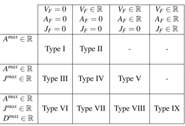
Trajectory generation for manipulators have been discussed in numerous books and papers, among which readers can find [Brady 82], [Khalil 99] and [Biagiotti 08]. Kroger, in his book [Kroger 10b], gives a detailed review on on-line and off-line trajectory generation. Kroger gives a classification of trajectories as in table2.1[Kroger 10b]. For each type in the table, the initial and final condition for velocity and acceleration are arbitrary. The final conditions for velocity, acceleration and jerk are noted as VF, AF, and AF, respectively. Types defined in this table are used in this document.
Our approach to build the controller capable of controlling a complete manipulation tasks is based on Online Trajectory Generation. More results on trajectory generation for
Table 2.1: Different types for on-line trajectory generation VF= 0 VF ∈ R VF ∈ R VF ∈ R AF = 0 AF= 0 AF∈ R AF∈ R JF = 0 JF = 0 JF = 0 JF ∈ R Amax∈ R Type I Type II - -Amax∈ R
Jmax∈ R Type III Type IV Type V
-Amax∈ R
Jmax∈ R Type VI Type VII Type VIII Type IX
Dmax∈ R
robot control can be found in [Liu 02], [Haschke 08], and [Kr¨oger 06]. Kroger proposed algorithms to generate type III trajectories in table2.1. Broquere et al. ([Broquere 08b],
[Broquere 08c]) proposed type V trajectories, with arbitrary final velocity and acceleration.
The difference is important because in this thesis, the controller needs to generate trajecto-ries to join points with arbitrary velocity and acceleration. The details of the algorithm used are given in chapter V to help the readers to understand the document.
2.3.6 Grasp Planning
To plan tasks of picking an object or giving an object to a person, a grasp planner must produce valid grasps on the object. The grasp planner used in this work is based on
previ-ous work at LAAS, presented in [Bounab 08] and [Saut 12]. The proposed approach does
not rely exclusively on a heuristic that can introduce a bias on how the object is grasped. Our objective is to build a grasp list to capture the variety of the possible grasps. The path planner chooses among all the grasps, even in a cluttered environment, for an object with a complex shape. In the following, we illustrate the method with the Schunk
Anthropomor-phic Hand (SAH) depicted on Fig.2.12as it is the one used in our laboratory. It has four
fingers. Each finger has four joints except the thumb. Only the three first joints are actuated, the last one being coupled with the third one. The thumb has an additional joint to place it in opposition to the other fingers.
A single grasp is defined for a specific hand type and for a specific object. The object model is supposed to be a triangle mesh: A set (array) of vertices (three coordinates) and a set of triangles (three indices in the vertex array). It is assumed to be a minimum consistent i.e.has no duplicate or isolated vertices nor degenerate triangles.
2.3.6.1 Grasp Definition
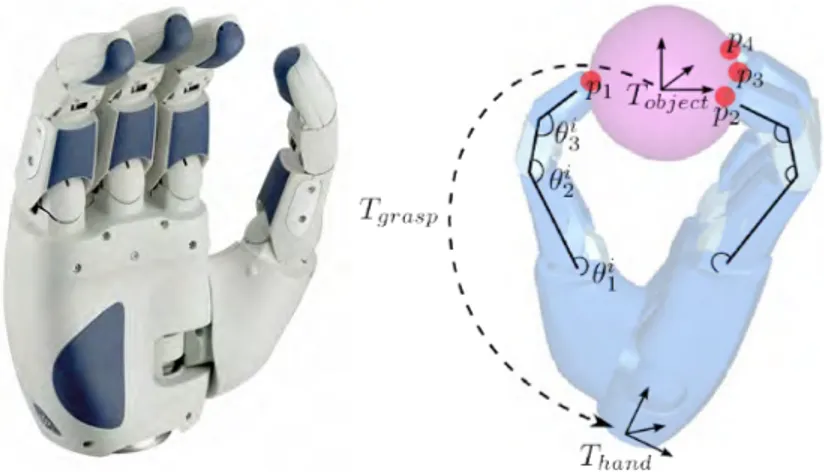
Figure 2.12: Left: The Schunk Anthropomorphic Hand used to illustrate our grasp planning
method. Right: A grasp is defined by a transform matrix Tgrasp= T
ob ject
hand , the finger joint parameters of each finger i (θi
1, θ2i, . . .) and a set of contact points (p1, p2, . . .).
• A transform Tgraspbetween the object and the hand frame.
• A set of finger joint parameters (θ1i, θ2i, . . .) where i is the ID of the finger.
• A set of contact points (p1, p2, . . .) that can be deduced from the two previous items. A contact contains the following information:
• Position: both a 3D vector and a set (triangle index + barycentric coordinates) to store the position.
• Normal: the plane normal of the triangle the contact belongs to. • Coulomb friction: used further to compute the grasp stability. • Finger ID: to store which finger is responsible of the contact.
• Curvature: it is interpolated from the curvature of the vertices of the triangles. As the main concern of the grasp planner is motion planning, it is not possible to rely on the computation of a simple grasp or to compute grasps according to a heuristic that could introduce a bias on the choice of the grasp. It is preferable to compute a grasp list that aims to reflect the best the variety of all possible grasps of the object. Our algorithm applies the following steps that will be detailed further:
• Build a set of grasp frame samples.
• Compute a list of grasps from the set of grasp frames. • Perform a stability filter step.
• Compute a quality score for each grasp. More details can be found in the cited papers.
2.3.7 Trajectory Control
Reactive controller for object manipulation is a research topic that is part of the fundamen-tals of robotic manipulation. Firstly, trajectory generation based approaches where devel-oped. In [Buttazzo 94], results from visual system pass firstly through a low-pass filter. The object movement is modeled as a trajectory with constant acceleration. On this basis, catch-ing position and time is estimated. Then a quintic trajectory is calculated to catch the object, before being sent to a PID controller. The maximum values of acceleration and velocity are not checked when the trajectory is planned, so the robot gives up when the object moves too fast and the maximum velocity or acceleration exceeds the capacity of the servo con-troller. In [Gosselin 93], inverse kinematic functions are studied, catching a moving object is implemented as one application, a quintic trajectory is used for the robot manipulator to joint the closest point on the predicted object movement trajectory. The systems used in those works are all quite simple and no human is present in the workspace. A more recent work can be found in [Kr¨oger 12], in which a controller for visual servoing based on Online Trajectory Generation (OTG) is presented. The results are promising.
Secondly, the research area of visual servoing provides also numerous results, a survey
of which were presented by Chaumette and Hutchinson [Chaumentte 06], [Chaumentte 07]
and a comparison of different methods can be found in [Farrokh 11]. Classical visual ser-voing methods produce rather robust results and stability and robustness can be studied rigorously, but they are difficult to integrate with a path planner, and could have difficulties when the initial and final positions are distant.
Another approach to achieve reactive movements is through Learning from Demonstra-tion (LfD). In [Calinon 04] and [Vakanski 12a], points in the demonstrated trajectory are clustered, then a Hidden Markov Model(HMM) is built. Classification and reproduction of the trajectories are then based on the HMM. A survey for this approach is proposed
in [Argall 09]. Although LfD can produce the whole movement for objects manipulation,
many problems may arise in a HRI context as LfD demands large set of data to learn, and the learned control policies may have problem to cope with a dynamic and unpredictable environment where a service robot works.
The controller must be capable of dealing with various data in HRI context. Compared to methods mentioned above, approaches based on OTG have the following advantages:
• The integration with a path planner is easy and allows to comply with kinematic limits like the one given by human safety and comfort.
• The path to grasp a complex moving object is defined in the object frame, making sure that the grasping movement is collision free.
• The trajectory based method allows to create a simple standard interface for different visual and servo systems, so easy plug-in modules can be created.
The controller integrates various information from high-level software, such as SPARK and MHP, which were presented previously in this chapter.
2.4
Sensor Fusion
2.4.1 Multisensor Data Fusion
Multisensor data fusion aims to combine information form multiple sensory data or data derived from different sources. The goal of sensor fusion is to obtain information which in some sense better than the situation where the sources are used separately. Essentially, different sensors have their own limitations and fusion algorithms could improve the tasks that the sensors are to achieve. Multisensor tracking is one of the most important area where sensor fusion is used to improve the tracking results. [Hall 04] defined functional roles of multisensor integration, and a four-level category with fusion algorithms. An introduction can been found in [Llinas 98]. A review on system architectures on sensor fusion is provided
in [Elmenreich 07]. And Smith in [Smith 06] provides a review on sensor fusion for target
tracking, which is also an application for robotics of fusion in this thesis. Luo et al. [Luo 12] gives a review of application on mechatronics, and the classification of techniques according to different application levels. The table is given as 2.2, and several techniques used or compared in this document have been added. It shall be noticed that machine learning can be seen as part of sensor fusion, but it is separated from the estimation in this thesis for clarity.
2.4.2 Force Sensing
The estimation of the inertia parameters and external forces are separately studied in the literature. An off-line estimation of inertia parameters of an attached object on an
indus-trial manipulator is studied by An et al.[C.H.An 88]. The approach uses ordinary
least-squares estimation and predefined trajectories. The excitation trajectories for the
estima-tion is addressed by Swever et al.[Swevers 97]. Many other approaches are proposed, like
[M.Niebergall 01], mainly based on least-square techniques, so they all ignore the errors
in the data. Kubus et all[Kubus 08a] proposed an on-line method based on recursive total
least-squares. Least-square methods are suitable when the inertia parameters are expressed in the force sensor frame. We need the inertia matrix to recognize the object by comparing the inertia parameters with a database of manipulated objects, but its values in the sensor frame are not constant for the same object when the grasp positions or orientations are dif-ferent. For example, grasping the bottom or the center of a bottle, the inertia matrix in the end effector frame is not the same. In this work, we compute the inertia matrix in the ob-ject frame, which change the system to be nonlinear, and same least square method can no longer be used.
Table 2.2: CLASSIFICATION OF FUSION ALGORITHMS
Low level fusion Medium level fusion High level fusion Estimation methods Classification methods Inference methods Recursive:
• Kalman filter
• Extended Kalman filter • Unscented Kalman filter • Particle filters Non-recursive: • Least squares • Weighted average Covariance based: • Cross covariance • Covariance intersection • Covariance union • Parametric templates • Cluster analysis • K-means clustering • Learning vector quantization
• Artificial neural networks • Support vector machine • Relevance vector machine
• Bayesian inference • Dempster-Shafer theory • Expert system
• Fuzzy logic
For the external force sensing, with inertia parameters of the tool or manipulated
ob-ject known, Uchiyama [Uchiyama 85] estimated external forces/torques with an extended
Kalman filter (EKF), which is based on Taylor expansion of the nonlinear system mod-els. Garcia [Garcia 05] proposed a force and acceleration sensor fusion for compliant robot motion control, with a known tool on the manipulator.
2.5
Wavelet and Classification
The problem adressed here is the ability for a robot to detect events from external forces. An object is designed to teach the robot this ability, the problem is then to chose methods to extract features from a time signal and classify different events. Object exchange grasping-releasing synchronization has been studied in various papers. Nagata et al. presented a
solution to exchange objects between a human and a four-fingered hand [Nagata 98]. They
used a 6-axis force/torque (f/t) sensor mounted on each fingertip to control the grasping force and evaluate modifications in human grasp condition. In the domain of cooperative manipulation with humans [Aggarwal 07,Takubo 02], researchers try to detect the different stages of cooperation like contact and slip.
The works of Nakazawa, Kim and Inooka [Kim 02, Nakazawa 01, Nakasawa 99] are
based on a similar approach as ours: the measure of forces during object exchange. The object is designed to be grasped by two fingers, which are the thumb and the forefinger and
the system measures only the forces in two directions. The paper asked a set of questions when building also an object specifically designed to measure hand-over forces. The same questions can define the objective of our learning based approach too:
• “How does the giver know the receiver’s contact?” • “Which one starts to act first for the smooth hand-over?”
• “How do both of them control the grasp forces during the hand-over?”
And they established that “the giver may feel slight vibrations on the fingertip and a change in the weight of the object as the receiver contacts the object”. They also showed that the grasp forces are adapted to the weight of the object. Our goal is to model the vibration and the change of weight with time-frequency analysis and use classification techniques. The grasp force will not be studied as we want our learned model to be used for a robot arm with only a wrist force/torque sensor.
Some other interesting results can be found in [Romano 11], in which researchers mea-sure the vibration condition to detect the contact with environment when the robot places an object. The vibration condition is defined as a threshold on the high-frequency hand accel-eration signal. The threshold should be found by trial and error, which would be especially difficult when multiple types of contact should be classified.
The natural trajectory, in the other hand, used by humans when they exchange objects has been studied by Kajikawa and all [Kajikawa 95] to plan hand-over movement for robots. They summarize the characteristics of the trajectories as follows:
• The receiver tends to begin his motion after the deliverer achieves maximum approach velocity.
• At the start of his motion, the receiver approaches the deliverer with a straight and rapid trajectory, and without accurately determining the direction of his hand. • The receiver then adjusts the direction of his hand by generating a rotational
trajec-tory.
• Finally the receiver sufficiently decreases the relative velocity to match that of the deliverer.
This can be translated to two trajectories of the deliver and the receiver. Some established techniques can be used to learn the trajectories and the synchronization of them, like based
on Hidden Markov Model [Vakanski 12b], or on dynamical system model[Khansari-Zadeh 11],
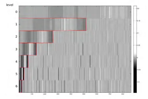
again we will only show the recorded data in Chapter VI. Instead, we focus on the synchro-nization of the grasping and the finger opening. The methods used in this work are wavelet analysis based, readers can refer to [Mallat 08] for a detailed discussion on wavelets and the comparison to Fourier analysis and its variants. The Wavelet Packet Transformation
(WPT) used for feature extraction are reported in various works, as in [Englehart 99] for myoelectric signal, and in [Learned 95] for underwater acoustic signals.
The Linear Discriminant Analysis are used to select features, a nice explanation of
which can be found in the book of Bishop [Bishop 06]. Relevance Vector Machine, used as
a classifier in this work, was firstly introduced by Tipping [Tipping 01]. Frequency infor-mation based classification, although with different feature forinfor-mation, is also reported with successful application on touch classification [Sato 12], and especially on image classifica-tion, such as in [Rehman 12].
A first design of the object intended to record human-human object exchange was re-ported in [Sidobre 09], using wavelet analysis to study the forces. The previous work gives interesting results. And in this thesis, we propose a more general solution by learning to build more universal models.
2.6
Conclusion
This chapter presented firstly the robots and the software architecture, and included the lit-erature review of the topic of this thesis and some presentation of the related works at LAAS-CNRS. This thesis has been a part of the effort to develop a human-aware, autonomous mo-bile manipulator. For this reason, the research objectives are all real problems related and cooperation related. The first consequence is that the thesis covers different areas, but all application linked together. Even if the results depend on other components of the system: the control would not be possible without a human-aware motion planner, and the fusion would not achieve any results if not for a 3D vision system. Although time consuming, cooperation and being part of big research project provided an opportunity to learn various related domains and to train the ability to work as part of a team.
Because it covers three different research topics, this document does not aim to provide an exhaustive literature review on all the topics. Nevertheless, comparisons between the chosen approach and other methods are provided. Trajectory control for visual tracking, for example, achieves similar functions as classical visual tracking. Some cited papers are review papers for the area, and provide good reading lists.
3
Force Vision Sensor Fusion
The eye sees only what the mind is prepared to comprehend.
—Henri Bergson
Abstract. The objective of this research work is to achieve a sensor-based reactive control, for which the precision and robustness of perception is an important component. In this chapter, we will discuss two problems in robot perception to improve the interactive manipulation: the force sensing to identify the unknown manipulated object, and kinematics tracking model based on vision and force fusion. For the two problems, the nonlinear Kalman filter is used as the sensor fusion method. Identifying the dynamics parameters of the manipulated object during manipulation is the main challenge for the first problem, while updating the filtering process from different sensors, mainly force and vision, is the focus for the second. The basics of nonlinear Kalman filters are included in appendix.
3.1
Introduction
Robot control in human-robot interactions is a challenging task. Simple planned position control is not adequate in this context. The nature of HRI demands the robot to be reactive during the manipulations, which means the robot should adapt its activities according to the sensory inputs, being visual, tactile, forces/torques, or depth sensors. In this thesis, we call it sensor-based reactive manipulations, which differs from pre-planned manipulations in the
way that the reactions do not need constant involvement of the planning algorithms, several important advantages can be obtained:
• Planning is often time-consuming hence not fast enough for real-time reactions.
• Reactive control based only on the proposed trajectory generator have a fixed com-puting time, while planning by RRT and similar methods have a varying computation time.
• By building models from the perception data, the manipulation control is directly improved.
In this chapter, we propose to solve two problems of sensor fusion aiming to achieve a controller for sensor-based manipulations. The work on machine learning and control will be discussed in other chapters. Firstly, we discuss the force-sensing problem. The goal of this part is to use a 6D forces/torques sensor mounted on the wrist of the robot arm to estimate the inertial parameters of the tool/load mounted on the robot. Then with the inertial parameters, the external forces/torques on the tool are computed. Secondly, we use the results of force sensing to improve the kinematics tracking by force-vision sensor fusion, including object recognition by inertial parameters, and object localization integrated into visual tracking.
On-line estimation of the inertial parameters of the manipulated object can benefit many aspects of the manipulation, as we will show in the next section. The vision/force fusion does not only improve the performance of the trajectory controller, but also help the facts assessment for the higher level software.
Multi-sensor fusion is a problem for which various methods are proposed in the liter-ature. The review and comparison of different techniques can be found in chapter II. The choice of the technique determines a different choice of the models and the formulation for the problem. For the advantage of clarity in mathematical background and software performance, Kalman Filter based methods are chosen for the two problems at hand. In the following chapters, we will model the problems as a dynamical system, suitable for Kalman filter formulations. It should be noticed that other techniques would use totally dif-ferent models. For example, when the force sensing part is solved by offline Least Squares, and the tracking part is fused by Dempster-Shafer theory, a different model is needed of the same problem.
The rest of the chapter is organized as follows. Firstly, the problem formulation for force sensing is in the Section3.2. The multimodal sensor fusion will be discussed in Section3.3. After this, we will give the algorithm of Unscented Kalman filtering in Section3.4.
3.2
Force Sensing
3.2.1 Inertial Parameters Estimation
Various applications in service and assembly robotics can benefit from the estimation of in-ertia parameters, which are the mass, the coordinates of the centre of mass, and the elements of the inertia matrix. Furthermore, complex tools are not always provided with suitable dy-namical models so that experimentally estimated inertial parameters can be more precise and more useful. By estimating the inertial model of the tool/manipulated object, the ex-ternal forces executed directly on the end effector or on the manipulated object should be available to improve the control of object exchange.
The techniques presented in this chapter are also used in the next part of this work, asso-ciated to the design of an object intended to teach the robot to synchronize the grasp-release during object exchange, as external forces/torques are needed for the learning procedure.
Fs
Fc roc
Figure 3.1: Frames for force/torque sensing
We propose a model of the relation between the dynamics of the manipulated object and the robot wrist force/torque in this section. Figure3.1shows the important frames for the problem. The hand, the force/torque sensor and possibly the acceleration sensor are all mounted on the end of the robot arm. Firstly, we chose the robot base as the inertial refer-ence coordinates system for this system. This assumption is reasonable because the robot rarely manipulates objects while doing fast navigation. The transform matrices between the sensors and the hand are fixed and measured by experiments. The one from hand to arm is
calculated through forward kinematic transformation.
wrist
Inertial Measurement Unit(IMU)
S (f/t sensor)
W (world) B(base)
W (3D vision)
task C (object)
human
Figure 3.2: The frames for force/torque sensing and vision tracking and relations between them. The dashed lines are associated to the transformation matrices.
Once the position of the manipulated object in the frame of force/torque sensor is es-timated, the position in the hand frame is obtained. We skip all the detailed terms of the matrices for the clarity of the document. To simplify the dynamic model, we also make the assumption that the frame of the object is parallel to the frame of hand. This is not a problem because in the next section, we do not try to match the exact inertia matrix but only the characteristics of the matrix are used for object recognition, and the rotation of frame will not affect the localization of the center of mass (COM). A more specific choice of the frames can be accomplished after the first estimation. And different frame rotations will not affect the position of the COM in the force sensor frame and the mass, of course, stays unchanged. The force/torque sensor measures the action and reaction force and torque between the robot arm and the end effector, in our case, a robot hand or a gripper.
Notations:
fms: Forces measured by f/t sensor, w.r.t. the sensor frame. τs
m: Torques measured by f/t sensor, w.r.t. the sensor frame. fs: Real action forces between sensor and object.
τs: Real action torques between sensor and object. fextc : Contact forces on object, w.r.t. the object frame. τextc : Contact torques on object, w.r.t. the object frame. fs
o f f : Sensor offsets on forces. τo f fs : Sensor offsets on torques.