HAL Id: hal-01847309
https://hal.archives-ouvertes.fr/hal-01847309
Submitted on 23 Jul 2018
HAL is a multi-disciplinary open access
archive for the deposit and dissemination of
sci-entific research documents, whether they are
pub-lished or not. The documents may come from
teaching and research institutions in France or
abroad, or from public or private research centers.
L’archive ouverte pluridisciplinaire HAL, est
destinée au dépôt et à la diffusion de documents
scientifiques de niveau recherche, publiés ou non,
émanant des établissements d’enseignement et de
recherche français ou étrangers, des laboratoires
publics ou privés.
Entangled cross-linked fibres for an application as core
material for sandwich structures - Part I: Experimental
investigation
Laurent Mezeix, Dominique Poquillon, Christophe Bouvet
To cite this version:
Laurent Mezeix, Dominique Poquillon, Christophe Bouvet. Entangled cross-linked fibres for an
appli-cation as core material for sandwich structures - Part I: Experimental investigation. Applied
Com-posite Materials, Springer Verlag (Germany), 2015, 23 (1), pp.71-86. �10.1007/s10443-015-9451-6�.
�hal-01847309�
O
pen
A
rchive
T
OULOUSE
A
rchive
O
uverte (
OATAO
)
OATAO is an open access repository that collects the work of Toulouse researchers and
makes it freely available over the web where possible.
This is an author-deposited version published in :
http://oatao.univ-toulouse.fr/
Eprints ID : 14146
To link to this article :
DOI: 10.1007/s10443-015-9451-6
URL :
http://dx.doi.org/10.1007/s10443-015-9451-6
To cite this version :
Mezeix, Laurent and Poquillon, Dominique
and Bouvet, Christophe (2015)
Entangled cross-linked fibres for an
application as core material for sandwich structures - Part I:
Experimental investigation
.
Applied Composite Materials. pp. 1-16. ISSN 0929-189X
Any correspondance concerning this service should be sent to the repository
administrator:
[email protected]
Entangled Cross-Linked Fibres for an Application
as Core Material for Sandwich Structures - Part I:
Experimental Investigation
L. Mezeix1,2&D. Poquillon1&C. Bouvet2
Abstract Entangled cross-linked fibres were studied for an application as core material for sandwich structures. Specimens were produced from carbon, aramid and glass fibres, and cross-links were achieved using epoxy spraying. It was observed that this type of entangled cross-linked fibres could be fabricated without any major technical difficulties. The scope of this paper is to study the effect of some different parameters on the mechanical properties of these materials. Different effects were investigated: effect of fibres length, of fibres nature, of mixing fibres, of carbon skins and of the resin. The first part of this paper deals with the production of these entangled cross-linked fibres. The compression, tension and three point bending tests are detailed in the second part and the results are compared with usual core material currently used in industries.
Keywords Entangled fibres . Porous material . Mechanical testing . Sandwich structure . Core material
1 Introduction
A sandwich panel consists of two thin skins separated by a thick core. Many different sandwich panels are used for naval, aeronautic and other applications. Open and closed cell structured foam, balsa wood or honeycomb are often used as core materials because of their low density, good crush resistance and high out-of-plane resistance. When the core material contains closed cells, water accumulation into the cell has to be taken into account. This
* C. Bouvet
1
Université de Toulouse, CIRIMAT, INPT-ENSIACET, 4 allée Emile Monso, BP 44362, 31432 Toulouse Cedex 4, France
2
phenomenon occurs when, in service, conditions lead to operate in a humid atmosphere [1]. Then, water vapours from air naturally and condenses on cold surfaces as the sandwich panel temperature decreases. This water accumulation may significantly increase the weight of the core material, induce damages and degrade the mechanical properties. Core with a ventilated structure helps to prevent this phenomenon. Periodic Cellular Metal (PCM) structures are motivated by potential multifunctional applications that exploit their open architecture as well as their apparent superior strength and stiffness e.g., pyramidal, lattice, Kagome truss or woven [1–12]. One of the drawbacks of these materials is its expensive manufacturing cost. Recently, a new type of sandwich was developed from bonded metallic fibres as core material [13–19]. Entangled materials can be made from natural materials (wool, cotton, etc.) as well as from artificial ones (steel wool, glass wool, etc.). Bonded metal entangled cross-linked fibres offer advantages [17–28] for use like heat exchanger [26], insulation [27] or noise reduction [28]. They present a relatively low density, a high porosity and a simple production process thanks to cost-effective routes, with considerable versatility concerning metal composition and network architecture. Bonded metallic fibres present attractive combination of properties like high specific stiffness, good damping capacity and energy absorption. Metal fibres are bonded with a polymeric adhesive [15,16] or fabricated in a mat-like form and consolidated by solid state sintering [20]. Entangled fibres were cross-linked by epoxy spraying under air flow to be used as core material [29–31]. Entangled cross-linked fibres present many advantages for applications as core material i.e., open porosity, multifunctional material, possibility to obtain a curved panel, possibility to have a graduated variation of thickness or possibility to reeve electric or control cables on core material. Epoxy spraying under air flow process seems promising due to its low manufacturing cost and the possibility to entangle different sort of fibres e.g., carbon, glass, steel etc. Mechanical behaviour was studied in entangled fibres and cross-linked fibres with carbon, glass and stainless steel fibres [29,30]. Shahdin et al. studied the mechanical behaviour of sandwich structures with entangled cross-linked fibres as core material for damping capabilities [31]. In these recent works, tests demonstrated the presence of high damping in the entangled sandwich specimens making them suitable for specific applications like the inner panelling of a helicopter cabin [32], even if the structural strength of this material was found to be on the lower side.
In the presented work, carbon, aramid and glass fibres were chosen. The purpose is to study the mechanical behaviour of sandwich with core materials made from entangled cross-linked fibres. In the first part, the fabrication was fully exploited. In the second part, the mechanical behaviour of the sandwich with different entangled cross-linked fibres as core was investigated under compression, tension and three-points bending. Then, the mechanical properties are compared with the ones of the honeycomb and foam core.
2 Materials and Methods
2.1 Material Fabrication
Carbon fibres (200 Tex) made of yarns of stranded carbon filaments are provided by Toho Tenax. The filament diameter is 7μm and the elastic modulus is 240 GPa. Glass fibres (600 Tex) are obtained from yarns that are provided by PPG glass fibres. The filament diameter is 12μm with an elastic modulus is 73 GPa. Aramid fibres have a diameter of 12.5 μm for a Young modulus of 36 GPa in compression and 120 GPa in tension. They are supplied by
Imattec. For aeronautical applications, many sandwich panel skins are made using carbon/ epoxy prepreg. That is the reason why epoxy resin was chosen for fibres cross-linking. Two different epoxy resins (reference SR8100 and SR1710) were chosen for their low viscosity, (285 and 130 mPa.s respectively). They are supplied by SICOMIN. Their Young moduli in tension are 2.4 GPa for SR8100 and 3.4 GPa for SR1710. For all the tests carried out during this work, specimens are carefully weighted using METT LERS balance (±0.1 g). A spray paint gun (FIAC UK air compressors) is used for spraying epoxy. Materials were observed using a Scanning Electron Microscope (LEO435VP) operating at 15 kV.
The first step of the elaboration is the separation of filaments from received yarns. As the relative density of the material needs to be as low as possible, a previous study showed that the yarns size needs to be decreased by separating filaments [29]. The entangled cross-linked fibres are obtained following the process detailed elsewhere [30]. For all materials elaborated in the present study, the fibres are cut with a fibre cutting machine provided by MATRASUR Composite. Separation of carbon yarns is performed in a blower room. The air fluxes and pressure (5 bars) of this blower room are sufficient to separate the filaments. Entanglement is also obtained using a controlled air flow in this specific blower room and epoxy is sprayed using paint spray gun during the last minutes of the entanglement. The fibres density of the sample tested in this study is 150 kg/m3 and the epoxy quantity applied by vaporization is about 30 kg/m3. As the volume of the mould is known and the fibres mass is carefully weighted, the volumetric density is controlled. Finally the material made of entangled cross-linked fibres is introduced in specific mould and is polymerized at 60 °C for 8 h in a furnace in laboratory conditions. Materials elaborated with mixed fibres can be manufactured by this method. In this work, carbon and glass fibres are mixed. Figures1,2and3show typical SEM observations of entangled cross-linked carbon, aramid and glass fibres respectively. We can clearly observe the epoxy joints between filaments. Some tiny yarns remain but they are only fibres compared with the initial yarns. Glass fibres seem to be less separated than the carbon or the aramid fibres.
Fig. 1 Typical SEM observation of carbon entangled cross-linked fibres. Fibres density is 150+30 kg/m3of epoxy resin
2.2 Compression and Tension Tests
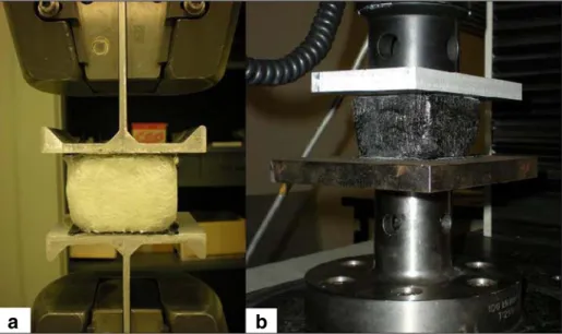
The quasi-static out-of-plane compressive and tension response of sandwich samples are measured in a screw-driven Instron machine with a 10 kN load cell. The sample size is 60× 60×40 mm3 in compression and in tension. The specimens are compressed between two square plates. For tension tests, samples were glued with Araldite 2015 epoxy adhesive to the punches and introduced in the cross bar (Fig.4). Similar entangled cross-linked fibres were studied for an application of core material, tests were performed with skins (sandwich sample) and without skins (entangled cross-linked fibres sample). For the compression and tension tests, the material skins always consist of two carbon layer of woven for a total thickness of
Fig. 2 Typical SEM observation of aramid fibres entangled cross-linked fibres. Fibres density is 150+30 kg/m3 of epoxy resin
Fig. 3 Typical SEM observation of glass fibres entangled cross-linked fibres. Fibres density is 150+30 kg/m3of epoxy resin
1.2 mm. The punch velocity has a constant rate of v0=5 mm.min−1corresponding to an initial
nominal strain rate of˙ε ¼ 2:10−3s−1. To analyse the experimental results, the standard defini-tions for the engineering strain and stress are used. On the stress range tested there is no significant modification of the surface area, so S0≈ S. The initial stiffness of the materials is
measured during partial unloading. 2.3 Three-Point-Bending Tests
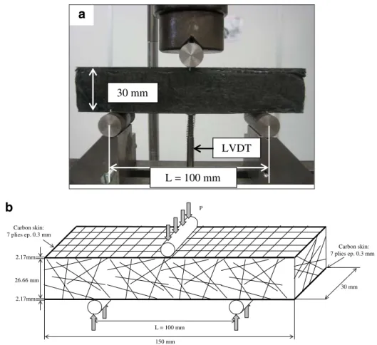
Three-point-bending tests are carried out to measure the out-of-plane shear modulus of the bending test specimens on a 10 kN Instron machine. As discussed previously, these specimens have a 150 kg/m3fibres core density. The sample size is 150×31×30 mm3with 2.1 mm of carbon layer of woven as skins (HEXPLY® M21/40%/46280/1200). Skins are bonded with a Redux® film Adhesive (Hexcel Redux 609) under vacuum (1 bar). The distance between the two lowest spans is 100 mm (Fig.5a) and the applied velocity is vo=2 mm.min−1. Round steel
bars or pipes are used as supports having a diameter of 15 mm which is not less than one half the core thicknesses and not greater than 1.5 times the sandwich thickness as per ASTM standards [33].
The load, P, is applied at the centre of the beam. The maximum deflection,δ, of the beam results both from flexural and shears deformations (Eq. (1)). Deflection is measured by a LVDT sensor. Indentation is obtained by the difference between the cross displacement and the deflection. The shear deformation is predominant in the core; so the elastic deflection can be approximately expressed as follows:
δ ¼ PL3 48Aþ
PL
4B ð1Þ
a
b
Fig. 4 Sandwich with (a) glass entangled cross-linked fibres as core under tension load and (b) carbon entangled cross-linked fibres as core under compression load
with A¼Estsh
2b
2 and B¼ bhGc ð2Þ where
P is the applied load
L is the distance between lower spans (100 mm) ts is the thickness of the skin (2.17 mm)
tc the thickness of the core (26.66 mm)
h = tc+ tf(28.83 mm) and b is the width of the beam (30 mm) (Fig.5b)
Es is the elastic modulus of the carbon skins
in the axial direction (60 GPa) Gc is the shear modulus of the core
The maximum deflection is calculated experimentally by the three-point bending test, the only unknown value is the shear modulus Gcwhich is calculated by putting Eq. (2) in Eq. (1).
The obtained equation is only valid for the beginning of the bending tests when the deflection is relatively small and is used only to evaluate the shear modulus.
L = 100 mm LVDT 30 mm
a
60 mm 26.66 mm 150 mm 30 mm Carbon skin: 7 plies ep. 0.3 mm Carbon skin: 7 plies ep. 0.3 mm 2.17mm 2.17mm L = 100 mm Pb
3 Results and Discussions
3.1 Out-of-Plane Compression
3.1.1 Effect of Fibres Nature and Skins Effect
Figure 6shows results of compression tests for glass, aramid and carbon entangled cross-linked fibres. The length of fibres is 45 mm and the fibres density is 150 kg/m3for each type of fibres. The carbon sample presents a higher stiffness as compared to the material made with other fibres (same fibres density). The rigidity of a beam under bending loading depends on the bending stiffness and on the cubic of the beam length, which in our case is the distance between two epoxy joints. In this work, the bending stiffness of glass fibres (EI=7.4× 10⁻⁵N.mm2) is higher than the one made of aramid (EI=4.3×10⁻⁵N.mm2) and carbon fibres (EI=2.8×10⁻⁵N.mm2). But as the initial fibre density is the same in this work, the relative volumetric density of the material made with aramid fibres (10.7 %) is larger than with carbon (8.5 %) and glass (5.9 %). As the average distance between fibres contacts, Lcontact, is related to
the fibres diameter, D, and the volume fraction of the fibres, f, we can determine the theoretical distance (See Eq. (3)) [34–36]:
Lcontact¼
D
2 f ð3Þ
Due to the parameters of our samples, the theoretical distance between fibres contact is shorter for the carbon (41μm) than for the aramid (58 μm) and for the glass fibres (100 μm) (Eq. (3)). To confirm this point, many SEM observations were carried out (Figs.1,2and3)
-3,5 -3,0 -2,5 -2,0 -1,5 -1,0 -0,5 0,0 -90% -80% -70% -60% -50% -40% -30% -20% -10% 0%
Sandwich with carbon fibres as core Carbon fibres network
Sandwich with glass fibres as core Glass fibres network
Aramid fibres network
Strain
Stress [MPa]
ρfibre = 150 kg/m3
ρresin = 30 kg/m3
ρtotal = 180 kg/m3
Fig. 6 Stress-true strain curves of carbon and glass entangled cross-linked fibres and sandwiches with these entangled cross-linked fibres as core
and the distances between junctions were measured. The observed average distance is smaller for carbon fibres (120μm− 70μm+ 140μm) than for aramid (180μm− 120μm+ 190μm) and glass (200μm− 115μm+ 215μm).
The distances measured are higher than those predicted. Firstly, due to our process: each fibres contact is not bonded by the epoxy, secondly, this theoretical value is applicable for a 3D network of infinitely rigid fibres, which is not the case in our study. Furthermore, the measure of the distance between junctions achieved using SEM observations may induce approxima-tion. So the rigidity of the microscopic beam between contacts is the largest for carbon fibres. This can be the reason why the initial stiffness measured during unloading of carbon sample (5 ± 0.5 MPa) is larger than the one obtained with the aramid fibres (3.1 MPa) and the glass fibres (1.7 MPa). So, it can be seen that the distance between epoxy cross-links is one of the most important parameters to relate to the stiffness. To have a better knowledge of the core architecture, more characterisations of morphol-ogy, like tomography observations, will need to be carried out.
As a sandwich consists of two skins separated by a core, the effect of skins in entangled cross-linked fibres is interesting because entangled cross-linked fibres will be studied as core material for sandwich structures. Figure6shows the effect of the skins on sandwich samples with carbon and glass entangled cross-linked fibre cores studied above. The effect of the skins is not tested with the entangled cross-linked aramid fibres. For the same fibres length (45 mm), the same fibres density (150 kg/m3) and the same quantity of resin (30 kg/m3), the stiffness of sandwich with entangled cross-linked fibres as core is similar with the entangled cross-linked fibres (without skins). In consequence, the modification of the boundary conditions of the entangled cross-linked fibres due to the addition of the skins does not seem to affect its stiffness. Sandwiches with different length of fibres are considered in the next paragraph to study the effect of these boundary conditions.
3.1.2 Effect of Fibres Length
Sandwiches with entangled cross-linked carbon fibres as core material are tested with different lengths of fibres to study the effect of boundary conditions (Fig. 7). Three different fibres lengths are used: 22, 31 and 45 mm for a core material height of 38.2 mm. Whatever the fibre length used, samples do not present significant difference of initial stiffness. So, for this range of length of fibres, the stiffness of the entangled cross-linked fibres is mainly related by the distance between epoxy joints as described previously. Distances between epoxy joints have been measured by SEM observations and seem to be similar i.e., 125μm− 80μm+ 190μm, 135μm− 125μm+ 205μm,
and 120μm− 70μm+ 140μm, for a respective length of fibre of 22, 31 and 45 mm. As we previously
observed, one of the main parameter to relate to the stiffness is the distance between junctions. As the length of fibres is much larger than the distance between junctions (about 100 times higher in our case), the length of fibres will not have an influence on the stiffness of the entangled cross-linked fibres. Conversely, if the length is very short, the entanglement of the fibres could affect the stiffness. To confirm this behaviour, boundary conditions need to be studied for very short and very long fibres. Fibres shorter than 10 mm were not studied due to the limitation of the manufacturing process.
3.1.3 Effect of Mixing
An interesting feature of entangled cross-linked fibres as core material is the possibility to mix different types of fibres. To study this property, carbon and glass fibres are mixed. Samples
with different weight ratios of carbon fibres were manufactured. The total fibres density (carbon + glass fibres) is always 150 kg/m3and the quantity of resin is 30 kg/m3. So the relative volumetric density of fibres of the tested materials differs. For the same strain, the stress decreases by increasing the quantity of glass fibres mainly due to a decreasing fibre volume fraction (Fig.8).
-3.5 -3.0 -2.5 -2.0 -1.5 -1.0 -0.5 0.0 -70% -60% -50% -40% -30% -20% -10% 0% Strain Stress [MPa] ρfibre = 150 kg/m3 ρresin = 30 kg/m3 ρtotal = 180 kg/m3 38,8mm Fibres network Carbon skins Lfibre = 45 mm Lfibre = 31 mm Lfibre = 22 mm
Fig. 7 Stress-true strain curves of sandwiches with different lengths of carbon entangled cross-linked fibres as core -3,0 -2,5 -2,0 -1,5 -1,0 -0,5 0,0 -90% -80% -70% -60% -50% -40% -30% -20% -10% 0% Strain Stress [MPa]
100% carbon fibres network, ftotal = 8.5%
81% carbon fibres network, ftotal = 8.0%
59% carbon fibres network, ftotal = 7.3%
32% carbon fibres network, ftotal = 6.6%
100% glass fibres network, ftotal = 5.9%
ρfibre = 150 kg/m3 ρresin = 30 kg/m3 ρtotal = 180 kg/m3 Volume quantity Fibres network f
Figure9shows the evolution of Young modulus of different mixed entangled cross-linked fibres. This Young modulus is measured during the unloading. We can observe that the rigidity of materials elaborated with mixed fibres is relatively constant and always between the rigidity of the 100 % carbon material and the 100 % glass samples. Whatever the quantity of mixed fibres, cross-links between fibres were observed by SEM observations (Fig.10). As the fibres density and epoxy quantity are constant, the volume fraction increases with the quantity of carbon, so the distance between joints, L, decreases (Fig.9). As one of the parameter related to stiffness is the bending of microscopic beams, the stiffness should increase with the quantity of carbon. Other types of fibres need to be mixed to obtain the effect of each parameter (f, EI, L and D) in order to have a better knowledge of the overall behaviour. Different experiments could be carried out e.g., mixing two types of fibres with the same bending stiffness to study the effect of the distance between junctions or fibres with the same diameter could also be mixed to work at constant volume fraction, unfortunately we could not manage to source such fibres.
3.1.4 Effect of Epoxy Resin
To study the influence of the resin in the stiffness of the entangled cross-linked fibres, two different resins (reference: SR1710 and SR8100) were used. The rigidity and the viscosity of the resins are different (Fig.11).
As the quantity of fibres and resin are the same, densification behaviour of the two samples is similar (Fig.11). Although the stiffness of SR8100 resin is smaller than that of SR1710 resin, the Young moduli of the core materials are similar (5 MPa). Firstly, epoxy joints are observed using SEM to check if the type of resin has an influence on their geometry. The size and the geometry of the joints seem to be similar for the two resins (Fig.12). Secondly, the distance between the joints are measured and compared for the two samples. The distance
0.0 0.5 1.0 1.5 2.0 2.5 3.0 3.5 4.0 4.5 5.0 0% 20% 40% 60% 80% 100% 0% 1% 2% 3% 4% 5% 6% 7% 8% 9%
Volume quantity of carbon
Young modulus [MPa]
Young modulus Total volume fraction
Volume fraction L = 200 µm L = 183 µm L = 139 µm L = 162 µm L = 120 µm
Fig. 9 Evolution of volume fraction and stiffness of mixed entangled cross-linked fibres in function of carbon fibres volume quantity
between the joints is smaller for the weakest resin (SR8100,L=100μm− 80μm+ 160μm) than for the second (SR1710,L=120μm− 70μm+ 140μm). The entangled cross-linked fibres stiffness is probably identical because the epoxy joints have a lower stiffness with the weakest resin, but the distance between the joints is shorter. In conclusion, the effect of the resin is difficult to analyse because two parameters are changed simultaneously. Therefore other types of resin could be used to obtain a better knowledge of the material behaviour e.g., thermoplastic resin
Junction glass/glass
Junction glass/carbon
Junction carbon/carbon
Fig. 10 Typical SEM observation of mixed entangled cross-linked fibres. Fibres density is 150+30 kg/m3of epoxy resin -3.5 -3.0 -2.5 -2.0 -1.5 -1.0 -0.5 0.0 -80% -70% -60% -50% -40% -30% -20% -10% 0% Strain Stress [MPa] ESR8100 = 2.4 GPa (285 mPa.s) ESR1710 = 3.4 GPa (130 mPa.s)
Carbon network, resin SR1710 Carbon network, resin SR8100
ρfibre = 150 kg/m3
ρresin = 30 kg/m3
ρtotal = 180 kg/m3
Fibres network
could be used to create a great variation of the rigidity of the junction, but the vaporization of such resin is difficult with our process.
3.2 Tension Tests
Tension tests are also carried out first to determine the behaviour of entangled cross-linked fibres under tensile load and second to compare the stiffness with the modulus measured in compression. Figure13compares results of tension tests for entangled cross-linked carbon, aramid and glass fibres. Fibres length is 45 mm and the density is still 150 kg/m3. The curve indicates the elastic domain (1), the distinct peak stress (2) followed by material degradation (broken epoxy junctions and then sliding of the fibres) (3). Young modulus in tension is 17.5± 4.5 MPa for the carbon, 4.4 MPa for the glass and 6.5 MPa for the aramid fibres. So Young
a
b
Fig. 12 Typical SEM observation of carbon entangled cross-linked fibres bonded by the epoxy resin reference (a) SR1710 and (b) SR8100 0.00 0.05 0.10 0.15 0.20 0% 10% 20% 30% 40% 50% 60% 70% 80% 90% 100%
Carbon fibres network Glass fibres network Aramid fibres network
Strain Stress [MPa] ρfibre = 150 kg/m3 ρresin = 30 kg/m3 ρtotal = 180 kg/m3 (1) (2) (4) Fibres network (3)
modulus measured in tension is higher than Young modulus measured during compression tests, 5±0.5 MPa for the carbon and 1.7 and 3.1 MPa respectively for the glass and the aramid fibres. The increase of the stiffness is probably due to additional stiffness of the vertical fibres. When under tension, these vertical fibres can support loading whereas they buckle quickly under compression. Core material degradation is faster for the carbon and glass fibres than for the aramid fibres (4). It is difficult to find a pertinent reason for this behaviour due to the large number of parameters involved, but the main parameter is probably the behaviour of the fibres. One of the reasons of the low resistance in tension of carbon fibres could be its lowest tensile elongation (1.8 %) in comparison with glass (4 %) and aramid fibres (2.8 %). It is possible that epoxy junctions adhesion could also be involved. The difference of the volume fraction of the fibres could also explain the higher resistance of the aramid fibres.
3.3 Three-Point-Bending Tests
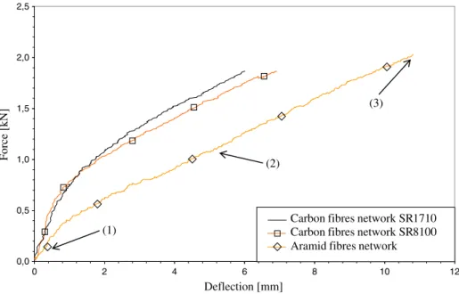
Figure 14reports load-deflection curves of three-point-bending tests on sandwich samples with entangled cross-linked fibres as core material. The aim of the bending tests in this work is only to determine the out-of-plane shear modulus Gcof the core material. Only two types of
entangled cross-linked fibres are tested: aramid and carbon fibres. Entangled cross-linked glass fibres are not studied because their stiffness is too low to be elaborated under vacuum (1 bar). Aramid fibres are bonded only by the SR1710 resin as in the case of compression tests and their effect on the resin is only studied with the carbon fibres.
The initial linear-elastic behaviour (1) is followed by a non-linear phase (2) until the debonding of skin (3) (Fig.14). The aramid fibres present the highest deflection, although it is similar for the two different carbon fibres core. The out-of-plane shear modulus Gc is
obtained by Eq. (3). The moduli for the two entangled cross-linked carbons fibres are 30 MPa,
0,0 0,5 1,0 1,5 2,0 2,5 0 2 4 6 8 10 12 Deflection [mm] Force [kN] (1) (2) (3)
Carbon fibres network SR1710 Carbon fibres network SR8100 Aramid fibres network
Fig. 14 Load-deflection curves during three-point-bending tests for sandwich with different entangled-cross linked fibres as core material
whereas for the aramid fibres the modulus is only 14 MPa. As in the case of compression tests, the stiffness is higher for the carbon fibres and the modification of the resin does not seem to have a significant effect on their behaviour.
4 Discussion and Conclusion
In this study, we elaborated a new core material that consists of entangled cross-linked fibres. Many different core materials are currently used for aeronautical applications, honeycombs and foams being the ones mostly used. It is interesting to compare carbon entangled cross-linked fibres with different core materials. We chose two different cores materials currently used in industries i.e., Nomex honeycomb [37] and ROHACELL foam [38] (Table1).
The rigidity of entangled cross-linked fibres in compression and in shear is lower than that for other core materials. So, for a structural application, carbon entangled cross-linked fibres as core material do not present any advantages in comparison with honeycombs or foams. But for many applications, rigidity is not the main parameter. An open porosity to evacuate fluid, good damping properties, multifunctional properties, possibility to obtain complex shapes or the possibility to reeve electric or control cables into the core material are some examples of the other properties required. For these types of applications, entangled cross-linked fibres present an interesting prospect. Manufacturing simplicity and good formability are also one of the major advantages of this type of material. So, entangled cross-linked fibres can present an interest as core material for various applications without excellent structural properties.
As a conclusion, three different families of core materials made of carbon, aramid and glass entangled cross-linked fibres were tested. Out-of-plane compression, tension and three-points bending tests were carried out to study the mechanical behaviour of these materials. Different parameters were investigated such as: the effect of fibres length, the effect of carbon skins and also the effect of mixing fibres and the effect of resin. According to the experiments, the mechanical behaviour of the sandwich panels can be concluded as follows:
& Entangled cross-linked carbon fibres present a higher stiffness than glass and aramid fibres for the same fibre density. Distance between junctions is found to be the main parameter related to the stiffness. As the entangled cross-linked fibres have been fabricated at constant density, the distance between junctions is not the same due to the difference in volume fraction of fibres and fibre diameters. From SEM observations, distances are measured: they are shorter for the carbon and longer in the case of glass fibres.
Table 1 Comparison of mechanical properties of different core materials Nomex honeycomb HRH-10-3/16-4.0 [37] ROHACELL 51HF [38] Carbon entangled cross-linked fibres ρ [kg/m3] 48 52 180 Ecompression[MPa] 137 70 5 Ecompression/ρ [MPa.m3/kg] 2.85 1.34 0.03 Etension[MPa] – – 17.5 Gc[MPa] 45 19 30 Gc/ρ [MPa.m3/kg] 0.94 0.36 0.17
& The modification of the boundary conditions of the entangled cross-linked fibres due to the addition of the skins does not seem to change their stiffness. Regarding the fibres length studied which are a hundred times greater than the distance between junctions, the rigidity of the entangled cross-linked fibres depends mainly on the quantity of fibres and the distance between junctions.
& Due to the process used in this work, it is possible to obtain a multifunctional material by mixing different types of fibres. Carbon and glass fibres are mixed and the epoxy bonding is successfully achieved between the fibres. Whatever the quantity of carbon mixed with glass fibres, the initial stiffness under compression load seems to be the same.
& To study the effect of the resin on the stiffness of the entangled cross-linked fibres, carbon fibres were bonded by two different resins. In case of compression tests, no difference is noted between the two samples. The junctions seem to have the same size and geometry. On one hand, the stiffness of the epoxy joints is smaller with the weakest resin, but on the other hand, the distance between joints is smaller for the sample made with this resin. & Young moduli measured in tension are higher than those measured under compression
probably due to the additional stiffness of the vertical fibres. When under tension these vertical fibres support loading whereas they buckle quickly under compression. Due to the behaviour of the fibres, entangled cross-linked aramid fibres presents a better resistance than the other two materials.
& Shear modulus is measured from three point bending tests. As in compression, the stiffness is the highest in case of carbon fibres. These samples bonded by the two resins used in compression present also the same behaviour.
To obtain a better knowledge of entangled cross-linked fibres and in order to optimize their properties, a number of experiments have to be carried out to complete this study resulting in a better overall comprehension. We could focus on the adhesion of the epoxy and on the quantity of junctions achieved. Furthermore, thermoplastic resin could be vaporized on the fibres to enhance the study concerning the effect of resin, especially for a future application of impact resistance. Finally, other types of fibres need to be mixed to obtain a better knowledge of the behaviour e.g., fibres with the same diameter or the same bending stiffness could be used. Finally, numerical modelling will be carried out to supplement the understanding of the behaviour.
References
1. Queheillalt, D.T., Wadley, H.N.G.: Pyramidal lattice truss structures with hollow trusses. Mater. Sci. & Eng. A. 397, 132–137 (2005)
2. Queheillalt, D.T., Murty, Y., Wadley, H.N.G.: Mechanical properties of an extruded pyramidal lattice truss sandwich structure. Scripta Mater. 58, 76–79 (2008)
3. Kooistra, G.W., Queheillalt, D.T., Wadley, H.N.G.: Shear behavior of aluminium lattice truss sandwich panel structures. Mater. Sci. and Eng. A. 472, 242–250 (2007)
4. Wallach, J., Gibson, L.J.: Mechanical behavior of a three-dimensional truss material. Int. J. of Solids and Struct. 38, 7181–7196 (2001)
5. Coté, F., Deshpande, V.S., Fleck, N.A., Evans, A.G.: The compressive and shear responses of corrugated and diamond lattice materials. Int. J. of Solids and Struct. 43, 6220–6242 (2006)
6. Lee, Y.H., Lee, B.K., Jeon, I., Kang, K.J.: Wire-woven bulk Kagome truss cores. Acta Mater. 55, 6084–6094 (2007)
7. Lee, B.K., Kang, K.J.: High Strength-per-Weight Cellular Metals Fabricated of Wires. Adv. Eng. Mater. 10, 835–839 (2008)
8. Lee, B.K., Kang, K.J.: Compressive strength of tube-woven Kagome truss cores. Scripta Mater. 60, 391–394 (2008)
9. Fang, H.L., et al.: Design and manufacture of a composite lattice structure reinforced by continuous carbon fibres. Tsinghua Science and Technology. 11, 515–522 (2006)
10. Fan, H.L., Meng, F.H., Yang, W.: Mechanical behaviour and bending effects of carbon fiber reinforced lattice materials. Arch. Appl. Mech. 7, 635–647 (2006)
11. Fan, H.L., et al.: Sandwich panels with Kagome lattice cores reinforced by carbon fibres. Compos. Struct. 81, 533–539 (2007)
12. Fan, H.L., Jin, F.N., Fang, D.N.: Nonlinear mechanical properties of lattice truss materials. Mater. Design. 30, 511–517 (2009)
13. Markaki A.E., Clyne T.W.: US Patent 10/000117, Cambridge University. (2001)
14. Markaki, A.E., Clyne, T.W.: Mechanics of thin ultra-light stainless steel sandwich sheet material: Part I. Stiffness. Acta Mater. 51, 1341–1350 (2003)
15. Markaki, A.E., Clyne, T.W.: Mechanics of thin ultra-light stainless steel sandwich sheet material: Part II. Resistance to delamination. Acta Mater. 51, 1351–1375 (2003)
16. Markaki, A.E., Clyne, T.W.: Magneto-mechanical actuation of bonded ferromagnetic fibre arrays. Acta Mater. 53, 877–889 (2005)
17. Dean J., et al.: Energy Absorption During Projectile Perforation of Lightweight Sandwich Panels with Metallic Fibre Cores. International Conference of Sandwich Structure 8th (ICSS8), Porto, 6–8 May (2008) 18. Zhou, D., Stronge, W.J.: Mechanical properties of fibrous core sandwich panels. Int. J. of Mech. Sci. 47,
775–798 (2005)
19. Masse, J.P., Bréchet, Y., Salvo, L., Bouaziz, O.: Mechanical behavior of non sintered and sintered steel wood. Material Research Society, Hong Kong (2008)
20. Gustavsson R.: WO Patent 98/01295, AB Volvo. (1998)
21. Ducheyne, P., Aernoudt, E., Meester, P.: The mechanical behaviour of porous austenitic stainless steel fibre. J. of Mater. Sci. 13, 2650–2658 (1978)
22. Clyne, T.W., Mason, J.F.: The squeeze infiltration process for fabrication of metal matrix composites. Metall. and Mater. Trans. 18A, 1519–1530 (1987)
23. Delannay, F., Clyne, T.W.: Elastic properties of cellular metals processed by sintering mats of fibres, pp. 14– 16. MetFoam’99 Conference, Bremen (1999)
24. Yamada, Y., Wen, C.E., Chino, Y., Shimojima, K., Hosokawa, H., Mabuchi, M.: Processing and mechanical properties of open-cell Mg alloys. Mat. Sci. Forum. 419, 1013–1018 (2003)
25. Markaki, A.E., Gergely, V., Cockburn, A., Clyne, T.W.: Production of a Highly Porous Material by Liquid Phase Sintering of Short Ferritic Stainless Steel Fibres and a Preliminary Study of its Mechanical Behaviour. Comp. Sci. Technol. 63, 2345–2351 (2003)
26. Golosnoy, I.O., Cockburn, A., Clyne, T.W.: Optimisation of metallic fibre network materials for compact heat exchangers. 2008. Adv. Eng. Mater. 10, 210–218 (2008)
27. Zhang, B.M., Zhao, S.Y., He, X.D.: Experimental and theoretical studies on high-temperature thermal properties of fibrous insulation. J. Quant. Spectrosc. Ra. 109, 1309–1324 (2008)
28. Paun, F., Gasser, S., Leylekian, L.: Design of materials for noise reduction in aircraft engines. Aerosp. Sci. Technol. 7, 63–72 (2003)
29. Mezeix L., Bouvet C., Castanié B., Poquillon D.: A New Sandwich Structured Composite with Entangled Carbon Fibers as Core Material. In: International Conference of Sandwich Structure 8th, Porto, May 6–8 May (2008)
30. Mezeix, L., Bouvet, C., Poquillon, P.: Mechanical behaviour of entangled fibers and entangled cross-linked fibers during compression. J. of Mater. Sci. 44, 3652–3661 (2009)
31. Shahdin, A., Mezeix, L., Bouvet, C., Morlier, J., Gourinat, Y.: Fabrication and mechanical testing of glass fiber entangled sandwich beams: A comparison with honeycomb and foam sandwich beams. Compos. Struct. 90, 404–412 (2009)
32. Piollet E., Michon G., Poquillon D.: Nonlinear Vibration Behavior of Sandwich Beams with Entangled Fiber Core Material, ASME 2013 International Design Engineering Technical Conference, Portland, Oregon, USA, doi:10.1115/DETC2013-13010
33. ASTM C 393–62.: Standard test method for flexural properties of flat sandwich constructions. (1998) 34. Toll, S.: Packing mechanics of fiber reinforcements. Polym. Eng. and Sci. 38, 1337–1350 (1998) 35. Dodson, C.T.J.: Fibre crowding, fiber contacts and fiber flocculation. Tappi J. 79, 211–216 (1996) 36. Phillipse, A.P.: The random contact equation and its implications for (colloidal) rods in packings,
suspen-sions, and anisotropic powders. Langmuir. 12, 1127–1133 (1996) 37.http://www.hexcel.com, (2015)


![Fig. 7 Stress-true strain curves of sandwiches with different lengths of carbon entangled cross-linked fibres as core -3,0 -2,5 -2,0 -1,5 -1,0 -0,5 0,0 0% -10% -20% -30% -40% -50% -60% -70% -80% -90% StrainStress [MPa]](https://thumb-eu.123doks.com/thumbv2/123doknet/12240731.319173/11.659.71.586.79.386/stress-strain-curves-sandwiches-different-lengths-entangled-strainstress.webp)