an author's https://oatao.univ-toulouse.fr/23795
https://doi.org/10.1109/JRFID.2019.2912532
Diet, Antoine and Grzeskowiak, Marjorie and Biancheri-Astier, Marc and Le Bihan, Yann and Labouré, Eric and Bouklachi, Madjda and Lissorgues, Gaëlle Flexible serialized complementary coils for the detection of moving LF RFID tags. (2019) IEEE Journal of Radio Frequency Identification. 1. ISSN 2469-7281
Flexible serialized complementary coils for the
detection of moving LF RFID tags
Antoine Diet1, Marjorie Grzeskowiak2, Marc Biancheri-Astier1, Yann Le Bihan1, Eric Labouré1,
Madjda Bouklachi1, Gaëlle Lissorgues2
1 GeePs , CNRS, CentraleSupélec, Univ. Paris-Sud, Université Paris-Saclay, Sorbonne Université, 3 & 11 rue Joliot-Curie, Plateau de Moulon 91192 Gif-sur-Yvette Cedex, France
2 ESYCOM FRE2028 (UPEMLV, ESIEE-Paris, CNAM) Cité Descartes, 93162 Noisy le Grand / 77454 MLV, France
Abstract:
This paper focuses on bats detection, tagged at low frequency (134.2 kHz) with glasstags (typically : length 15 mm and radius 1 mm). The physical link is magnetic coupling. We propose the design of a reader antenna based on a multi-coil structure.
The goal is to obtain the highest surface of detection, at a distance of 10-15 cm, i.e. defining a so called “volume of detection”. The cylindrical volume of the glasstags involves a high sensitivity to the magnetic field orientation. As the bats are flying, the tags equivalent surfaces are considered with a random orientation. Using complementary coils principle enables to detect fruitfully the glasstags in two perpendicular orientations named HM (horizontal mode) and VM (vertical mode). We propose the design of a flexible reader antenna structure by means of an adhesive copper tape fixed on a cloth. The prototype is designed after CST simulations and empirical formula evaluations. Measurements show a good agreement with the modelling and tests of detection are performed with the proposed reader antenna. By comparison with a commercial antenna, the prototype reaches the highest volume of detection in both HM and VM modes and fulfills the targeted distance of detection.
Index Terms — LF RFID, Magnetic Coupling, moving Tag.
I. INTRODUCTION AND DESIGN GOALS
Radio Frequency IDentification (RFID) is a wide and well-known concept in which the physical RF link, between a defined reader and a tag, depends on the application [1][2]. Several domains use the RFID technology for identification in access control, payment, travel cards, logistic tracking (tags) and/or location of objects, animals or persons [1]-[7]. This non-exhaustive list of cases reveals some major characteristics to focus on:
- Range of the detection
- Data rate transfer (speed of the detection) - Size of the tag (ergonomics of use) - Definition of the detection area/volume - Electromagnetic sensitivity to the environment - Movement/orientation of the tag (can be random) In near field magnetic coupling, the RFID system relies on the reader and the tag coils mutual impedance. At such frequencies (13.56 MHz or 125/134 kHz), the influence of water, biological tissues and nonmagnetic metals might disturb the magnetic coupling if the corresponding skin depth value is in the range of the layers dimensions. Range and area/volume of detection depends on the reader coil magnetic field distribution. Modifying the reader coil geometry can
improve the tags detection ability of the system, whatever theirs orientation and movement [5-10] .
In this paper, we consider a RFID system for outdoor tracking of bats in Europe. Bats belong to endangered species, and are subject to international and national protection actions, especially in France [8] since they play a catalytic part in pollination and help insect population regulation [8]. They are highly sensitive to their environment quality, and are consequently an indicator of ecologic degradation. Typically, we consider French bat species whose weight is around 5 g for a length of 5/6 cm and a wingspan of 19 to 23 cm. Bats are moving quickly and can be flying up to 20 m/s with unpredictable orientation at first glance. To perform a tagged population survey, a detection area/volume by means of the RFID reader coil can be placed on the ground, or, around or in the vicinity of a cave entrance, where bats are typically resting [8]. A realistic distance of detection in the range of 10 to 15 cm is targeted. The covered surface can be about several squared meters. As already mentioned, the presence of water and the body of the animals is supposed to be almost neglectible at this frequency since the skin depths are 32 cm and 72 cm for sea water (conductivity: 5 S/m) and body tissues (conductivity: 1 S/m), respectively. The most challenging part is to reach this range of detection over the whole surface covered by the cave entrance, i.e. covered by our prototype. Additionally, the most interesting goal for the bats tracking is to provide a detection ability almost constant over the whole surface, at a given distance of the reader coil.
The choice of the 134.2 kHz LF magnetic coupling RFID technology is mainly motivated by the mandatory reduction in size and weight of the tags, leading to use glasstags in a size range of about 1 cm, as can be seen in Figure 1 (left). These glasstags are widely used since many years for animals tracking, firstly as implanted tags [2]-[6]. Their weight is typically no more than 100 mg such as for the ID100 from
Biomarks for example [3][4][5]. Glasstags are robust,
however, they are also very sensitive to the magnetic field orientation because they are made of a cylindrical solenoid coil wounded around a ferrite rod, and connected to a RFID die. The equivalent surface of detection corresponds to the cylindrical basis of this solenoid coil. This surface is to be multiplied by the number of coil turns when calculating the magnetic flux induced. As seen in Figure 1, this equivalent surface can be oriented for being parallel or perpendicular to the reader coil structure area. The orthonormal basis (O, X, Y, Z) will be used later for evaluating the mutual inductance between reader and tag coils by simulations. Any random orientation of a tag can be considered as a weighted
2
combination of these two basics aforementioned orientations.The physical link in LF RFID is the magnetic coupling between the reader coil (coil n°1) and the tag coil (coil n°2). This phenomenon is quantified by the mutual inductance, M12=M21=M (reciprocity), and can be evaluated by the
Neumann formula, given in (1) where Ψ1 and Ψ2 are the
current paths described by the two coils n°1 and n°2, and r12
is the distance between each elementary displacement dl1 and
dl2. M is depending on the geometries of the coils, theirs
positions and orientations [1][2].
(1)
Figure 1 : Glasstag (coil 2) and its equivalent surface (left). Equivalent surface whose center is the origin O of the basis (O, X, Y, Z) (right).
RFID detection of glasstags inserted in moving bats leads to a specific case study about magnetic coupling phenomenon, in which Ψ1 is highly larger than Ψ2.
Consequently, M is very low due to the geometrical aspect of the problem, and is also highly sensitive to the orientation of the glasstag.
In a classical approach, a multi-turn coil with a large diameter can be used for the reader coil, covering a surface of several squared meters. The mutual inductance value between this structure and the glasstag would be very low when the glasstag is above the center of the multi-turn coil, and would require to highly increase the feeding current of the reader in order to improve the induced current, and to ensure the glasstag powering and detection. Another idea would be to work on a modified coil structure in which several coils/sub-coils are serialized and cover the required surface of detection. Each surface of sub-coil in series is adapted to the glasstag equivalent surface and distance of detection, providing a better geometrical similarity [7-9] [11-12] than the multi-turn classical wide coil. The key idea of the paper is to build this multi-coil structure which will provide, over its whole surface and at a given distance of the tag, a mutual inductance value almost constant in function of the glasstag position and orientation. This paper presents the design of such a structure that is additionally flexible (can be adapted to several places like bat cave walls) and can work for any combination of the two orthogonal possible positions of the glasstag (i.e. the tag equivalent surface is parallel or perpendicular to the surface of detection).
In this paper, part II presents the simulation results for the evaluation of the mutual inductance, M, between the tag equivalent structure and a sub-coil of the multi-coil structure. The serialization of the sub-coils introduces the mandatory discussion about complementary coils [6][12]. A theoretical
study justifies the benefits of this choice by quantifying a figure of merit, CC, defined in part II-B. Finally, a pattern and its electrical model are proposed for the design of a N lines by P columns serialization of such sub-coils.
Part III presents the practical design of the prototype and the tests of detection when using a given commercial RFID reader. As the multi-coil structure is wanted to be flexible, the pattern is simulated for different curvature radii [17]. Additionally, we evaluate the magnetic flux variation in the tag coil due to bat speed because it might disturb the RFID physical link.
Finally, the prototype is adapted to a RFID commercial reader thanks to the pattern proposed in part II by determining the N and P parameters. We made the sub-coils with adhesive copper tape on a flexible cloth. Tests of detection are conducted and performances are given in terms of detection areas (surface) at a maximum distance, leading to the evaluation of a volume of detection in the vicinity of the structure. Conclusions are finally given in the last part concerning the future use of this structure for the traceability of bats or of any other moving small tags/tagged animals.
II. Optimization of the RFID glasstag detection The sub-coils serialized in the reader structure are supposed to be square shaped for an optimum use of the surface and simplicity of realization (serialization and use of copper tape in Part III).
A) Multi-coil structure for glasstag detection
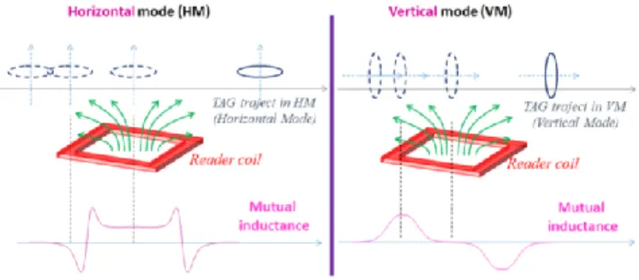
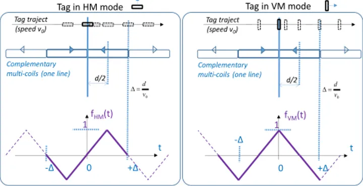
As seen in Figure 1, the glasstags used for tracking bats are based on a solenoid coil whose diameter is very small compared to its length. Consequently, the equivalent surface for quantifying the induced flux is, approximately, that of the cylindrical basis as to be the surface of a single turn, multiplied by the number of coil turns. Therefore, the glasstag remains highly sensitive to the orientation of the magnetic field. If the surface of the reader is parallel to or orthonormal to that equivalent surface, the mode of operation is horizontal (HM), respectively vertical (VM), respectively, as illustrated in Figure 2.
Figure 2 : Top - Representation of the horizontal (left) and vertical (right) mode of detection. Bottom - Variation of the mutual inductance
value when the glasstag is moving above the reader (sub-)coil.
As an arbitrary position and orientation of the tag is possible, the equivalent surface can be described geometrically by a weighted combination of HM and VM orientations. The mutual coupling, in both HM and VM, is the best parameter to optimize for detecting glasstags on bats.
1 2 12 2 1 0 r dl . dl 4π μ MThe Neumann formula in (1) involves a geometrical consideration for quantifying M. If the distance r12 between
the two elementary displacements dl1 and dl2 is high, M is
consequently low. When the coils considered for the two current paths Ψ1 and Ψ2 describe a case in which the radii are
very different, the value of M is also low (i.e. weak coupling). It follows that, for a given surface delimited by the reader coil structure, the widest reader coil is not the best solution for maximizing the detection in volume [9]. If a coil is constituted of at least a sub-coil, it is possible to reduce the distance r12
locally when computing equation (1) over the sub-path corresponding to the sub-coil [10][12]. Creating a reader with several sub-coils is called multi-coil in that paper. The use of multi-coil is the key idea herein for increasing the surface of detection by means of increasing M. This proposed structure is based on the maximization of geometrical similarity between two paths, Ψ1 and Ψ2, for a movement of Ψ2 (the
glasstag). More precisely, the multi coil structure is created by dividing the path Ψ1 into N several sub-paths, Ψ1(1,2,…N),
corresponding to a serialization of smaller sub-coils, as expressed by (2) and illustrated in Figure 3.
(2)
Figure 3 : Serialization of sub-coils defining the multi-coil structure and its equivalent surface.
Equation (2) defines the contribution of each sub-coil to the total mutual inductance value. Each M12(n) contributes to
the mutual inductance by quantifying the geometrical similarity between the glasstag coil and each of the square reader sub-coils. In our context, the optimal distance between tag and reader is between 10-15 cm, and an electromagnetic simulation helps us to determine the optimal length of each squared sub-coil. The benefit of the sub-coil serialization (i.e. multi-coil) relies on the property that each M12(n) has an
optimum value for the targeted distance of detection [1][2][13], providing the ability to detect a moving tag momentarily close to one of the sub-coils.
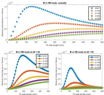
The optimal size of each sub-coil is adapted to the tag equivalent surface (radius is 1 mm, see part I). However, this sub-coil size depends also on the targeted distance of the tag and on the tag orientation. To analyze this complex tradeoff, a simulation of a squared coil, representing one of the squared sub-coil, and a circular coil, representing the glasstag equivalent surface, is done under CST, and the mutual inductance is evaluated in function of the squared Tx sub-coil length, at different distances d, as defined in Figure 1 (right).
The results of simulation are given in Figure 4 for coaxially classical case in HM (top), and for an arbitrary 50 mm displacement of the tag along the X axis in HM and VM, respectively to the orientation defined in Figure 1 (right).
The circular coil, representing the glasstag coil, is constant in size in all the simulations. The results in Figure 4 show a maximum of the mutual inductance value, M, as a function of the size of the squared sub-coil. This optimal sub-coil size is increasing with the distance while the corresponding maximum value of M is logically decreasing in magnitude. When the square and circular coils are coaxial, in Figure 4 (top), the VM mode corresponds to a null magnetic coupling, and is not reported for that reason. However, with a misalignment along X axis, dx = 50 mm in the basis defined in Figure 1 (right), the same phenomenon of optimal value for M is observed, in HM and VM, but for different optimal lengths of the squared sub-coil. The tradeoff concerning a maximum value M for both HM and VM cases simultaneously is dependent on many parameters and does not have a multi-constrained unique solution. To be able to prototype a structure for bats traceability with a target distance between 10 cm and 15 cm, we evaluate a sub-optimal interval of length values for the squared sub-coil (side length is Tx in in Figure 4). For the simulated cases in Figure 4, the interval between 200 mm and 300 mm is chosen since a minimum detection distance of 10 cm is wanted. A sub-optimal representing value is 250 mm due to the multiple tradeoffs involved in our case study.
Figure 4 : Mutual inductances values, M, from CST simulations for the two coils: (i) squared with variable length and (ii) circular with a 1mm
radius, at different distances d. Coaxial coils case (top) in HM and misaligned along X axis (dx =50 mm) cases in HM (bottom left) and
VM (bottom right)
B) Serialization of complementary coils
The sub-coil size used in the multi-coil structure has been evaluated in the previous sub-part A. To cover the maximum surface of detection, the sub-coils are serialized. This sub-part focuses on the key idea of feeding the adjacent sub-coils (i.e. with a common edge) with a current in phase or in opposite phase. Serializing adjacent sub-coils in opposite phase current is called complementary sub-coils [12][14][15].
...Ψ N Ψ Ψ Ψ Ψ Ψ r M ... M dl . dl π μ r dl . dl π μ M N 121 12 12 2 1 0 12 2 1 0 12 1 1 1 1 2 1 2 4 4
4
As seen in Figure 2, the mutual inductance between a subcoil and the equivalent surface of the glasstag coil (circular) is maximum in HM above the center (surfaces are coaxial) and maximum in VM above the edges, taking into account the sign of the induced current due to the sign of the mutual inductance value. If two adjacent sub-coils are driven with opposite phase current (i.e. complementary sub-coils), the mutual inductance value in VM is reinforced by this constructive addition above the common edge of the two sub-coils.
We simulated the mutual inductance between two squared complementary sub-coils and a circular equivalent surface. The mutual induction is a reciprocal phenomenon, involving the magnetic field integration over the surface. Movement can be then simulated by an integration and displacement of the tag or of the square sub-coils equivalently. For simplicity, we considered the tag as a single circle current path, and displaced the sub-coils, as seen in Figure 5.
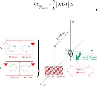
As the tag is moving along a given trajectory to illustrate the movement of bats, we define a casual figure of merit called Cumulative Coupling, CC, by equation (3), in which the trajectory is supposed from X1 to X2 along the X axis.
(3)
Figure 5 : Mutual inductances, M, for same surfaces, in function of a dX misalignment. (a) two squared sub-coils (in-phase currents) and (b)
two squared complementary sub-coils (opposite phase currents).
Figure 6 : M(x) among the trajectory of the circular coil (r=1 mm), in HM (left) and VM (right)
The value of M is computed under Matlab by summing the magnetic field components orthogonal to the orientated surface considered. The serialization of the sub-coils in phase (“a”) and in opposite phase (“b”) are illustrated by inverting the orientation of the magnetic field component used for the
computation of M. In order to reduce the processing time, the scale of the geometrical problem is reduced to a distance of 40 mm and sub-coils of 100x100 mm². Results in function of the movement along the X axis, from X1 = -200 mm to X2 =
200 mm are seen in Figure 6. CC results for surfaces “a” and “b” are given in Table 1 and reveal that complementary sub-coils achieve the highest values in both HM and VM.
Table 1 : CC values computed from the results shown in Figure 6, dimensions in cm for surface “a” (left), “b” (middle) and “c” (right)
Serializing the sub-coils in a complementary way allows an optimization of the mutual inductance value among a possible trajectory of the tags both in HM and VM. The following sub-part is focusing on the realization of such a serialization of squared sub-coils, and we also define an electrical equivalent model to evaluate the total inductance value of the reader coil in function of the number of lines, N, and columns, P, of the surface reader prototype.
C) Modeling of serialized complementary coils The prototype of serialized complementary multi-coil was realized in 2D with copper tape for high quality factor and flexibility. The structure is to be adapted to a RFID reader whose specifications imply a fixed value for the total inductance of the structure. It is first necessary to define an elementary pattern for a possible serialization of several complementary sub-coils. In Figure 7 (top), we propose such a pattern for squared coils in series for an arbitrary number of sub-coils in a line. Colored arrows are supposed to be replaced by the copper tape in the following part. The electrical model given in Figure 7 (bottom) is considering only two adjacent sub-coils, and points the value of their negative mutual inductance due to the opposite phase of the feeding current.
Figure 7 : Pattern proposed for realizing a line of complementary sub-coils in serie (top). Equivalent electrical model of two complementary
sub-coils in series (bottom)
Based on the electrical model in Figure 7 (bottom), the evaluation of the inductance for two adjacent complementary sub-coils is given by equation (4).
(4)
x dx M CC X X X X d tag
2 1 2 1, ,Movement/distance shift in meters
M ut ua lin du ct ance in H enry Verticalmode (VM) -0.2 -0.15 -0.1 -0.05 0 0.05 0.1 0.15 0.2 -1 0 1x 10 -11 -0.2 -0.15 -0.1 -0.05 0 0.05 0.1 0.15 0.2 -1 0 1x 10 -11 -0.2 -0.15 -0.1 -0.05 0 0.05 0.1 0.15 0.2 -1 0 1x 10 -11 -0.2 -0.15 -0.1 -0.05 0 0.05 0.1 0.15 0.2 -4 -2 0 2 x 10-12 -0.2 -0.15 -0.1 -0.05 0 0.05 0.1 0.15 0.2 -4 -2 0 2 x 10-12 -0.2 -0.15 -0.1 -0.05 0 0.05 0.1 0.15 0.2 -4 -2 0 2 x 10-12 Horizontalmode (HM)
Movement/distance shift in meters
HM VM 2x10x10 2x10x10 (compl.) 4e-13 H.m 4.6e-13 H.m 1.23e-12 H.m 1.66e-12 H.m V1 L1 L V2 2 M < 0 Leq (1,2) Leq (1,2) I1
L L M
j
L M
j I V V L j eq 2 2 ) 2 , 1 ( 1 2 1 2 1 The realization of a N lines by P columns prototype implies to adapt the pattern for a surface (2D). Herein, we propose to duplicate the line above, with carefully conserving the complementary sub-coils structure for the columns. This drives to the 2D pattern in Figure 8 (left) for N=2 lines and P=3 columns.
Figure 8 : Complementary multi-coil pattern for N=2 and P=3 (left) and identification of some mutual coupling to take into account for the
total inductance evaluation (right)
The observation of this 2D pattern is used for identifying the mutual inductance between some sub-coils and, as in the elementary pattern in Figure 7, evaluate the total inductance, Lequ(N,P), for any number of lines N and columns P. We
identify mutual inductances to be taken into account that have non-negligible values compared to the self-inductance, L0, of
each sub-coil.
In Figure 8 (right) there are three types of mutual coupling considered, each one being represented only once in Figure 8 for readability :
- M12 is modeling any mutual induction between two
adjacent sub-coils over their common edge, in line and in column. As these sub-coils are complementary, this coupling increases Lequ(N,P) as shown in equation (4).
- M13 is modeling the mutual induction for any couple of
two sub-coils in phase, separated by just one sub-coil in opposite phase. This coupling decreases Lequ(N,P).
- M14 is modeling the mutual induction for any couple of
two sub-coils in phase which have only a common corner. This coupling decreases Lequ(N,P).
A geometrical observation of the pattern leads to define the equation (5), establishing an empirical evaluation of the total inductance, Lequ(N,P), for a N by P structure. In (5), we can
identify the different types of mutual coupling contributions in function of N and P. For clarity, we use the coupling coefficient kij defined as Mij divided by L0.
(5) To conclude this part, a 2D pattern is proposed for serializing N by P sub-coils while keeping the complementary sub-coils property. The detection tests can be achieved if the
prototyping step is carefully taking into account the practical considerations and constraints implied by the flexibility, the movement of the tags and the RFID reader technical specifications, as detailed in part III.
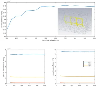
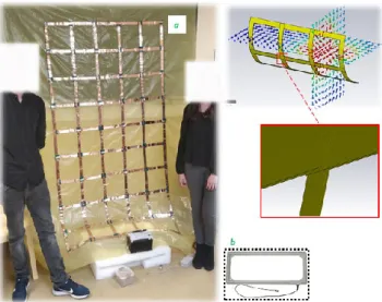
III. Practical considerations and prototype realization A) Flexibility of the reader antenna structure The fabrication of the prototype is based on the pattern presented in the previous part by fixing adhesive copper tape on a flexible and lightweight cloth. The width of the tape is 25 mm in order to be able to reach a high quality coefficient value for the total inductance of the serialized multi-coil. Additionally, this tape foil has a thickness of 70 µm, guarantying a fruitful flexibility of the structure. It is mandatory to evaluate the modification of the inductance Lequ(N,P) when the structure is bended because an effect of
curvature of a coil in free space decreases its inductance value [17]. Moreover, the evaluation of L0, M12, M13 and M14 is
necessary for a chosen side length of the squared sub-coil. As the pattern in Figure 8 is periodic due to the complementary coil property, an electromagnetic CST simulation of the elementary pattern with 6 sub-coils can evaluate the aforementioned parameters in function of different curvature radii. The side length of the squared sub–coil is set to 250 mm, according to the results of part II.
Figure 9: CST simulations of the pattern with 6 squared sub-coils, self-inductance L0 (top), mutual inductances (left) and corresponding
coupling coefficients (right), in function of the curvature radius.
In Figure 9, we can see the simulation results of varying the curvature radius from 0.1 to 1 m, which represents respectively 0.4 to 4 times the sub-coil side length. The self-inductance value of a sub-coil (250x250 mm²) without curvature, L0, is around 348 nH, and the decrease due to the
curvature [17] is only about 6% for the limit specified above, corresponding to a sub-coil covering half of the circle perimeter, which is highly constraining in terms of flexibility. Additionally, the curvature implies a variation of the coupling coefficients k12, k13 and k14 below 0.5%, which can therefore
be neglected. Consequently, the parameters used for determining the number of lines and columns of the reader coil, given by CST simulation, are set to L0 = 348 nH, k12 =
1 1 4 2 2 2 1 1 2 1 1 4 2 2 2 2 1 2 1 2 14 13 12 0 14 13 13 12 12 0 N . P k C P N. N P. k B P N. N P. k A with C B A NP L M . N . P . M . P N. M . N P. M . P N. M . N P. N.P.L (N,P) Leq M13 M12 M14 N li n es P columns Leq(N,P)
1
1
4 2 2 2 1 1 2 1 1 4 2 2 2 2 1 2 1 2 14 13 12 0 14 13 13 12 12 0 N . P k C P N. N P. k B P N. N P. k A with C B A NP L M . N . P . M . P N. M . N P. M . P N. M . N P. N.P.L (N,P) Leq6
15.8%, k13 = 0.4% and k14 = 3.8%, see Figure 9 (bottom left /right). An estimated value of the total inductance Lequ(N,P), can
be given thanks to (5) and the parameters above mentioned but there are several practical differences to point out : - The access wires will add a small inductive part which
needs to be estimated
- The number of overlapping copper tapes implies a soldering which lowers the quality factor by adding a loss resistance, see [18][19]. The number of soldering is given by Nsoldering in equation (6).
- The copper tapes have a gap between them, at each cross section and along the common edges, lower than those simulated due to the limited meshing quality, see Figure 11. Consequently, the coupling coefficients are, in practice, a bit higher than calculated.
(6) Nevertheless, it is possible to evaluate the electrical characteristics of the structure until a certain curvature radius. Coupling coefficient used in the formula (5) are not affected significantly and the variation of the sub-coil self-induction L0 is only 6% as mentioned.
B) Influence of the tag speed
The complementary multi-coil prototype goal is to detect tagged bats when flying, in the vicinity of the structure. Moreover, the tag speed is about 20 m/s and it is necessary to evaluate the variation of the magnetic flux due to this movement, because this variation is added to the variation of the magnetic flux due to the RF signal phase (i.e. term “ωt”). As the induced voltage is defined by this magnetic flux variation, the detection of the tags can be disturbed by the tag movement. However, the multi-coil structure has a length of 250 mm for each sub-coil edge which leads to a spatial variation more frequent than that caused by the use of a wide multi- turn coil (as in classical solution, see part I). The magnetic flux considered is defined in equation (7) in which the function f(t) expresses the normalized variation among the structure. The current in (7) is replaced by its sinusoidal expression. The magnetic flux in the tag coil is given by:
(7) For better clarity, we draw in Figure 10 the tag movement along a linear trajectory above the complementary multi-coil structure, at a fixed distance, in HM (left) and VM (right). In the same figure, the idealized variations of the magnetic flux (function normalized with no dimension) fHM(t) in HM and
fVM(t) in VM, are drawn while considering the tag speed
constant. The expressions of fHM(t) and fVM(t) are given by
equation (8). For a given size of the squared sub-coil edge, in Figure 10, the equation (8) expresses the flux in function of the time. Equation (7) and (8) enable to evaluate the time variation of the flux (i.e. the induced voltage) above one sub-coil in equation (9), because the variations of fHM(t) and fVM(t)
are periodic, see equation (8). This time periodicity is due to the spatial periodicity of the complementary multi-coil pattern because we supposed to have an infinity of sub-coils.
Figure 10 : Magnetic flux variations, f(t) normalized function, for a reference coil parallel (HM) and perpendicular (VM) to the complementary multi-coil structure, at a constant tag speed v0
(8)
(9) Equation (9) expresses the induced voltage due both to the influence of the RF signal and the tag movement, at a constant speed v0. The RFID detection will not be affected if we can
neglect the influence of the flux variation due to the tag movement, as is expressed by equation (10).
(10 If we consider a reference side length of 250 mm for the complementary multi-coil and a glasstag size as small as 2 mm in diameter, the speed limit corresponding to the expression in (10) is 843 m/s, which represents a margin factor of 42 compared to the bat maximum speed (20 m/s). Even if the induced voltage is mainly due to the radiofrequency signal at LF (134.2 kHz), the displacement of a tag above a serialized complementary multi-coil, leads to a significant reduction of the tradeoff margin concerning the flux variation, superior to 2% in our case. Experimentally, this can be acceptable, and even negligible for our detection tests at very low speed, but it is necessary to take this influence into account in the complete analysis.
C) Detection tests with a LF RFID reader
RFID detection tests of glasstags are performed thanks to the TIRIS RFID LF reader at 134.2 kHz. This reader is sold with a commercial rectangular 800x300 mm² loop antenna (as seen in Figure 11, bottom left) whose measured electrical characteristics are Lrect= 26.3 µH and Qrect = 67.5. Technical
2
2
2 1
2 1 4 4 NP N P N P Nsoldering
t M
t It M f
t I
ωt Φ max 0sin 0 v d 1 fHM(t) t -Δ 0 +Δ d/2 Tag traject (speed v0) 0 v d 1fVM(t) t -Δ +Δ 0 d/2 Tag traject (speed v0)Tag in HM mode Tag in VM mode
Complementary multi-coils (one line) Complementary
multi-coils (one line)
,Δ2
2 Δ - , t f t f Δ - , 0 , t f t f Δ 2kΔ t δ Δ 2kΔ t δ * t Rect Δ 2t Δ , Δ t, f 0 else, ; 2 Δ ; 2 Δ t if 1, t Rect VM HM 2 1 Δ 2 1 Δ
ωt v d ωt t ω.f I M t t f ωt t f t ωt I M t ωt I t f M t t Φ E sin 2 cos . sin sin sin 0 0 max 0 max 0 max
0 0 max 2 cos v d ω if t f ωt I M E specifications of this reader recommend an inductance value for an external antenna to be as closest as possible to 27 µH. Using equation (5) with the parameters evaluated in sub-part A, thanks to CST simulations, a total inductance of Lequ(5,9) = 22.152 µH is possible for N = 5 and P = 9. This is
the closest result for any integer values of N and P. This estimated value is still lower than the required 27 µH. However, the copper tapes have a gap between them, at each cross section and along some common edges, lower than expected, thus increasing the coupling coefficients defined in sub-part B. The prototype is shown in Figure 11.
Figure 11: Realization of the complementary multi-coils on a flexible cloth (a, in the left); commercial rectangular antenna (b, bottom). Simulations of the elementary pattern under CST (right top) and zoom on the simulated overlap between copper tape pieces (right bottom) to illustrate the order of magnitude of the approximation.
We can see in Figure 11, left, the realized complementary multi-coil fixed on a flexible cloth (structure “a”) and the rectangular commercial antenna at the bottom, structure “b”. In the same figure, the simulation under CST of the elementary pattern with 6 sub-coils is shown. In Figure 11 top right is represented qualitatively the magnetic field distribution, when feeding only one sub-coil (simulation done in order to evaluate the coupling coefficient between sub-coils). In Figure 11 bottom right, a zoom on the overlaps aforementioned is shown. This overlap is in fact over-estimated because of the accuracy of the meshing under CST. Measurements give a value of Lequ(5,9)-meas. = 26.84 µH with a
quality factor Q of 17.3. As expected, the measured value Lequ(5,9)-meas. is fruitfully higher than the theoretical value
Lequ(5,9), improving the matching with the RFID reader. In
another hand, the low value of Q can be easily explained. The mandatory number of overlaps at each cross section, Nsoldering
, that leads to 288 soldering points, evaluated for N=5 and P=9 thanks to equation (6) is quite high and the amount of copper due to the total tape length which is 288 x 250 mm = 72 m leads to additional losses. Effectively, the resistance of such copper path is hard to calculate accurately but, using equations from [18][19], we evaluate a dynamic resistance value around Rac=0.949 Ω, corresponding to a Q factor of
23.4. The difference of Q between theory and measurements may be explained by an arbitrarily evaluation of 0.3 Ω for the additional losses introduced by the multiple solderings (288) and the external connecting wires.
We performed detection tests of glasstags for comparison of the two modes. The maximum distance of detection is evaluated for a surface above each antenna in HM and VM. The volume of detection in the vicinity of both structures is represented in Figure 12.
The commercial antenna is a rectangular loop whose shape has an equivalent surface corresponding to three sub-coils of our prototype. With this antenna, the detection of a glasstag is performed up to 30 cm in HM, above the coil surface, and the same distance of detection is achieved in VM above the edge of the loop. The volumes of detection, shown in Figure 12 left top (HM) and left bottom (VM), are consequently the products of the height (0.3) by the equivalent numbers of coil surface (3x0.25²), for HM, or edge widths (copper tape width of 0.025), for VM, i.e. 0.3x3x(0.25²) = 0.0562 m3 in HM and 0.3x8x0.025x0.25 = 0.015 m3 in VM.
The serialized complementary multi-coil prototype detects the a glasstag all over all its surface at a distance of 10 cm in HM, and over all the edges of each sub-coils, at the same distance of 10 cm, in VM. The volumes of detection, shown in Figure 12 right top (HM) and right bottom (VM), are consequently 0.1xNxPx(0.25²) = 0.2813 m3 in HM and
0.1x(N(P-1)+P(N-1))x0.025x0.25 = 0.0475 m3 in VM.
Figure 12 : Volumes of detection in HM (top) and VM (bottom) for the rectangular loop (left) and the complementary multi-coil (right)
As clearly visible on Figure 12, the volumes of detection achieved for both structures are, respectively in HM and VM, 5 times and 3.16 times higher using our multi-coil prototype, with an additional advantage being its flexibility.
A tradeoff can be identified concerning the range of detection since the serialized complementary multi-coil is adapted to 10 cm only. This limit value for the range of detection is mainly due to the size of each sub-coil. Moreover, the amount of losses, quantified by the Q factor, is almost four times higher than that of the rectangular commercial antenna Qrect. By increasing the size of the sub-coils, for the same total
area, we expect to increase Q (lower copper length and less soldered overlaps) and consequently we should be able to detect the tags at a higher distance. However, the increase of the sub-coil length can bring some zeros of detection in HM mode, mainly located at the center of each sub-coils.
IV. Conclusion
This work presented the design considerations for tracking glasstags, on bats over a wide surface at a distance
8
up to 10 cm using LF RFID technology. The prototype was,step by step, justified in its design which is based on the complementary coils principle fruitfully associated to a multi-coil serialization concept. Discussions were given concerning the benefits of such multi-coil structure and the possibility to realize it on a flexible cloth with low cost adhesive copper tape. A optimal length of 250 mm for the squared sub-coil edge was evaluated by electromagnetic simulations and the processing of a Cumulative Coupling figure of merit justifies, in horizontal and vertical modes, the interest of using a complementary serialized sub-coil structure. Electrical and electromagnetic (CST) modelling of the elementary pattern lead to define an empirical formula giving the total inductance of the complementary multi-coil serialization structure.
The inductance was set to the value corresponding to a commercial RFID reader (TIRIS) technical specification. Measurements were performed to compare the CST simulations and the empirical formula evaluating the coil inductance and its quality factor. Detection performances of glasstags with the proposed prototype were done, and compared with those obtained using a commercial rectangular RFID antenna as reference. Results show that the complementary multi-coil structure reaches a volume of detection much higher than the one of the rectangular antenna, both in HM (5 times) and VM (3.16 times) cases.
Finally, a tradeoff was identified between the detection range, the coverage ability and the quality factor for a given antenna total area. This can lead to a new design if the detection range has to be increased in function of the application.
ACKNOWLEDGMENTS
The authors want to thank the two students of the IUT de Cachan, Mailys Martin and Paul Vanetti, who fruitfully helped in the realization of the prototype and performed the numerous solderings.
REFERENCES
[1] K. Finkenseller, RFID Handbook: Radio-frequency Identification fundamentals and application, 2nd edition, Wiley, 2003.
[2] D Parret, RFID and Contactless Smart Card Applications.
Wiley-Blackwell, 2005, ISBN-10/13: 0470011955 / 978-0470011959.
[3] R. E. Floyd, "RFID in Animal-Tracking Applications," in IEEE Potentials, vol. 34, no. 5, pp. 32-33, Sept.-Oct. 2015. doi: 10.1109/MPOT.2015.2410308
[4] Smyth, B. & Nebel, S. (2013) Passive Integrated Transponder (PIT) Tags in the Study of Animal Movement. Nature Education Knowledge 4(3):3.
[5] Sheryan P. Epperly, Lesley W. Stokes, Lisa C. Belskis. Radio-Frequency Identification Technology and Marine Turtles: Investigation of Passive Integrated Transponder (PIT) Tags and Readers. Marine
Turtle Newsletter No. 145, 2015 - Page 4-15.
[6] S.Mirbozorgi, H.Bahrami, M.Sawan,B.Gosselin , “A Smart Cage With Uniform Wireless Power Distribution in 3D for Enabling Long-Term Experiments With Freely Moving Animals”, IEEE Transactions on
Biomedical Circuits and Systems, vol.10, no.2, pp 424 - 434, 2016.
[7] S.A.Mirbozorgi, P.Yeon, M.Ghovanloo, “Robust Wireless Power Transmission to mm-Sized Free-Floating Distributed Implants”, IEEE
Transactions on Biomedical circuites and systems, Vol. 11, no. 3,
692-702, 2017.
[8] http://www.reseau-cen.org/fr/les-programmes/ le-plan-national-d-actions-en-faveur-des-chiropteres
[9] B.H. Waters, B. J. Mahoney, G. Lee and J. R. Smith, “Optimal Coil Size Ratios for Wireless Power Transfer Applications”, IEEE
International Symposium on Circuits and Systems (ISCAS), June 2014,
pp. 2045-2048.
[10] X. Wang, H. Wang and G. Wang, "Distributed High-Frequency RFID Antennas for Smart Storage Racks," 2010 Second International
Conference on Networks Security, Wireless Communications and Trusted Computing, Wuhan, Hubei, 2010, pp. 472-474. doi: 10.1109/NSWCTC.2010.244.
[11] M. Salhi, M. Benamara, M. Grzeskowiak, G. Lissorgues, A. Diet, Y. Le Bihan. Antenna array in 3D HF RFID to improve tracking small tag.
IET Microwaves, Antennas & Propagation, Vol. 12, I. 5, pp 678-683, 2018, ISSN 1751-8733 / 1751-8725, DOI: 10.1049/iet-map.2017.0540.
[12] A. Diet, M. Grzeskowiak, Y. Le Bihan, C. Conessa. Improving LF Reader Antenna volume of detection for RFID token tag thanks to Identical Coaxial Loops (ICLs) and in/out-of phase multiple-loops structures. IEEE International Conference on RFID-Technology and
Applications 2014, IEEE RFID-TA, 2014 sept. 8-9, Tampere, Finland, ISBN: 978-1-4799-4680-8/14, pp. 208-213.
[13] A. Diet, M. Grzeskowiak, Y. Le Bihan, M. Biancheri-Astier, M. Benamara, K. Gbafa, C. Conessa, G. Lissorgues, F. Alves, A. Pozzebon. A switched reader complementary-loops structure for detecting LF RFID tagged pebbles. IEEE International Conference on
RFID-Technology and Applications 2017, IEEE RFID-TA, 2017 sept. 20-22, Warsaw, Poland, session A3-3.
[14] M. Grzeskowiak, A. Diet, M. Benamara, C. Conessa, S. Protat, M. Biancheri-Astier, F. de Oliviera Alves, Y. Le Bihan, G. Lissorgues. Enhanced HF RFID detection area of mobile small tag via Distributed Diameter Coil resonator. Progress In Electromagnetics Research C,
PIER C, ISSN: 1937-8718, Vol. 82, 237-249, 2018.
[15] Kamineni, G-A. Covic, J-T. Boys “Analysis of Coplanar Intermediate Coil Structures in Inductive Power Transfer Systems", IEEE
Transactions on Consumer Electronics, 2015, 30, (11), pp.6141-6154
[16] K. Fotopoulou, B. W. Flynn, “Wireless Power Transfer in Loosely Coupled Links: Coil Misalignment Model”, IEEE Transactions on
Magnetics, vol.47, no.2, pp.416-430, 2011.
[17] S.K. Burke, R.J. Ditchburn, T.P. Theodoulidis, Impedance of a curved circular spiral coil around a conductive cylinder, NDT & E
International, Volume 64, 2014, Pages 1-6, ISSN 0963-8695, https://doi.org/10.1016/j.ndteint.2014.02.002.
[18] S. J. Haefner. Alternating-Current Resistance of Rectangular Conductors. Proceedings of the Institute of Radio Engineers, Volume
25, No 4, April 1937.
[19] J. D. Cockcroft. Skin Effect in Rectangular Conductors at High Frequencies. Proceedings of the Royal Society, Vol 122, February 1929.