HAL Id: hal-01892674
https://hal-univ-perp.archives-ouvertes.fr/hal-01892674
Submitted on 2 Mar 2021
HAL is a multi-disciplinary open access archive for the deposit and dissemination of sci-entific research documents, whether they are pub-lished or not. The documents may come from teaching and research institutions in France or abroad, or from public or private research centers.
L’archive ouverte pluridisciplinaire HAL, est destinée au dépôt et à la diffusion de documents scientifiques de niveau recherche, publiés ou non, émanant des établissements d’enseignement et de recherche français ou étrangers, des laboratoires publics ou privés.
Design and optimization of baffled fluid distributor for
realizing target flow distribution in a tubular solar
receiver
Min Wei, Yilin Fan, Lingai Luo, Gilles Flamant
To cite this version:
Min Wei, Yilin Fan, Lingai Luo, Gilles Flamant. Design and optimization of baffled fluid distributor for realizing target flow distribution in a tubular solar receiver. Energy, Elsevier, 2017, 136, pp.126 -134. �10.1016/j.energy.2016.04.016�. �hal-01892674�
1
Design and Optimization of Baffled Fluid Distributor for Realizing Target
Flow Distribution in a Tubular Solar Receiver
Min WEIa, Yilin FANa, Lingai LUOa*, Gilles FLAMANTb
a Laboratoire de Thermocinétique de Nantes, UMR CNRS 6607, Polytech' Nantes –
Université de Nantes, La Chantrerie, Rue Christian Pauc, BP 50609, 44306 Nantes Cedex 03, France
b Laboratoire PROcédés, Matériaux et Energie Solaire (PROMES), UPR CNRS 8521, 7 rue
du Four Solaire, 66120 Font-Romeu Odeillo, France
Abstract
This paper presents an original study on the design and optimization of baffled fluid distributor for the realization of optimal fluid flow distribution in a tubular solar receiver. The basic idea is to install a perforated baffle in the inlet fluid distributor and to optimize the configuration of orifices on the baffle so as to approach the target flow distribution among downstream parallel tubes. A pressurized-air solar receiver comprising of 45 parallel tubes is used for study, with copper or Inconel 600 used as the filling material.
Results show that the final fluid flow distributions realized by the geometrically optimized baffles are in good agreement with the target curves. The peak temperature of the receiver wall can be minimized accordingly with moderate increase in total pressure drop of the receiver system. It is shown that the insertion of a geometrically optimized baffle is generally a practical solution with various features: capable of realizing non-uniform target distribution; small pressure drop increase; compact geometry; flexible and adaptive; easy fabrication with a reasonable cost, etc.
Keywords: Flow distribution; Tubular solar receiver; Perforated baffle; Optimization
method; Pressure drop
2
1. Introduction
Nowadays, climate change, diminishing world energy resource and increasing energy cost stimulate the diversification of renewable and sustainable energies and the innovation in the industry (Olabi, 2012, 2013; Danielewicz et al., 2014). Solar energy, especially Concentrated Solar Power (CSP), is considered as one of the promising alternatives to conventional fossil sources. As a key component in current commercial or experimental CSP projects, tubular-type solar receiver is widely used because of its relatively low cost and long lifetime (Grange et al., 2011; Li et al., 2013; Baroutaji et al., 2015; Boerema et al., 2013; Wang et al., 2015). However, the problem of fluid flow maldistribution is frequently encountered in CSP solar receivers due to their multi-tubular or multi-level configurations.
In the literature, investigations have conclusively shown that the receiver’s efficiency decreases when the flow distribution of heat transfer fluid among parallel tubes becomes less uniform (Chiou 1978; Jones, 1987; Jones and Lior, 1994; Gunnewiek et al., 2002; Karwa et al., 2007; etc). For example, Chiou (1982) found that the performance deterioration could be higher than 20% due to non-uniform flow distribution under some operation conditions. Wang and Wu (1990) studied the performance of flat-plate solar collector arrays and also confirmed that the efficiency decreased about 15%-30% due to the flow non-uniformity. Fan and Furbo (2007) reported that non-uniform flow distribution can lead to boiling problems in the strips of flat-plate solar receiver, which may result in physical damage or acidification corrosion on the receiver. Moreover, another particular negative effect due to flow maldistribution is the presence of “hot spots” on the receiver walls. The high thermal-mechanical stress caused by local overheating will lead to the mechanical failure or reduced lifetime of solar receivers by a factor of 10 to 20 (Fork et al., 2012; Salomé et al., 2013).
However, the heat flux distribution on the receiver wall is not always as uniform as assumed. Actually non-uniform heat flux has been observed both numerically and experimentally in laboratory PROMES, France. For example, a dish/Stirling system "EuroDish" which has a complete mirror of 53.1 m2 had been tested experimentally
(Reinalter et al., 2008) and numerically (Caliot et al., 2015), and a Gaussian-like heat flux distribution on the focal plane was observed. Salomé et al. (2013) took the pictures by a high resolution CCD camera for the distribution of concentrated solar flux on the absorber. As a qualitative study, 30 heliostats were used to reflect the full moon light which was similar to sun shape to a single centered aiming point. They reported that the flux density distribution delivered on the measurement target was also Gaussian-like.
Based on the fact of non-uniform heat flux on the solar receiver reported above, some studies (Boerema et al., 2013; Wei et al., 2015a) reported that uniform fluid flow distribution among parallel tubes of solar receivers may not be the optimal option. Boerema et al. (2013) proposed an optimality criterion to optimize the fluid flow distribution among parallel tubes, suggesting that the peak temperature on the heated surface can be reduced by equalizing the
3
outlet fluids temperatures from parallel tubes. The analytical results obtained showed that the ideal (optimized) fluid flow distribution can reduce the peak temperature by more than 200 °C. However, no clue indicated that the peak temperature was minimized. In our earlier study (Wei et al., 2015a), an original CFD (Computational Fluid Dynamics) -based evolutionary algorithm has been developed for the determination of the optimal fluid flow distribution in a tubular solar receiver subjected to a non-uniform net heat flux, so as to minimize the peak temperature on the receiver wall. Different shapes of optimal fluid distribution which are not uniform can be determined corresponding to different filling materials (varied thermal conductivity). The peak temperature on the heated surface can be reduced by about 240 K when Inconel 600 is used as the filling material, simply by optimizing the fluid flow distribution among parallel tubes. Nevertheless, our earlier study (Wei et al., 2015a) focused on how to determine the optimal fluid flow distribution while how to realize such optimal distribution still remained as an open question.
Therefore, one interesting issue with practical significance is the design and optimization of fluid distributor (and/or collector) for providing the already determined target (optimal) fluid distribution among parallel tubes. The fundamental design question is how to configure the distributor/collector so as to satisfy several important features at the same time:
• Target flow distribution which is not necessarily uniform;
• Small pressure drop increase which is related to the mechanical power consumption and the performance of downstream thermodynamic cycles;
• Compact for space saving;
• Flexible and adaptable to various geometries of the solar receiver and different operational conditions;
• Easy manufacturing and reasonable cost.
In the past two decades, different types of flow distribution management devices have been proposed (Rebrov et al., 2011; Luo et al., 2015), including the use of fluid distributor/collector with optimized geometrical parameters (e.g., Commenge et al., 2002; Tondeur et al., 2011; Pistoresi et al., 2015), the use of nature-inspired tree-like structures (e.g., Luo et al., 2007; Yue et al., 2010; Tarlet et al., 2014), and adding "packings" as additional hydraulic resistance inside the distributor/collector (e.g., Rebrov et al., 2007; Chen, 2010). As an improvement of "packings" method, the insertion of a perforated baffle in the inlet fluid distributor is also widely employed, as summarized in Luo et al. (2015). However, all these methods, either cost-effective or expensive, are only capable of approaching the uniform distribution among parallel channels or tubes (e.g., Lalot et al., 1999; Jiao et al., 2003; Wen et al., 2006). To the best of our knowledge, the only attempt in the literature for realizing non-uniform but target fluid flow distribution was reported in our recent paper (Wei et al., 2015b), by installing a geometrically optimized perforated baffle at the distributing manifold. Results showed that different target curves (either uniform or non-uniform) could be successfully reached, but the numerical examples investigated were restricted to a 2D domain
4
without considering heat transfer. Although some clues for the extension of the optimization method to 3D components may be found in Luo et al. (2015), the application with actual physical background and systematic investigations are still lacking.
As an important follow-up work of our previous study (Wei et al., 2015a), this paper presents an original study on the design and optimization of baffled fluid distributor for the realization of optimal fluid flow distribution in a CSP tubular receiver. Based on the practical background of CSP engineering application, this study attempts to demonstrate a complete approach in this field, by considering coupled heat transfer and fluid flow in real 3D geometries. As our optimization objective, the peak temperature on the receiver wall could be minimized accordingly by using the geometrically optimized baffle.
In the rest of this paper, we will first introduce the geometry of tubular solar receiver equipped with an inlet fluid distributor and an outlet fluid collector. Then two optimal fluid flow distributions already determined in (Wei et al., 2015a) using copper and Inconel 600 as the filling materials will be selected as the target curves to be realized by optimizing the configurations of perforated baffles. Detailed discussions will be devoted to the reduced peak temperature on the heated surface and the increased total pressure drop due to the insertion of the optimized perforated baffle. Finally, remarks and main conclusions will be summarized.
2. Solar receiver device and optimization method
In this section, the tubular solar receiver system equipped with the distributor and the collector will be briefly introduced. The optimization principles for the perforated baffle and the CFD simulation parameters will be presented as well.
2.1 Geometry of tubular solar receiver with distributor and collector
Figure 1 shows the geometry of the integrated tubular solar receiver system used in this study. It is composed of three parts: inlet rectangular baffled fluid distributor, tubes-in-matrix receiver and outlet rectangular fluid collector. The core part of the system is a cuboid solid monoblock, with the overall dimensions of 405 mm in length (z direction), 202 mm in width (x direction) and 49 mm in height (y direction). It is based on the tube-in-matrix concept, consisting of the external shell, the filling material and a bunch of parallel straight tubes. The external shell and the walls of tubes are made of Inconel 600 while the filling material could be different (copper for example). In more detail, 45 straight tubes with 6 mm in internal diameter and 405 mm in length are arranged symmetrically in three aligned layers. For the convenience of description, these tubes are indexed by i as layer A to C from top to bottom, and by j from 1 to 15 along the x direction. Detailed configuration and dimensions of the tubes-in-matrix part can be found in Wei et al. (2015a).
5
Figure 1: Schematic view of the tubular solar receiver equipped with an inlet fluid distributor and an outlet fluid collector.
The inlet baffled fluid distributor has a single inlet port in the center with 20 mm in diameter and 40 mm in length, as shown in Fig. 2. Connected to the inlet port is a rectangular distributing manifold with 202 mm in width, 49 mm in height and 30 mm in length. A perforated baffle is inserted in the distributing manifold, with the thickness (e) of 8 mm for sufficient mechanical strength. The overall dimension of the perforated baffle corresponds to the distributing manifold, while the configuration of orifices on the baffle is to be optimized for providing target fluid flow distribution among the downstream 45 parallel tubes. The endpoints of parallel tubes are connected to the outlet fluid collector which has the same geometry and dimension of the distributor, but without baffle insertion.
In actual operation, pressurized air at 15 bar with a constant mass flow-rate will be introduced to the inlet port of distributor, spread by the perforated baffle with optimized configuration, then heated up by passing inside the parallel tubes and finally resembled by the outlet fluid collector. Note that the rectangular-shape distributor and collector are proposed as a study example for compactness consideration. The optimization method for orifices’ configuration is fully compatible with other possible geometries (conic or curvature shape) of the distributor/collector.
6
Figure 2: Geometry and dimensions of the baffled inlet fluid distributor (unit: mm).
2.2 Optimization principles for perforated baffle
The basic idea of the optimization method is to adjust the size of orifices on the perforated baffle so as to approach the target mass flow-rate in every downstream parallel tube. For 3D devices, the baffle is divided into a number of virtual control groups, each control group corresponding to one downstream straight tube, as shown in Fig. 3. In each control group, N orifices are evenly distributed on the baffle.
Figure 3: Division of control groups.
We annotate the mass flow-rate passing through the ijth tube as mij and its target value as
m'ij. Based on mass conservation, we obtain:
15 15 1 1 C C ij ij i A j i A j m m m = = = = ′ =
∑∑
=∑∑
(1) m m M = (2) where m is the total mass flow-rate of heat transfer fluid, m the mean mass flow-rate among7
all parallel tubes, and M is the total amount of parallel tubes (M=45 in this study).
The fluid mass flow-rate in every orifice and in every straight tube may be obtained by running the CFD simulation of the entire solar receiver system equipped with fluid distributor and collector. Then the diameter of orifices in ijth control group dij will be varied
simultaneously by comparing mij and m'ij in the corresponding ijth tube. More precisely, if mij
is higher than its target m'ij, the sizes of the orifices dij become smaller to reduce the flow-rate
passing through the ijth tube, and vice versa. According to the repetitive nature of the variation process, an automatic iteration program is developed to realize the evolutionary procedure until the objective is achieved. The implementation of the algorithm is described in detail in Wei et al. (2015b).
In the present study, the increment or decrement of the orifice’s diameter dij from t to t+1
iteration is determined by a variation rule presented in Eq. (3) which is a specific form of Ref. (Luo et al., 2015), based on the difference between mij and its target value m'ij:
, , 2 , 1 , ij t ij t ij t ij t m m d d m γ + ′ − = + (3) γ is a relaxation factor always greater than zero introduced to control the speed of variation. Following this variation rule, the global porosity of the baffle Φ defined as follows is kept constant during the iterations:
15 2 1 4 C ij i A j N d S π = = Φ =
∑∑
(4) where S is the surface area of baffle.To quantify the degree of closeness between the target distribution curve and the final flow distribution achieved by optimization, the parameter maldistribution factor (MF) is defined as follows: 2 15 1 1 MF 1 C ij ij i A j m m M = = m ′ − = −
∑∑
(5) Note that Eq. (5) could be considered as a generalized form of “maldistribution factor” initially used in the literature (e.g., Fan et al., 2008; Guo et al., 2014) to quantify the flow non-uniformity. The main difference lies in that m is replaced by m′ij in the numerator of the summation items in Eq. (5), to evaluate the deviation between the current mass flow-rate and its target value in each tube. The target flow distribution is considered to be completely reached when the values of MF approach 0. In the current study, the optimization process will be terminated when the value of MF becomes smaller than 0.1.8
2.3 Numerical parameters for CFD simulation
In this study, simulations were performed under steady state and the gravity effect was considered. Note that half of the real object was actually simulated for the purpose of lessening the computational burden. Structured meshes were generated for the fluid zone using software ICEM (version 12.1) whereas unstructured meshes were constructed for the solid zone. The implemental mesh involved about 4 255 980 cells and was applicable to our simulations after a grid independence test.
The working fluid used in this study was pressurized air at 15 bar, with constant total inlet mass flow-rate of 135 g s-1. Two materials (copper and Inconel 600) were used as the
filling materials for comparison. The temperature dependent physical properties of fluid and solid under the tested conditions may be found in Wei et al. (2015a).
Coupled fluid flow and heat transfer were simulated using a commercial code FLUENT (version 12.1.4), by solving Navier-Stokes equations and heat transfer equations. The fluid flow was calculated by the COUPLED method for pressure-velocity coupling, and a second order upwind differential scheme was applied for the spatial discretization. For the fluid zone, the inlet boundary condition was set as mass flow-rate of air at 300 K normal to the boundary of the distributor’s inlet port whereas the pressure outlet boundary was set for the outlet port of collector with the gauge pressure value being zero. Standard k-ε model was used to predict turbulent flow. For the solid zone, a Gaussian-shape net heat flux was defined for the heated surface of the solar receiver. Details for this net absorbed heat flux distribution may be found in Fig. 3 of Ref. (Wei et al., 2015a), with the maximum local heat flux being 650 kW m-2 and
the average heat flux of the whole surface being 284.6 kW m-2. All the tube walls were
defined as non-slip conditions with negligible thermal contact resistances. Other walls of the system were considered as adiabatic with negligible heat loss to the environment.
At each optimization step, MATLAB was used to take the computed flow field results from FLUENT, to perform calculations of the coordinates of simulation domain and to pass the data required to ICEM to regenerate the mesh for the updated geometry.
2.4 Initial baffle design and target curves
The initial orifices’ configuration of the baffle subjected to optimization is shown in Fig. 4. 45 orifices (N=1) with identical initial diameter of 4 mm are evenly distributed on the baffle surface, the global porosity thus being 5.71%. The distance between the perforated baffle and the inlets of parallel tubes is 2 mm.
9
Figure 4: Geometry and dimensions of the initial (uniform) perforated baffle for optimization (unit: mm).
The target curves to be realized by optimizing the baffled fluid distributor have already been determined in Wei et al. (2015a), with the purpose of minimizing the peak temperature (Tpeak) of the receiver wall. Here two target distributions with Inconel 600 or copper used as
the filling material are selected as examples. Due to different thermal conductivities of the filling material, the shapes of these two target distributions are differed from each other, as shown in Figs. 6 and 9 of the present article.
3. Results and discussion
3.1 Copper used as the filling material
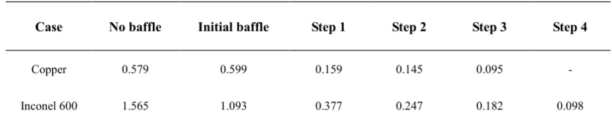
Using the proposed optimization method, the optimized configuration of perforated baffle can be obtained, as shown in Fig. 5. The orifices located in the peripheral areas of the baffle are small, corresponding to low flow-rates in downstream tubes. Although the target flow-rate in the center is high, the size of corresponding orifice should be reduced because it faces directly to the inlet port of the distributor. After 4 steps of optimization process, the MF value decreases from 0.579 (without baffle) to 0.095. The variation of MF value along the optimization steps is indicated in Table 1. The final flow distribution by insertion of the optimized baffle is in good agreement with the target curve, as shown in Fig. 6.
Figure 5: Optimized configuration of the perforated baffle for solar receiver using copper as the filling material (diameter, unit: mm).
Table 1: MF values in the optimization process.
Case No baffle Initial baffle Step 1 Step 2 Step 3 Step 4
Copper 0.579 0.599 0.159 0.145 0.095 -
10
Figure 6: Comparison between the final flow distribution with optimized baffle and the target curve (copper as the filling material).
Figure 7 shows the fluid flow distribution and the corresponding temperature field on the heated surface with insertion of the optimized baffle (Fig. 7b) compared to those without any baffle insertion (Fig. 7a). When no baffle is used, the highest mass flow-rates are located in central tubes (A8, B8, C8, etc.), the corresponding peak temperature (Tpeak) of the heated
surface being 753.2 K and a temperature difference of 324.8 K between the maximum and the minimum. Obviously, the temperature field is still Gaussian-like due to the Gaussian-shape net heat flux absorbed by the receiver. By providing the optimal fluid flow distribution among parallel tubes using the optimized baffle, the isothermal lines on the heated surface are generally perpendicular to the direction of fluid flow, implying a minimized Tpeak value of
747.8 K. The max-min temperature difference is also reduced to 317.5 K. In fact, the target (optimal) flow distribution was determined by the optimality criterion of identical temperatures on the centerline perpendicular to the fluid flow direction. Note that the optimized temperature distribution on the heated surface and the minimized Tpeak value are
very close to those presented in Fig. 8 of Ref. (Wei et al., 2015a), indicating the effectiveness of the optimized baffle insertion method for realizing the target flow distribution.
Meanwhile, the total pressure drop (∆ptotal) of the receiver system increases by 21.7%
from 17442 Pa (without baffle) to 21230 Pa (with optimized baffle). In order to modulate the initial fluid flow distribution (Fig. 7a) to its optimal shape (Fig. 7b), extra mechanical power should be consumed due to the additional hydraulic resistance of the baffle. Nevertheless, its increase due to the baffle insertion is relatively small (<0.04 bar).
11
Figure 7: Fluid flow distribution among parallel tubes and the corresponding temperature field of the heated surface (copper as the filling material): (a) without baffle insertion; (b) with insertion of optimized baffle.
The pressure drop values at different parts of the solar receiver are presented in Fig. 8. Note that the subscripts dis, tubes and col represent the distributor part, the tubes-in-matrix part and the collector part, respectively. It can be observed that the pressure drop in the distributor part (∆pdis) increases from 46 Pa to 5865 Pa due to the baffle insertion. The ratio
of ∆pdis with respect to ∆ptotal augments from 0.26% to 27.5%. Meanwhile, ∆ptubes (average
value among parallel tubes) decreases from 1982 Pa to 310 Pa because of relatively more uniform flow distribution among parallel tubes. Another observation is that the pressure drop in the collector (∆pcol) seems to be the major contribution to ∆ptotal for both cases with or
without baffle insertion. In fact, the specific volume of pressurized air increases when it is heated up inside the parallel tubes. The volume flow-rate (thus the velocity) of air in the collector part is much higher than that in the distributor part, resulting in much higher value of ∆pcol. This also implies that the simple rectangular-shape collector used in this study is
clearly not an optimal design and can be further improved. Nevertheless, the optimization method is fully compatible with other possible shapes of the fluid collector. Different configurations of the optimized baffle can be obtained regarding different geometries of collector, while the target fluid flow distribution can always be reached.
12
Figure 8: Pressure drop values on different parts of the solar receiver system (copper as the filling material): (a) without baffle insertion; (b) with optimized baffle insertion.
It should be noted that due to relatively high thermal conductivity of copper (about 380 W m-1 K-1), the reduction of Tpeak by optimizing the fluid flow distribution is not significant
(from 753.2 K to 747.8 K). To further verify the optimization method, another case with Inconel 600 used as the filling material (thermal conductivity about 20 W m-1 K-1) is tested
and will be presented in the following sub-section.
3.2 Inconel 600 used as the filling material
As shown in Fig. 9, the target curve for this case is much less regular: almost all fluids should be allocated in layer A which is the closest to the heated surface. This implies a large flow gradient between the layer A and the layer B, as well as a number of empty tubes (m'ij=0) in layers B and C. These features of the target curve set higher requirements for the
optimized baffle so that the results obtained by performing the standard optimization procedure (such as for the copper case) may be less satisfactory. Therefore, some special treatments should be added as useful complementary to the proposed optimization method.
For the actual optimization of the perforated baffle, the tubes with zero flow-rate are firstly blocked in the CFD simulation and the corresponding orifices are removed. Then, a partition wall is added in the middle of layer A and layer B, in order to prevent the transversal flow flux. The height of partition wall is 2 mm, corresponding to the distance between the perforated baffle and the inlets of parallel tubes, as shown in Fig. 10b.
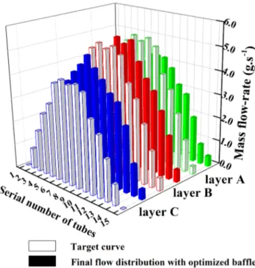
By performing the optimization method, the target flow distribution (shown in Fig. 9) could be reached, indicated by the reduced MF value from 1.565 (without baffle) to 0.098 in 5 steps (Table 1). Fig. 10a shows the optimized configuration of the perforated baffle. It may be observed that the orifices located in layer A are significantly larger than those in layer B, corresponding to higher flow-rates of the target curve on layer A.
13
Figure 9: Comparison between the final flow distribution with optimized baffle and the target curve (Inconel 600 as the filling material).
(a)
(b)
Figure 10: Optimized baffled fluid distributor for the tubular solar receiver when Inconel 600 is used as the filling material: (a) optimized baffle configuration (diameter, unit: mm); (b) distributor geometry.
For the filling material of Inconel 600 with relatively low thermal conductivity (about 20 W m-1 K-1), the shape of fluid flow distribution among parallel tubes could have a great
14
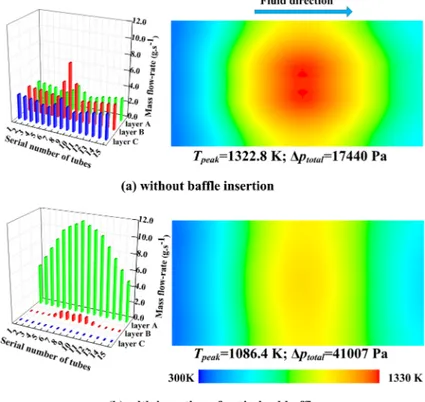
receiver. The temperature field on the heated surface presents an obvious Gaussian-shape without baffle insertion, while it is much more uniform after the insertion of the optimized baffle. Comparing to the case of distributor without baffle, the Tpeak value is reduced from
1322.8 K to 1086.4 K by using the optimized baffled distributor, as shown in Fig. 11. The reduction on Tpeak (about 240 K) is rather significant by providing the optimal flow
distribution among parallel tubes. Meanwhile, the temperature difference between the maximum and the minimum is also reduced from 950.8 K to 725.3 K.
Figure 11: Fluid flow distribution among parallel tubes and the corresponding temperature field of the heated surface (Inconel 600 as the filling material): (a) without baffle insertion; (b) with insertion of optimized baffle.
For the case of empty distributor without baffle insertion, the total pressure drop ∆ptotal of
the system using Inconel 600 as the filling material reaches 17440 Pa, very close to that using copper (17442 Pa). However, the ∆ptotal increases from 17440 Pa to 41007 Pa due to insertion
of the optimized baffle. This moderate increase of pressure drop (about 0.24 bar) is mainly due to the highly irregular character of the target distribution curve. As a result, the benefit of
Tpeak reduction is at the cost of higher total pressure drop of the system.
The pressure drops at different parts of the receiver system are indicated in Fig. 12. It may be clearly observed that the increase of pressure drop in the distributor part (∆pdis from
60 Pa to 24417 Pa) is the main reason of the increased ∆ptotal, i.e., the ratio of ∆pdis to ∆ptotal
augments from only 0.34% to 59.5%. In fact, to realize the highly irregular target curve, a number of orifices on the baffle have to be blocked, leading to a smaller global porosity on the baffle (2.79%). Meanwhile, ∆pcol (about 15 kPa) also contributes a lot to ∆ptotal for both
cases with or without baffle insertion, mainly due to the non-optimized design of the fluid collector.
15
Figure 12: Pressure drop values on different parts of the solar receiver (Inconel 600 as filling material): (a) without baffle insertion; (b) with optimized baffle insertion.
4. Discussions
The present study concerns the realization of the optimal fluid flow distribution in a tubular solar receiver, while the optimal distributions (target curves) have already been determined in our earlier study (Wei et al., 2015a). The temperature fields on the heated surface and the Tpeak values obtained in this study are generally in good agreement with those
in Wei et al. (2015a). Nevertheless, small differences can still be observed between the two studies, e.g., minimized Tpeak value of 747.8 K instead of 762.8 K for the copper case and
1086.4 K instead of 1094.0 K for the Inconel 600 case. This is mainly due to the fact that only the tubes-in-matrix part has been considered in Ref. (Wei et al., 2015a) while the entire solar receiver system equipped with the distributor and the collector is taken into account in the present study. A small amount of the heat absorbed by the heated surface will inevitably be transferred to the distributor and the collector parts, and then to the pressurized air passing through. Hence, slightly smaller minimized Tpeak values are obtained in this study than those
in Ref. (Wei et al., 2015a), notwithstanding the identical net heat flux absorbed by the heated surface of the tubes-in-matrix part.
The optimized baffle insertion in the fluid distributor can effectively reduce Tpeak of the
solar receiver, but at the cost of higher ∆ptotal of the system. In fact, extra mechanical energy
has to be consumed to modulate the initial fluid flow distribution toward the target shape. However, a great proportion of total pressure drop is generated in the rectangular fluid collector whose geometry is not yet optimized. By simply using conic or curvatured shape collector, the total pressure drop of the system could be further reduced. Note that the proposed optimization method is compatible with other shapes of distributor/collector; only the final configuration of the optimized baffle will be varied correspondingly. In summary, realizing a certain target flow distribution with the minimum increase of pressure drop is certainly an interesting topic of practical significance, by introducing multi-criteria optimization methodologies.
16
By examining Figs. 6 and 9, it could be seen that the flow distributions provided by optimized baffles are globally in nice agreement with the target curves. Small deviations may be observed for several individual tubes, mainly due to the termination criterion selected in this study (MF<0.1) for the optimization method. When better agreement to the target curve is requested, smaller values of MF could be considered as the termination criterion but more optimization steps (thus longer computational time) will be needed. For some extreme cases when highly irregular target curves are involved, some actions should be taken as useful complementary to the optimization method, including the partition walls or a second header. Moreover, the perforated baffle to be optimized may also be integrated as inlet openings of the parallel tubes.
It should be noted that the proposed optimization method is based on the results of CFD simulation. Therefore, the difficulties occurred in simulation, such as for highly turbulent or complex fluid (e.g. non-Newtonian), will influence inevitably the effectiveness of our method. Selecting appropriate and adaptive CFD codes or models is essential for precise calculation of the flow and temperature fields. Besides common commercial CFD codes, we may turn to some in-house codes or advanced numerical techniques such as the lattice Boltzmann method (Wang et al., 2014). Deep understandings on fundamental physical phenomena and on conjugated heat and mass transfers should be firstly acquired for the implementation of the optimization method.
In this study, some technical problems such as fabrication tolerances, fouling, contact thermal resistances are ignored to reduce the complexity of physical problems. However, the factors having great influences could be considered in the CFD simulation or in the optimization process. If we already know the variation of tube diameter due to fabrication tolerances, we could take the exact dimensions into account at the beginning when creating and meshing the object. As far as the fouling or contact thermal resistances are concerned, boundary conditions for the relative tube might have to be modified accordingly. For the variation in fluid composition, the physical properties of working fluid should be well defined to reflect the reality.
5. Conclusion and perspectives
In this article, an original study on the design and optimization of baffled fluid distributor is presented for the realization of optimal fluid flow distribution in a CSP tubular receiver. The optimization method proposed adjusts the sizes of orifices on the baffle inserted in the distributing manifold so as to approach the target flow-rate among parallel tubes. Two optimized baffles are then obtained, with copper or Inconel 600 used as the filling material. Based on the results obtained, main conclusions can be summarized as follows:
The optimization method is effective for reaching the optimal configurations of the perforated baffle. The final fluid distributions provided by the optimized baffles are in good agreement with the target curves, with the values of maldistribution factor (MF) smaller than 0.1.
17
The peak temperature on the receiver wall can be minimized accordingly by optimizing the flow distribution. Tpeak on the heated surface can be reduced from
753.2 K to 747.8 K for the copper case, and from 1322.8 to 1086.4 for the Inconel 600 case.
The total pressure drop of the solar receiver system with insertion of optimized baffle is about 0.21 bar for the copper case, and about 0.41 bar for the Inconel 600 case. The pressure drop increase due to the baffle insertion is relatively moderate (0.04 bar for the copper case; 0.24 bar for the Inconel 600 case).
Our future work will focus on the experimental tests of a real tubular solar receiver which is an essential step for the validation of the optimization method and the numerical results. The tubular solar receiver equipped with optimized baffled flow distributors will be fabricated and tested. The measurement of temperature distribution on the heated surface will indicate the improvement of temperature uniformity and the reduction of peak wall temperature. Also, a series of perforated baffles can be designed under different typical working conditions for replacement. The evaluations on global thermal performance and total pressure drop will illustrate the real benefits of optimized flow distribution.
The present study illustrates that the insertion of a geometrically optimized baffle is generally a practical solution with various advantages: capable of realizing non-uniform target distribution; small pressure drop increase; compact geometry; flexible and adaptive, easy fabrication with a reasonable cost, etc. Its application could be extended to various engineering devices involving fluid maldistribution problem, including heat sinks for cooling of electronic components, fuel cells, reactors with coupled heat and mass transfer, absorption or distillation columns. This is another direction of our future work.
Acknowledgement
One of the authors M. Min WEI would like to thank the French CNRS and “Région Pays de la Loire” for their financial support to his PhD study.
Nomenclature
d diameter of orifices m
e thickness of baffle m
m fluid mass flow-rate kg∙s-1
m′ target fluid mass flow-rate kg∙s-1
m average fluid mass flow-rate kg∙s-1
M total amount of parallel tubes -
MF maldistribution factor -
N total amount of orifices in one control group -
18 S area of baffle m2 t time step - T temperature K Greek symbols γ relaxation factor - Φ global porosity - Subscripts
col collect part
dis distributor part
i, j tube index
Abbreviations
CFD Computational Fluid Dynamics
CSP Concentrated Solar Power
References
Baroutaji, A., Gilchrist, M.D., Smyth, D., Olabi, A.G., 2015. Analysis and optimization of sandwich tubes energy absorbers under lateral loading. International Journal of Impact Engineering, 82, 74-88.
Boerema, N., Morrison, G., Taylor, R., Rosengarten, G., 2013. High temperature solar thermal central-receiver billboard design. Solar Energy, 97, 356-368.
Caliot, C., Benoit, H., Guillot, E., Sans, J.-L., Ferriere, A., Flamant, G., Coustet, C., Piaud, B., 2015. Validation of a Monte Carlo integral formulation applied to solar facility simulations and use of sensitivies. ASME Journal of Solar Energy Engineering, 137(2), 021019.
Chen, J., 2010. Experimental study on the two phase flow behavior in PEM fuel cell parallel channels with porous media inserts. Journal of Power Sources, 195, 1122-1129.
Chiou, J.P., 1978. Thermal performance deterioration in crossflow heat exchanger due to the flow nonuniformity. ASME Journal of Heat Transfer, 100, 580-587.
Chiou, J.P., 1982. The effect of nonuniform fluid flow distribution on the thermal performance of solar collector. Solar Energy, 29(6), 487-502.
Commenge, J., Falk, L., Corriou, J., Matlosz, M., 2002. Optimal design for flow uniformity in microchannel reactors. AIChE Journal, 48(2), 345-358.
Danielewicz, J., Sayegh, M.A., Sniechowska, B., Szulgowska-Zgrzywa, M., Jouhara, H., 2014. Experimental and analytical performance investigation of air to air two phase closed thermosyphon based heat exchangers. Energy, 77, 82-87.
Fan, J., Furbo, S., 2008. Buoyancy effects on thermal behavior of a flat-plate solar collector. Journal Solar Energy Engineering, 130, 021010–2.
19
transfer intensification in a mini heat exchanger. AIChE Journal, 54(11), 2796-2808.
Fork, D.K., Fitch, J., Ziaei, S., Jetter, R.I., 2012. Life estimation of pressurized-air solar-thermal receiver tubes. Journal of Solar Energy Engineering, 134, 041016.
Grange, B., Ferriere, A., Bellard, D., Vrinat, M., Couturier, R., Pra, F., Fan, Y., 2011. Thermal performances of a high temperature air solar absorber based on compact heat exchanger technology. ASME Journal Solar Energy, 133, 031004-1-11.
Gunnewiek, L.H., Hollands, K.G.T., Brundrett, E., 2002. Effect of wind on flow distribution in unglazed transpired plate collectors. Solar Energy, 72(4), 317-325.
Guo, X., Fan, Y., Luo, L., 2014. Multi-channel heat exchanger-reactor using arborescent distributors: A characterization study of fluid distribution, heat exchange performance and exothermic reaction. Energy, 69, 728-741.
Jiao, A., Zhang, R., Jeong, S.K., 2003. Experimental investigation of header configuration on flow maldistribution in plate-fin heat exchanger. Applied Thermal Engineering, 23(10), 1235-1246.
Jones, G.F., 1987. Consideration of the heat-removal factor for liquid-cooled flat-plate solar collectors. Solar Energy, 38(6), 455-458.
Jones, G.F., Lior, N., 1994. Flow distribution in manifolded solar collectors with negligible buoyancy effects. Solar Energy, 52(3), 289-300.
Karwa, R., Karwa, N., Misra, R., Agarwal, P.C., 2007. Effect of flow maldistribution on thermal performance of a solar air heater array with subcollectors in parallel. Energy, 32, 1260-1270.
Lalot, S., Florent, P., Lang, S., Bergles, A., 1999. Flow maldistribution in heat exchanger. Applied Thermal Engineering, 19(8), 847-863.
Li, Q., Guérin de Tourville, N., Yadroitsev, I., Yuan, X., Flamant, G., 2013. Micro-channel pressurized-air solar receiver based on compact heat exchanger concept. Solar Energy, 91, 186-195.
Luo, L., Fan, Y., Zhang, W., Yuan, X., Midoux, N., 2007. Integration of constructal distributors to a mini crossflow heat exchanger and their assembly configuration optimization. Chemical engineering science, 62(13), 3605-3619.
Luo, L., Wei, M., Fan, Y., Flamant, G., 2015. Heuristic shape optimization of baffled fluid distributor for uniform flow distribution. Chemical Engineering Science, 123, 542-556.
Olabi, A.G., 2012. Developments in sustainable energy and environmental protection. Energy, 39, 2-5. Olabi, A.G., 2013. State of the art on renewable and sustainable energy. Energy, 61, 2-5.
Pistoresi, C., Fan, Y., Luo, L., 2015. Numerical study on the improvement of flow distribution uniformity among parallel mini-channels. Chemical Engineering and Processing: Process Intensification, 95, 63-71.
20
Rebrov, E.V., Ismagilov, I.Z., Ekatpure, R.P., de Croon, M.H.J.M., Schouten, J.C., 2007. Header design for flow equalization in microstructured reactors. AIChE Journal, 53(1), 28-38
Rebrov, E.V., Schouten, J.C., De Croon, M.H.J.M., 2011. Single-phase fluid flow distribution and heat transfer in microstructured reactors. Chemical Engineering Science, 66(7), 1374-1393.
Reinalter, W., Ulmer, S., Heller, P., Rauch, T., Gineste, J.M., Ferriere, A., Nepveu, F., 2008. Detailed performance analysis of a 10kW dish/Stirling system. ASME Journal of Solar Energy Engineering, 130(1), 011013.
Salomé, A., Chhel, F., Flamant, G., Ferrière, A., Thiery, F., 2013. Control of the flux distribution on a solar tower receiver using an optimized aiming point strategy: Application to THEMIS solar tower. Solar Energy, 94, 352-366.
Tarlet, D., Fan, Y., Roux, S., Luo, L., 2014. Entropy generation analysis of a mini heat exchanger for heat transfer intensification. Experimental Thermal and Fluid Science, 53, 119-126.
Tondeur, D., Fan, Y., Commenge, J.-M., Luo, L., 2011. Flow and pressure distribution in linear discrete “ladder-type” fluidic circuits: An analytical approach. Chemical Engineering Science, 66(12), 2568-2586. Wang, K., Wu, H., Wang, D., Wang, Y., Tong, Z., Lin, F., Olabi, A.G., 2015. Experimental study on a coiled tube solar receiver under variable solar radiation condition. Solar Energy, 122, 1080-1090.
Wang, L., Fan, Y., Luo, L., 2014. Lattice Boltzmann method for shape optimization of fluid distributor. Computers and Fluids, 94, 49-57.
Wang, X., Wu, L., 1990. Analysis and performance of flat-plate solar collector arrays. Solar Energy, 45(2), 71-78.
Wei, M., Fan, Y., Luo, L., Flamant, G., 2015a. Fluid flow distribution optimization for minimizing the peak temperature of a tubular solar receiver. Energy, 91, 663-677.
Wei, M., Fan, Y., Luo, L., Flamant, G., 2015b. CFD-based evolutionary algorithm for the realization of target fluid flow distribution among parallel channels. Chemical Engineering Research and Design, 100, 341-352. Wen, J., Li, Y., Zhou, A., Zhang, K., 2006. An experimental and numerical investigation of flow patterns in the entrance of plate-fin heat exchanger. International Journal of Heat and Mass Transfer, 49, 1667-1678.
Yue, J., Boichot, R., Luo, L., Gonthier, Y., Chen, G., Yuan, Q., 2010. Flow distribution and mass transfer in a parallel microchannel contactor integrated with constructal distributors. AIChE Journal, 56(2), 298-317.