Science Arts & Métiers (SAM)
is an open access repository that collects the work of Arts et Métiers Institute of Technology researchers and makes it freely available over the web where possible.
This is an author-deposited version published in: https://sam.ensam.eu Handle ID: .http://hdl.handle.net/10985/9741
To cite this version :
Aliasghar BEHNAMGHADER, D. NAJJAR, Alain IOST, Stéphane BENAYOUN - Mechanical behavior study of plasma sprayed hydroxyapatite coatings onto Ti6Al4V substrates using scratch test - Materials Science Forum - Vol. 638-642, p.641-646 - 2010
Any correspondence concerning this service should be sent to the repository Administrator : [email protected]
Science Arts & Métiers (SAM)
is an open access repository that collects the work of Arts et Métiers ParisTech researchers and makes it freely available over the web where possible.
This is an author-deposited version published in: http://sam.ensam.eu Handle ID: .http://hdl.handle.net/null
To cite this version :
Aliasghar A BEHNAMGHADER, Denis D NAJJAR, Alain IOST, Stéphane S BENAYOUN -Mechanical behavior study of plasma sprayed hydroxyapatite coatings onto Ti6Al4V substrates using scratch test - Materials Science Forum - Vol. 638-642, p.641-646 - 2010
Any correspondence concerning this service should be sent to the repository Administrator : [email protected]
Mechanical behavior study of plasma sprayed hydroxyapatite coatings
onto Ti6Al4V substrates using scratch test
A. Behnamghader
1, a, D. Najjar
2,b, A. Iost
2,cand S. Benayoun
3,d1
Biomaterials laboratory, Materials and Energy Research Center, Alvand St, Argentine sq., PB 14155-4777, Teheran, Iran
2
Arts et Metiers ParisTech, CNRS, LMPGM, 8 boulevard Louis XIV, 59046 Lille Cedex, France
3
Laboratoire de Tribologie des Systèmes, CNRS, UMR 5513, Ecole de Centrale Lyon, 36 avenue Guy de Collongue, 69131 Ecully, France
a
[email protected], [email protected], [email protected],
d
Keywords: Scratch test; Scanning electron microscopy; Plasma spraying; Hydroxyapatite;
Titanium alloy.
Abstract. Mechanical behavior and fracture mechanisms of plasma sprayed hydroxyapatite coatings
on Ti-6Al-4V substrate were assessed taking into consideration two variables: the coating thickness and the substrate roughness. The results show that the specimens having a substrate arithmetic average roughness parameter Ra = 2.29 µm is favorable with respect to Ra = 1.23 µm. For coating
thickness above 105 µm, cracks can be observed in the coating/substrate interface and the higher critical load Pc2 (used generally in comparative evaluation of adherence) decreases. A 90 µm coating
thickness sprayed on a substrate having an arithmetic average roughness parameter Ra equal to 2.29
µm seems to be the best compromise between microstructure, mechanical resistance (high critical
loads and fairly good contact quality) and long term stability in the physiological medium (low dissolution rate) for an orthopedic application.
Introduction
Hydroxyapatite (HAP) is actually used as a biomaterial for artificial bone, joints and roots, owing to its excellent osteoconductivity [1]. The use of HAP coating onto Ti-6Al-4V metallic substrate for fixation has been successfully applied and accepted clinically and plasma-spraying is currently the primary method used to produce commercially coated implants [1]. However, the most important limitation in the clinical application of HAP coating-based prosthesis is the weak coating/substrate adhesion that can induce mechanical failure at the interface [2-7]. The aim of this work was to investigate the failure mechanisms, especially cracking, during scratch test and to evaluate qualitatively the adhesion between a plasma sprayed porous HAP coating and Ti-6Al-4V substrate taking into account two coating/substrate variables: the substrate roughness and the coating thickness.
Experimental procedure
HAP coatings with thickness varying from 50 to 325 µm were deposited by air plasma spraying on 25 mm diameter and 25 mm long Ti-6Al-4V rods. Before thermal spraying, the Ti-6Al-4V samples were sand blasted in order to obtain a favorable surface for mechanical bonding in the coating/substrate interface. Two substrate surfaces with arithmetic average roughness parameters Ra
equal to 2.29 µm and 1.23 µm were respectively studied. Absolute hardness was respectively 233
VH for the substrate and 209 VH for a 120 µm thick coating [8]. Microstructure of coatings was
studied by X-ray diffraction and secondary electron microscopy (SEM).
Scratch tests were performed in ambient air using a Micro Scratch Tester MST-CSEMEX with a Rockwell-C diamond stylus (conical angle, 120°; tip radius, 0.2 mm). Normal load was continuously
increased from 0 to 30 at a load rate of 10 /min. The specimen was horizontally moved under the stylus with a scratching speed of 2 mm/min. In such experimental conditions, scratches were 6
mm length. Acoustic emission and frictional force were monitored versus applied load and the
scratches were observed by optical and scanning electron microscopy to assess the coating failure mechanism with regard to the lower and higher critical loads recorded and denoted respectively Pc1
and Pc2 [9-11]. If the former is usually defined as the normal load at which microcraks initiate in the
coating, the latter at which spalling occurs is usually used as a comparative value of coating adhesion [12].
Results and discussion
Microstructure. In a preliminary study, the X-ray diffraction reveals that HAP is the principal
phase of coatings [8]. SEM observations of the plasma-sprayed coatings reveal typical features presented in numerous other studies [13-17]. The as-sprayed coating surface is characterized by unmelted or partially melted particles, fully molten splats, pores and emerging cracks that propagate in the molten areas (Fig. 1a). A lamellar microstructure with an orientation closely parallel to the coating/substrate interface is observed on cross-sections (Fig. 1b).
20 µm
a Ti6Al4V 20 µm
HAP
b
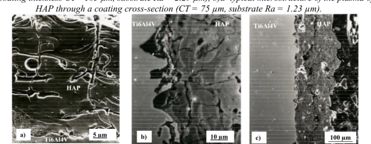
Figure 1:SEM micrographs showing: a) a typical top view of an HAP coating surface produced by air plasma spraying (coating thickness CT= 105 µm, substrate Ra = 2.29 µm), b)a typical microstructure of the plasma-sprayed
HAP through a coating cross-section (CT = 75 µm, substrate Ra = 1.23 µm).
Ti6Al4V HAP a) 5 µm Ti6Al4V HAP 10 µm b) HAP Ti6Al4V 100 µm c)
Figure 2: HAP coating cross sections showing: a) large perpendicular cracks emerging at the top surface (CT = 50 µm, substrate Ra = 1.23 µm), b) fine perpendicular cracks (CT = 165 µm, substrate Ra = 2.29 µm), c) interfacial and
interlamellar cracks (CT = 150 µm, substrate Ra = 2.29 µm).
The lamellar microstructure arising from the accumulation of the well-flattened molten splats contains also partially melted particles and various cracks. Some of the cracks are normal and others are parallel to the coating/substrate interface. Two kinds of normal cracks can be detected: large ones that emerge and open on the top surface of coating in the molten areas (Fig. 2a) and fine ones localized near the coating/substrate interface (Fig. 2b). It must be mentioned that the density of fine normal cracks increases when thickness of the coating increases. The parallel cracks are either localized in the interfaces of melted splats (interlamellar cracks) or in the interface between the coating and the substrate (interfacial cracks). For coatings deposited on the substrate having the
higher arithmetic average roughness parameter, cracks propagating in the interface are always detected when thickness is above 105 µm (Fig. 2c) and a good interfacial bonding is obtained when thickness is less or equal to 90 µm. Coatings deposited on the substrate having the lower arithmetic average roughness parameter Ra generally show the worse bonding quality with an increasing
interfacial cracking propensity when thickness increases. It must be outlined that pores and cracks lower the coating mechanical performance on one hand but support the ingrowth of the tissue into the ceramic material on the other hand.
If the existence of pores can be related to entrapped gases, poorly melted particles and poor bonding between adjacent splats, cracking is the result of relaxation of the residual stresses developed in the ceramic coating during the deposition process [14-16, 18]. In this study, while the largest cracks normal to the coating/substrate interface are very probably the result of the relaxation of the residual tensile stresses [16], the parallel cracks are mainly promoted by in plane compressive stresses producing induced through-thickness tensile stresses [19, 20]. Finally, since the thermal expansion of HAP is above that of Ti-6Al-4V, the finest perpendicular cracks detected near the coating/substrate interface is thought to be the result of tensile stresses due to the thermal expansion mismatch. As mentioned by Yang et al. [20], the mechanism of residual stress generation and the impact of these residual stresses are so complicated that only few works are devoted to the quantitative prediction of the magnitude stress.
Scratch testing and Scanning Electron Microscopy observations. Whatever the substrate
roughness, scratch tracks are not quite straight because the lack of contact between stylus and coating especially at the beginning of the mechanical tests. Microscopic evaluation shows that this fact is a consequence of coating roughness rather than substrate one. For each test, different events as cracking, progressive stylus penetration or instantaneous fracture of coating are encountered when the load increases. At the beginning of the test (low applied loads), a distribution of short cracks are detected in addition to the lack of contact between stylus and coating. When applied load increases, cracks become longer, the contact between stylus and coating becomes full and new features due to stylus crossing over pores are found.
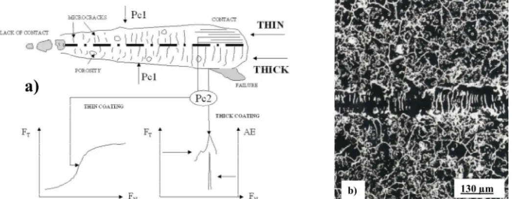
a)
130 µm b)
Figure 3: a) Synoptic of the events occurring on a typical scratch track under progressive loading and determination methodology of the critical loads for thick and thin coatings. Pc1: ormal load at which a microcrack reaches 50 % of
the scratch track width. Pc2: ormal load (F ) corresponding either to the inflexion point of the frictional force (FT)
graph for thin coating or to a sharp pulse on the acoustic emission signal (AE) combined with a sudden decrease of the frictional force for a thick coating, b) Example of microcracks formed during the scratch test in the range of applied
loads near the Pc1 value. This top view is related to the part of the graph indicated in Fig. 4.
An instantaneous adhesive spalling observed by visual inspection occurs generally before the contact between stylus and substrate, mainly in thick coating at high loads. This instantaneous spalling arises probably from the lateral crack propagation in the coating/substrate interface. On the other hand, for thin coatings, stylus can reach the substrate at intermediate loads without any instantaneous coating spalling ahead of the moving stylus. All these events are summarized on a synoptic of a typical scratch track in Fig. 3a. This figure presents also schematically how critical loads Pc1 and Pc2 were approximately determined.
Determination of the critical load Pc1 for crack initiation was delicate. In fact, it is impossible to
estimate directly and thoroughly Pc1 considering only the graph of the frictional force or the graph of
the acoustic emission because no significant change in these curves is observed (Fig. 4). Indeed, the frictional force does not change significantly for this critical load since cracks are produced behind stylus according to the Hertz theory [9]. As to the acoustic emission, microcracks initiating at Pc1
produce only short single peaks hidden in the noisy background. The critical load Pc1 was finally
determined from numerous and attentive scanning electron microscopy observations of all coatings. These observations based on a comparative study of crack length revealed that the normal load value, for which a microcrack reaches a length of 50% of the scratch track width, may be a satisfactory criterion to evaluate Pc1. An example of the microcracks formed in a range of applied
loads near the Pc1 value is presented on Fig. 3b.
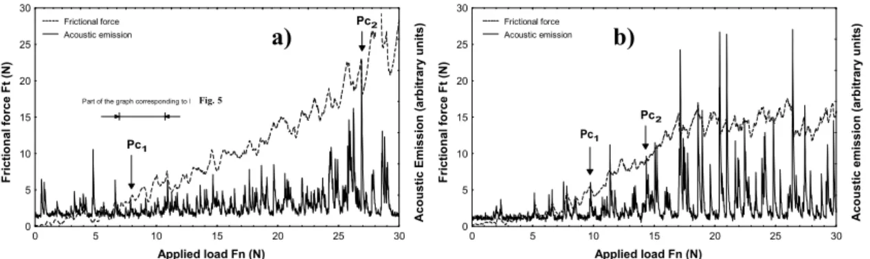
Applied load Fn (N) F ri c ti o n a l fo rc e F t (N ) A c o u s ti c E m is s io n ( a rb it ra ry u n it s ) 0 5 10 15 20 25 30 0 5 10 15 20 25 30 Frictional force Acoustic emission Pc2 Pc1
Part of the graph corresponding to Fig. 7Fig. 5
a) Applied load Fn (N) F ri c ti o n a l fo rc e F t (N ) A c o u s ti c e m is s io n ( a rb it ra ry u n it s ) 0 5 10 15 20 25 30 0 5 10 15 20 25 30 Frictional force Acoustic emission Pc2 Pc1 b)
Figure 4: Typical acoustic emission and frictional force variations during a scratch test in the case of: a) a thick coating (CT = 105 µm, substrate Ra = 1.23 µm), b) a thin coating (CT = 50 µm, substrate Ra = 1.23 µm).
Critical load Pc1 is plotted versus coating thickness in Fig. 5 for the two values of the arithmetic
average roughness of the substrate considered in this study. Whatever the substrate roughness, the mean of this lower critical load increases with thickness. This result can be explained taking into consideration the observed increasing propensity of microcracking that occurs during the cooling process when coating thickness increases. Since microcracking is considered to be the main relaxation process of residual stresses during cooling of plasma sprayed coatings, short cracks due to the scratch testing may be expected to initiate more easily in the studied thin coatings. Moreover, for a given coating thickness, Fig. 5 reveals a trend showing that the substrate having the higher arithmetic average roughness parameter induces a better coating resistance to microcrack initiation since the mean of the lower critical loads recorded are higher than that of the substrate having the lower arithmetic average roughness parameter.
Coating thickness (µm) L o w e r c ri ti c a l lo a d P c 1 ( N ) 2 4 6 8 10 12 14 16 50 60 90 105 135 150 165 325 Higher roughness Lower roughness a) Coating thickness (µm) H ig h e r c ri ti c a l lo a d P c 2 ( N ) 8 12 16 20 24 28 32 50 60 90 105 135 150 165 325 Higher roughness Lower rougnhess b)
Figure 5: Lower (Left) and higher (Right) critical loads Pc1 and the associated standard errors as a function of coating
thickness for the two studied substrate roughness. Results correspond to 5 and 8 measurements whatever the experimental conditions.
Generally used in comparative evaluation of adherence, the higher critical load Pc2 was estimated
in this study as the normal load which corresponds either to the instantaneous spalling of the coating or to the contact beginning between the stylus and the substrate. For thick coatings, the observation of instantaneous spalling can be correlated with the occurrence of intense peaks on acoustic
emission curves combined simultaneously with a local sharp decrease of the frictional force at high loads (Fig. 4a). However, secondary pulses especially on acoustic emission curves may prevent to find the true peak and hence to estimate precisely Pc2. The secondary pulses appear at high loads
and are mainly due to local coating failures that occur when the stylus interacts with pores or preexisting thermal cracks due to the plasma-spraying process. Sometimes, the stylus can cross over the largest defects associated with large and sharp discontinuities of surface topography resulting in significant sharp pulses on frictional force without significant effect on acoustic emission signal. The presence of such secondary pulses hampers the precise estimation of Pc2 directly from the
acoustic emission or the frictional force curves. This fact emphasizes the very usefulness of microscopic observations even if the lack of sufficient contrast of imaging between the coating and the substrate can be also an obstacle. In fact, the major problems encountered to estimate thoroughly
Pc2, due either to the interaction between stylus and initial flaws generated during the
plasma-spraying process in the coatings or to the lack of sufficient contrast of imaging, have been already mentioned by other authors [10, 12, 21].
Fig. 4b presents a typical graph of frictional force evolution and acoustic emission of a thin coating tested in this work. In this case, the higher critical load was assessed from microscopic observations and corresponds to the normal load for which the contact between the stylus and the substrate occurs. At first sight, it seems that the normal load value Pc2 determined by these
microscopic observations is not so far as the abscissa corresponding to the inflexion point on the frictional force graph. However, as mentioned by Stephanopoulos et al. [22], such a behavior is more representative of the interaction between the stylus and the substrate after the occurrence of contact rather than coating/substrate adhesion. As a consequence, it can be suspected that our experimental conditions of scratching may be no longer probing to predict adhesion of the HAP coatings which thickness is less or equal to 90 µm.
Pc2 critical load values versus coating thickness are plotted in Fig. 5b for the two values of the
arithmetic average roughness of the substrate considered in this study. It must be noted that it was not possible to determine the higher critical load for some of the thick coatings because of the upper experimental device loading limit (30 ). The higher Pc2 values for specimens having the substrate
roughness Ra of 2.29 µm can be related to a better adherence. It must be outlined that the scratch test
do not allow to obtain an absolute measure of coating adhesion because numerous extrinsic and intrinsic parameters influence the testing results [12].
Conclusion
Many parameters corresponding to the testing conditions, coating/substrate interface and coating or substrate oneself play important roles on the determination of critical loads Pc1 and Pc2. Therefore it
is not simple to correlate scratch test data with coating/substrate adhesion energy and the higher critical load Pc2 must be used only as a comparative value to characterize the coating adhesion. This
study on HAP coatings emphasizes the interest in combining scratch testing with scanning electron microscopy observations. Indeed, such observations seems to be particularly more relevant than the evolution study of either the frictional force or the acoustic emission to estimate the lower critical load Pc1 provided a criterion on microcrack length is fixed (50% of the scratch track width).
Moreover, SEM observations give interesting informations on the significance of the higher critical load Pc2 and put the experimenter on his guard against an abusive use of this macroscopic
parameter. Indeed, for thin plasma-sprayed HAP coatings, the higher critical load may be more representative of the interaction between the stylus and the substrate after the occurrence of contact rather than coating adhesion.
In this work, scratch testing shows that a substrate roughness value of Ra = 2.29 µm is favorable
with respect to Ra = 1.23 µm. The highest mechanical resistance (characterized by the Pc2 values) is
obtained for a coating thickness of 90 µm, value below which the bonding quality between coating and substrate becomes excellent. Moreover, taking into account the biomedical aspects in HAP
prosthesis application, coating must be sufficiently thick because of HAP dissolution in the fluid environment [7]. Thus, a 90 µm coating thickness sprayed on a substrate having an arithmetic average roughness parameter Ra equal to 2.29 µm seems the best compromise between
microstructure, mechanical resistance and long term stability in the physiological medium for an orthopedic application.
Acknowledgments
The authors are pleased to acknowledge the CRITT Céramiques Fines de Maubeuge (France) for the elaboration of the plasma-sprayed coatings and Professor H. Migaud of the Centre Hospitalier Régional de Lille (France) for helpful discussions about the medical aspects of this work.
References
[1] H. Liang, B. Shi, A. Fairchild, T. Cale: Vac. 73 (2004), p. 317.
[2] I.S. Lee, H.E Kim, S.Y. Kim: Surf. Coat. Technol. 131 (2000), p. 181. [3] L. Fu, K.A. Khor, J.P. Lim: Surf. Coat. Technol. 140 (2001), p. 263.
[4] Z.S. Luo, F.Z. Cui, Q.L. Feng, H.D. Li, X.D. Zhu, M. Spector: Surf. Coat. Technol. 131 (2000), p. 192.
[6] T.N. Kim, Q.L. Feng, Z.S. Luo, F.Z. Cui, J.O. Kim: Surf. Coat. Technol. 99 (1998), p. 20. [7] W. Suchanek, M. Yoshimura: J. Mater. Res. 13 (1998), p. 94.
[8] A. Benhamghader, B. Farsadzadeh, D. Najjar, A. Iost: Biomedical Engineering 2006 (IFMBE Proceedings, Malaysia 2006).
[9] A. Darbeïda, J. Von Stebut: Tribologie et Ingénierie des Surfaces, (SIRPE, Paris, 1996). [10] J. Valli, U. Mäkelä, A. Matthews, V. Murawa: J. Vac. Sci. Technol. A3 (1985), p.2411. [11] A. Cavaleiro, M.T. Vieira: Mater. Sci. Eng. A140 (1991), p.631.
[12] S.J. Bull, D.S. Rickerby: Br. Ceram. Trans. 88 (1989), p. 177.
[13] C.Y. Yang, B.C. Wang, E. Chang, J.D. Wu: J. Mater. Sci. Mater. Med. 6 (1995), p. 249. [14] K.A. Khor, P. Cheang, Y. Wang: JOM 49 (1997), p. 51.
[15] P. Filip, R. Melicharek, A.C. Kneissl, K. Mazanec: Z. Mettallkd. 88 (1997), p. 131.
[16] E. Park, R.A. Condrate, D.T. Hoelzer, G.S. Fischman, J. Mater. Sci. Mater. Med. 9 (1998), p. 643.
[17] Y. Fu, A.W. Batchelor, Y. Wang, K.A. Khor: Wear 217 (1998), p. 132. [18] Y.C. Tsui, C. Doyle, T.W. Clyne: Biomaterials 19 (1998), p. 2015. [19] M. Levit, I. Grimberg, B.Z. Weiss: Mater. Sci. Eng. A206 (1996), p. 30. [20] Y.C. Yang, E. Chang: Biomaterials 22 (2001), p. 1827.
[21] A.J. Perry: Thin Solid Films 107 (1983), p. 167 and Thin Solid Films 78 (1981), p. 77.
[22] N. Stephanopoulos, V. Bellido-Gonzalez, B. Hopper, D.G. Teer: Tribologie et Ingénierie des
Surfaces, (SIRPE, Paris, 1996).