BlueCache: A Scalable Distributed Flash-based Key-Value
Store
by
Shuotao Xu
B.S., University of Illinois at Urbana-Champaign (2012)
Submitted to the Department of Electrical Engineering and Computer
Science
in partial fulfillment of the requirements for the degree of
Master of Science in Computer Science and Engineering
at the
MASSACHUSETTS INSTITUTE OF TECHNOLOGY
June 2016
© Massachusetts Institute of Technology 2016. All rights reserved.
Author . . . .
Department of Electrical Engineering and Computer Science
May 20, 2016
Certified by . . . .
Arvind
Johnson Professor of Computer Science and Engineering
Thesis Supervisor
Accepted by . . . .
Leslie Kolodziejski
Chair, Department Committee on Graduate Theses
BlueCache: A Scalable Distributed Flash-based Key-Value Store
by
Shuotao Xu
Submitted to the Department of Electrical Engineering and Computer Science on May 20, 2016, in partial fulfillment of the
requirements for the degree of
Master of Science in Computer Science and Engineering
Abstract
Low-latency and high-bandwidth access to a large amount of data is a key requirement for many web applications in data centers. To satisfy such a requirement, a distributed in-memory key-value store (KVS), such as memcached and Redis, is widely used as a caching layer to augment the slower persistent backend storage (e.g. disks) in data centers. DRAM-based KVS is fast key-value access, but it is difficult to further scale the memory pool size because of cost, power/thermal concerns and floor plan limits. Flash memory offers an alternative as KVS storage media with higher capacity per dollar and less power per byte. However, a flash-based KVS software running on an x86 server with commodity SSD can-not harness the full potential device performance of flash memory, because of overheads of the legacy storage I/O stack and relatively slow network in comparision with faster flash storage. In this work, we examine an architecture of a scalable distributed flash-based key-value store to overcome these limitations. BlueCache consists of low-power hardware accelerators which directly manage raw NAND flash chips and also provide near-storage network processing. We have constructed a BlueCache KVS cluster which achieve the full potential performance of flash chips, and whose throughput directly scales with the number of nodes. BlueCache is 3.8x faster and 25x lower power consumption than a flash-backed KVS software running on x86 servers. As a data-center caching solution, BlueCache be-comes a superior choice when the DRAM-based KVS has more than 7.7% misses due to limited capacity. BlueCache presents an attractive point in the cost-performance trade-off for data-center-scale key-value system.
Thesis Supervisor: Arvind
Acknowledgments
First and foremost, I would like to thank my advisor, Professor Arvind, for being a dedi-cated advisor and an inspiring teacher. It is his continuous encouragement and persistent support that made this thesis possible.
I would acknowledge everyone involved with BlueDBM, Sang-Woo Jun, Ming Liu, Dr. Sungjin Lee, Chanwoo Chung, Dr. Jamey Hicks and John Ankcorn for providing inspirations and technical knowledge throughout this project.
I would also thank everyone else in Arvind’s group, Dr. Muralidaran Vijayaraghavan, Sizhuo Zhang, Andy Wright, Joonwon Choi and Thomas Bourgeat, for their support and advice.
Last but not the least, I would thank my friends near and far for their moral support. I hold special gratitude for my family, especially my parents, for their continuous faith and unconditional support throughout this work.
Contents
1 Introduction 13
1.1 Background . . . 13
1.2 Contribution of this work . . . 15
1.3 Thesis outline . . . 16
2 Related Work 19 2.1 Improving performance of a single-node KVS . . . 19
2.2 Using NAND flash to extend KVS capacity . . . 21
3 System Architecture 23 3.1 Hybrid-memory Hash Table . . . 25
3.1.1 In-memory index table . . . 26
3.1.2 Hybrid Key-Value Storage . . . 28
3.2 BlueCache Network . . . 31
3.2.1 Client-BlueCache Network Engine . . . 32
3.2.2 Inter-BlueCache Network Engine . . . 33
3.3 KVS Protocol Engine . . . 35
4 Software Interface 37 5 Hardware Implemenation 39 5.1 Hardware Accelerators . . . 40
5.2 Software Interface . . . 41
5.4 Power Consumption . . . 42
6 Evaluation 45 6.1 Single-Node Performance . . . 45
6.1.1 Single-Node Performance on DRAM Store . . . 45
6.1.2 Single-Node Performance on Flash Store . . . 47
6.2 Multi-Node Performance . . . 49
7 Social Networking Benchmark 53 7.1 Experiment setup . . . 54
7.2 Experiment results . . . 56
List of Figures
3-1 BlueCache overall architecture . . . 24
3-2 BlueCache node architecture vs. x86 server architecture . . . 25
3-3 4-way in-memory index table . . . 27
3-4 Hybrid key-value storage architecture . . . 28
3-5 Log-structured flash store manager . . . 30
3-6 Client to BlueCache node communication . . . 33
3-7 Inter-BlueCache node communication . . . 35
4-1 BlueCache software . . . 38
5-1 BlueDBM Architecture . . . 40
5-2 A BlueDBM Storage Node . . . 41
6-1 Single-node SET/GET operation throughput on DRAM . . . 46
6-2 Single-node SET/GET operation latency on DRAM . . . 47
6-3 Single-node SET/GET operation throughput on Flash . . . 48
6-4 Single-node SET/GET operation latency on Flash . . . 49
6-5 Multi-node GET operation bandwidth. (a) single client, multiple Blue-Cache servers, (b) multiple clients, single Bluecache Server, (c) multiple clients, multiple BlueCache servers . . . 49
6-6 Multi-node GET operation latency on DRAM/Flash . . . 51
7-1 Throughtput of memcached for relative network latencies . . . 55
7-2 BG performance of memcached, BlueCache, Fatcache vs. Active User Counts . . . 56
7-3 BGBenchmark performance for different capacity miss rates, memcached and BlueCache are configured to have the same capacity of 15GB . . . 58 7-4 BGBenchmark performance for different coherence miss rates . . . 59
List of Tables
5.1 Host Virtex 7 resource usage . . . 42 5.2 BlueCache estimated power consumption vs. other KVS platforms . . . 43
Chapter 1
Introduction
1.1
Background
In our current "Big-Data" era, the Internet is generating a large volume of dataset stored on disks/SSDs in public/private cloud. Big-data applications such as eCommerce, interac-tive social networking, and on-line searching, need to quickly process a large amount of data from data-center storage to provide instant valuable information for end users. For example, in 2014, Google received over 4 million search queries per minute, and processed about 20 petabytes of information per day [20].
For a lot of web application, persistent back-end data storage (e.g. MySQL, HDFS) consisting of tens of thousands of x86 servers with petabytes of rotating disks or SSD, often cannot keep up with the rapid rate of incoming user requests. In data-center architecture, a middle layer of fast cache in the form of distributed in-memory key-value stores, like memcached [41] and Redis [2], is typically deployed to provide low-latency and high-bandwidth access of commonly used data.
Existing in-memory key-value stores are often software running on commodity x86 servers exposing a simple and lightweight key-value interface where key-value pairs are resident in DRAM. Internally, key-values pairs are stored in a hash-table on KVS server’s main memory, and external clients communicate with KVS servers over network via a sim-ple commands such as, SET, GET, and DELETE. The software typically performs two ma-jor steps to process a KVS query on a server: 1) network processing that decodes network
packets into the key-value operation, 2) hash-table accessing that hashes the query keys and performs relevant operations on key-value memory slots pointed by the hash index. These two steps exhibit strong a product-consumer dataflow relationship, and it is well established that by tightly coupling network processing and hash-table accessing, a in-memory KVS node can achieve up to 130 Million requests per second on a x86 server [35].
In a cache-augmented architecture by using main-memory KVSs, front-end web appli-cations can sustain a much higher data traffic rate with fast response time. Nevertheless, if an item is not found in the memory pool, a price is paid to get from back-end storage system, which is orders-of-magnitude slower than the in-memory fetch. Typically in a data center, the aggregate DRAM capacity is an order of magnitude smaller than the total size of disks, and it is infeasible for DRAM to accommodate the entire working set of a web ap-plication. Due to hardware cost, power/thermal concerns and floor plan limits, it is difficult to scale up the memory pool size by packing more DRAMs or servers into data centers. Because of this limitation, NAND flash has attracted a lot of attention as an alternative storage device, since it offers higher storage density, bigger capacity per dollar and lower power per byte.
Flash device manufacturers typically package NAND flash chips into solid state drives (SSD) as a swap-in replacement of hard disk drives (HDD). Within SSDs, vendors typically organize NAND flash chips into multiple parallel channels, and employs a flash translation layer (FTL) to hide flash characteristics to provide a traditional device drive view to the operating system.
Naively, one could use SSD as a simple swap device [47, 29] by mapping it into the virtual address space. However, the swap memory management of the existing OS kernel is not suitable for NAND flash because it could lead to excessive amount of read/write traffic, which not only wastes the I/O bandwidth but shortens the NAND lifetime. Better software solutions like Twitter’s Fatcache [51], Hybrid Memory [44], SSDAlloc [6], and FlashStore [15] expand DRAM capacity with NAND flash by log-structured writing to that better exploits flash characteristics. These solutions share the following common features: 1) They work as an object cache and manage resource allocation at object granularity which is much larger than a kernel page. 2) They leverage the fast random read speed of NAND
flash to achieve low latency object access. 3) They maintain an in-memory index for all objects to have cheap cache hit/miss checks and simple on-disk object storage manage-ment. 4) They organize NAND flash into a log-structured sequence of blocks to overcome NAND flash’s writing anomalies. In these system organizations, terabytes of SSD can be paired with 50 to 100 GB on a single server, which is able to scale up the DRAM-based key-value store 10-100 folds. Compared to alternatives that use NAND flash as a virtual memory swap device, they show a 3.7X reduction in read latency and achieve up to 5.3X improvement in operation throughput with 81% less write traffic [44].
However, key-value software running on SSDs like Fatcache [51] still does not harness the full potential performance of flash devices because of FTL. FTL is a complex piece of software which manages flash overwrite restrictions, bad blocks, garbage collection, and address mapping. The inner-workings of FTL are completely hidden by manufac-tures, and without explicit control over data layout, it is difficult for KVS to consistently exploit the maximum parallelism of flash chips. Moreover, this additional layer of flash management can add significant hardware resources (multi-core ARM controller with gi-gabytes of DRAM [3]), and it is needlessly complex for KVS, increasing manufacturing cost, adding extra latency. Another drawback of SSD-backed key-value store is the duplica-tion of funcduplica-tionality of FTL and KVS software. FTL already manages flash memory in its own log-structured techniques, and running a log-structured KVS on top of log-structured FTL wastes hardware resources and incurs extra I/Os which could lead to auxiliary writing amplification [52].
1.2
Contribution of this work
This work explores a new key-value store architecture with raw flash memory, hardware accelerators and storage-integrated network. The hardware accelerators directly manage NAND flash chips at raw device level in an KVS-aware manner, which fully exploits po-tential performance of flash memory. Near-storage network forms near-uniform latency access to a cluster of KVS nodes, which scales with the number of nodes. We have built such system, called BlueCache. In particular, BlueCache provides the following
capabil-ities: 1) A 20-node cluster with large enough flash storage to hold up to 20TB key-value pairs; 2) An hardware-accelerated hybrid key value store tiered on DRAM and flash which has application-specific flash management; 3) Near-uniform latency access into a network of key-value nodes that forms a global key-value store;
Our experiment results show the following:
• Bluecache’s acceleration of network processing and in-memory hash table access shows 10x speed-up over over the popular DRAM-based KVS, the stock memcached. • BlueCache’s KVS-aware device-level flash management is able to maintain the peak performance of raw flash chips, and shows 3.8x higher throughput and 1.5x lower latency than flash-based software, Fatcache[51].
• As a data center caching solution, BlueCache becomes a superior choice when DRAM-based key-value cache has more than 7.7% misses due to limited capacity, which requires reading the slower back-end storage. In terms of energy efficiency, Blue-Cache has 25x more bytes per watt than flashed-based x86 architecture and 76.6x over DRAM-based x86 architecture.
In summary, BlueCache presents an attractive point in the cost-performance trade-off for data-center-scale key-value store system.
As to be discussed in the related section, almost all the components of BlueCache has been explored by a lot of other work. Yet the solution as a whole is unique. The main contri-bution of this work is as follows: (1) Design and implementation of distributed flash-based hardware-accelerated key-value store. (2) Performance measurements that show the advan-tages of such key-value store over existing software key-value stores. (3) Advanadvan-tages of BlueCache as a data center cache using an interactive social networking benchmark called BG[7] with full set-up of front-end clients, middle-layer cache, and back-end persistent storage.
1.3
Thesis outline
The rest of the thesis is organized as follows: In Chapter 2 we explore some existing re-search related to our system. In Chapter 3 we describe the architecture of BlueCache, and
in Chapter 4 we describe the software library to access BlueCache hardware. In Chapter 5 we describe a hardware implementation of BlueCache, and show our results from the implementation in Section 6. Chapter 8 concludes the thesis.
Chapter 2
Related Work
In-memoryKVSs store key-value pairs in DRAM, which allows fast data look-ups. They provide simple hash-table-like operations, such as set, get and delete, which make them attractive building blocks in large-scale distributed systems. In-memory KVSs are often deployed as a caching layer of the backend database, and a key typically represents a query to the backend storage, with its value as the corresponding query result. A large amount of KVS nodes are often clustered together to provide a high-throughput large-capacity storage. For example, Facebook’s memcache KVS cluster [41] handles billions of requests per second and holds trillions of items to deliver rich experience for a billion user around the globe. KVS cluster is a critical part of data-center infrastructure, often serving as a large-volume high-performance caching layer for big Internet services. There are two aspects to evaluate the performance of such distributed KVS cluster. (1) First aspect is throughput, the number of key-value operations a KVS service can deliver to the clients for a given SLA. (2) Second aspect is the aggregate KVS capacity, since it directly affects the cache hit rate. Cache misses typically penalize clients to fetch data from slow back-end persistent storage.
2.1
Improving performance of a single-node KVS
To address the first aspect, a lot of research efforts have been focusing on improving the throughput of a single-node KVS, since there are typically no server-to-server
coordina-tion in the cluster. A past study [46] has found that more than 90% processing of mem-cached, the most widely used in-memory KVS, is spent on the TCP/IP network stack. Many x86-based optimizations [49, 23, 24, 40, 16, 27, 37, 35] have demonstrated order-of-magnitude of performance improvement by using advanced network technology. Jose et al. [23, 24] investigated the use of RDMA-based communication over InfinitiBand QDR network, which dramatically reduced KVS process latency to below 12𝜇s and enhance throughput to 1.8MRPS. Other researches [37, 35] improve KVS by using Intel’s DPDK technology [22] which enables a direct path between NIC and last level cache (LLC) of CPU cores processing KVS queries. Li et al. [35] have shown 120MRPS KVS throughput with 95th percentile latency of 96𝜇s. As of writing, this is the highest performance of a
single-node KVS platform in literature.
However, a past study [38] shows that traditional x86 CPU architecture is inefficient to run KVS. Since KVS processing requires little computation (networking, hashing and accessing key-value pairs), traditional super-scalar CPU core pipeline can be underuti-lized [38]. The last level data cache, which takes as much as half of the processor area, can be also ineffective [38] and waste a considerable amount of energy, due to the na-ture of random memory access and large working set of KVS. There are researches us-ing non-x86 commodity hardware to improve a sus-ingle-node KVS. Berezecki et al. [9] use a 64-core Tilera processor(TILEPro64) to run memcached, and show competitive per-formance(~0.335MRPS) with less power consumption. Heterogeneous CPU-GPU sys-tem [21] has also been explored, showing moving data between CPU and GPU is the bottleneck. These approaches offer less satisfactory improvements than x86-based opti-mization.
Enhancing KVS performance using specialized hardware is also being investigated actively, such as Field Programmable Gate Array (FPGA). Researches have offloaded parts [38, 31, 18] or the entirety [13, 10] of KVS onto FPGAs, and demonstrate com-pelling performance with great power efficiency. Xilinx’s work [10] is the KVS of the highest performance in this direction, and achieves up to 13.2MRPS by saturating one 10GbE bandwidth [10], with round-trip latency between 3.5𝜇s and 4.5𝜇s. It also demon-strates more than 10x energy efficiency compared with commodity servers running stock
memcached. Note that the FPGA-based solution performance [10] is limited by 10GbE link. And the best x86-based KVS solution [35] uses 12 10GbE links, and per 10GbE link performance is 10MRPS.
2.2
Using NAND flash to extend KVS capacity
The aforementioned solutions essentially all forms a RAMCloud [42], a shared memory system over high-speed network. As data sizes grows in applications, more RAM needs to be added to a KVS node, or more KVS nodes need to be added to the network, to provide enough capacity for high hit rate. Although RAMCloud-style key value systems provide scalable high-performance solutions, their high energy consumption, high price/area per GB to address the capacity aspect of KVSs. NAND-flash-based SSDs are gaining traction in data centers [48, 8, 39, 33, 45]. Although slower than DRAM, flash memory provides much larger storage density, lower power per GB and higher GB per dollar than DRAM. It is a vialable alternative for applications like KVS with large workloads that needs to maintain high hit rate for high performance [36, 15, 51, 17, 4, 44, 19].
To extend capacity of DRAM-based software, past work used NAND flash as a simple swap device [47, 30] by mapping it into the virtual address space. However, the swap memory management of the existing OS kernel is not suitable for NAND flash because it could lead to excessive amount of read/write traffic. NAND flash is undesirable for small random writes, since flash has limited erase cycles and an entire page has to to be erased before new data is appended. High write-traffic not only wastes the I/O bandwidth but shortens the NAND lifetime [6].
Some KVS systems [36, 15, 51, 17, 4, 44] try to solve high-write traffic issue by using flash as an object cache instead of a swap device. They augment DRAM with flash by writ-ing key-value pairs in a log-structured manner. Research in this direction has reduced write traffic to NAND flash by 81% [44], which implies 5.3x improvement in storage lifetime. Flash Store [15] is the best performing single-node flash-backed KVS in this category, achieving 57.2 KRPS.
flash by storing large values on SATA SSDs. The hardware approach is effective in case that it saturates a 10GbE link, but it under-utilizes SSD device read bandwidth at below 25%.
Some other work attempts to enhance flash-based system by reducing the overhead of flash translation layer (FTL) of SSD. FTL is typically employed inside SSDs by flash vendors, to emulate hard drives behaviors and to provide interoperability for existing soft-ware/hardware. On FTL usually runs complex flash management algorithms, to hide un-desirable flash characteristics [14]. However, FTL is isolated in the storage stack, and can be suboptimal for applications because it does not have access to application information. Modern SSD typically only achieves 41% to 51% of its theoretical writing bandwidth [43]. Studies, such as SDF [43], F2FS [32] and REDO [34], improve flash device by reduc-ing FTL overhead, but they did not explore benefits of runnreduc-ing application-specific flash management for systems such as KVS.
Chapter 3
System Architecture
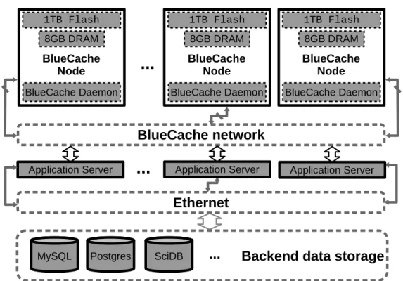
The BlueCache architecture is a homogeneous cluster of specialized hardware managing key-value pairs on raw flash chips (See Figure 3-1). Each BlueCache node has a maximum storage of 8GB DRAM and 1TB flash. On each BlueCache node runs a hardware daemon, which processes KVS protocols and manages key-value storage. The BlueCache daemon running on each node can communicate transparently to BlueCache daemon running on other nodes which are connected to by fast and low-latency specialized hardware network which we call BlueCache network. Web application servers are also connected to Blue-Cache network. Note that BlueBlue-Cache network is just an example of hardware-accelerated high-performance network, which does not have to the case for real KVS deployment. In real data centers, a BlueCache node can be connected via standard network such as 10Gbps Ethernet.
All BlueCache nodes shares a global view of the key value storage. To access Blue-Cache cluster, application server sends KVS queries to one of key-value service daemons, to check whether the result exists in the fast and low-latency cache. If it is a hit, data is returned from BlueCache hybrid memory. If it is a miss, application has to go back to the back-end persistent database via Ethernet, which is orders-of-magnitude slower than BlueCache. In our proposed organization, access to data not stored in BlueCache would be initially treated as a failure. Later, we would devise another layer of cache protocol to move data from back-end disks to flash in bulk.
BlueCache network
...
1TB Flash 8GB DRAM BlueCache Daemon BlueCache Node Application ServerEthernet
Backend data storage
MySQL Postgres SciDB
...
1TB Flash 8GB DRAM BlueCache Daemon BlueCache Node 1TB Flash 8GB DRAM BlueCache Daemon BlueCache Node
...
Application Server Application ServerFigure 3-1: BlueCache overall architecture
are accessed via the flash controller. Unlike SSDs which typically has embedded processors and DRAM to process complex flash management algorithms to support generic filesys-tems, the flash controller on BlueCache node provides a raw interface to the NAND chips at device level, which bypasses SSD proprietary firmware overhead. Only basic functions such as ECC and request reordering are implemented with the controller. Each hardware node also has access to 8GB of DDR3 memory on a single SODIMM slot.
A BlueCache node has three major hardware accelerators to process KVS queries (See Figure 3-2(a)). Hybrid-memory hash table is the centerpiece on a node, which manages key-value pair storage on both DRAM and flash in an effective manner. A network en-gine connects to other nodes and application servers, and distributes KVS queries to the corresponding nodes by linearly striping the global index space. The KVS protocol engine processes KVS requests and responses.
Figure 3-2 also compares the BlueCache node architecture with x86 server architecture. BlueCache node architecture is a group of tightly coupled hardware accelerators which has raw device-level controls over hardware components of DRAM, NAND flash, and network.
On the other hand, a x86-based architecture is essentially software running on CPU with main Memory, where the KVS software accesses SSD and network via operating systems and drivers across PCIe. In the first system organization, raw hardware components are transparent to hardware accelerators so that their maximum performance can be achieved. In the second system organization, flash, network and computation unit are connected via multiple hardware/software abstraction layers, which adds extra latency, hides raw hard-ware characteristics and results in sub-par performance.
NAND Chips DRAM Solid StateDrive
CPU
Network Interface (NIC)
Main Memory
PCIe
Block Device Driver NIC Driver Operating System PCIe KVS Software Network Interface Hybrid-memory Hash Table KVS Protocol Engine Network Engine
(a) BlueCache Node
(b) x86 Server node
Figure 3-2: BlueCache node architecture vs. x86 server architecture
In the following sections, we will describe the each components of a BlueCache node, the hybrid-memory hash table, network engine, and KVS protocol engine in order.
3.1
Hybrid-memory Hash Table
The BlueCache stores lookup information in a in-memory index table and actual key-value data on a hybrid key-value storage with DRAM and flash, which we call a hybrid-memory hash table. In the hybrid-memory hash table, the in-memory index table stores hashed keys instead of full keys to achieve high RAM efficiency and low false hit rate. The key-value storage is tiered on DRAM and flash, where hot entries are kept on DRAM, and less popular objects are stored on flash.
The hybrid-memory hash table exposes a set of three basic operations for data access. (1) SET(key, value) stores key value pairs on hash table and returns success/failure. (2) GET(key) looks up key in hash table, and returns the corresponding value if there is a matching record. (3) DELETE(key) deletes the key-pair on the storage.
3.1.1
In-memory index table
The addresses of the in-memory index table are calculated by applying Jenkins hash func-tion on the requested keys, which is also used in stock memcached for indexing hash table. Each index table entry only stores a hashed key instead of the entire key, along with other key-value pair metadata. Note that the hashed key is computed by a different hash function from Jenkins hash. In-memory index table only stores compact information of key-value pairs, to have efficient DRAM usage, as well as low false hit rate to avoid unnecessary key-value data read from flash.
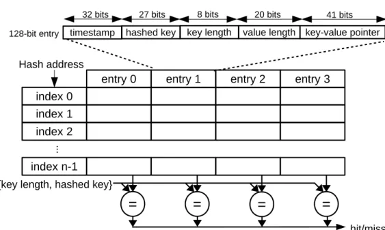
On software, programmers often use linked list, rehashing or other techniques to resolve hash collisions. However, with hardware accelerators there usually lacks a convenient and efficient memory management like CPU caches and prefetchers to support advanced data structures and computation. To implement a in-memory index table on hardware, we need to use different designing techniques from software. Since the DRAM controller issues a read request with a burst of eight 8-byte words, we assign each 64-byte aligned DRAM address to index a hash bucket. We use a modified set-associative cache design on CPU, to resolve hash address collisions at each hash address. The 64-byte data at each index is divided into 4 entries (Figure 3-3). Each entry is 128-bit wide, containing five fields: timestamp, a hashed key, key length, value length, and a pointer to the key-value pair.
When inserting a new entry at a index, an empty entry is detected by checking if the key length field is 0. If all four entries are taken, timestamps which record entrys’ latest access times, are compared and the entry with the oldest timestamp is evicted and overwritten by the new value.
When looking up a key-value pair in the in-memory index table, all four entries of a hash bucket are read. The key length and hashed key of each entry, which together form
an almost unique signature for an individual key, is checked in parallel to find a match. Note, the hashed key stored in entries is computed by a different hash function from the one used to index the table. If a match is found, key-value pair meta-data is returned (See Figure 3-3), which consists of a 20-bit value length field for a maximum 1MB object and a 41-bit key-value pointer, where 40 bits encode 1TB address space and 1 bit indicates whether object is on DRAM or flash. Full keys still need to be compared later to eliminate a false hit.
By storing only 128 bits(16 bytes) per in-memory index table entry, we can have 16x better RAM efficiency compared with storing full keys whose maximum size is 256 bytes. With 16 byte index entry, an index table consuming 8GB of memory can address 229(~half billion) key-value pairs on flash. If average object size is 2 KB, then an 8GB index can address 1 TB of flash storage. If average object size is 500 bytes, then an 8GB index can address 250GB of flash. Index size and key-value pair size are related this way to calculate the maximum addressable capacity of flash.
entry 0 entry 1 entry 2 entry 3
index 0 Hash address index 1 index 2 ... index n-1
=
=
=
{key length, hashed key}
hit/miss
key length
128-bit entry value length key-value pointer
41 bits 8 bits 20 bits
timestamp hashed key 32 bits 27 bits
=
3.1.2
Hybrid Key-Value Storage
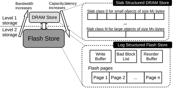
Hybrid key-value storage uses both DRAM and flash to store the objects that are referred by key-value pointers from in-memory index table. In particular, the key-value storage is partitioned among two levels of storages (See Figure 3-4). On level 1 Storage, commonly access objects are cached in DRAM, to have fast and high-throughput key-value response. On level 2 storage, less popular objects are kept on flash, to maintain a high hit rate with a large storage capacity. On level 1, DRAM store uses slab classes to store variable-length key-value pairs in a dense format. On level 2, flash store manages NAND flash chips in a log-structured manner. It appends small random writes on the DRAM write buffer before flushing to flash in bulk. When flushing buffered objects to flash, the flash store linearly stripes data on NAND chips on multiple channels to maximally exploit the device parallelism. DRAM Store
Flash Store
Bandwidth increases Capacity,latency increases Page 1 Page 2 ...Slab class 0 for small objects of size M0 bytes
Flash pages Reorder Buffer Bad Block List Write Buffer Page n Slab Structured DRAM Store
Slab class N for large objects of size MN bytes
... Level 1
storage
Log Structured Flash Store Level 2
storage
Figure 3-4: Hybrid key-value storage architecture
Slab-Structured DRAM store: On DRAM, key-value pairs are kept in slab-structured manner (Figure 3-4). Each slab is dedicated to store objects of predetermined size, and an object is kept in a slab class that is closed to its size. The advantages of such storage scheme are (1) simple logic which is feasible to implement on hardware, (2) flexibility to handle variable object sizes and (3) dense format allowing better RAM efficiency. Each slot
on a slab class stores object data, a timestamp and a back-trace pointer to its corresponding entry in the in-memory index table. When all the slots on a slab class are occupied, an old slot must be evicted to write the new data. A pseudo-LRU replacement policy is used, which randomly reads four slots on the depleted slab class and evicts the slot with the oldest timestamp to flash. After being evicted to a lower-level storage, the in-memory index entry must also reflect the change. The back-tracing pointer is used to update index table entry with a new address on flash. By using the pseudo-LRU eviction policy, the less popular entries are evicted to flash, and hot entries are kept on DRAM for fast access.
Log-Structured Flash Store: BlueCache devises lightweight flash management to ef-fciently use NAND chips, which supports KVS in a minimalistic manner. The entire flash store management is a RTL design implemented in hardware, adding minimal latency on top of raw NAND chip access. We uses log-structured flash management for BlueCache’s flash store, because flash chips are undesirable for small random writes as an entire page has to be overwritten whenever a new data is appended. The log-structured storage manage-ment efficiently handle small random write artifact by buffering written objects in DRAM and flushing data to flash in bulk. On BlueCache flash manager, there are three major components: a write buffer, a read order buffer and a bad block list (See Figure 3-4 and Figure 3-5). And they work together to provide complete functions for managing and ac-cessing key-value pairs on flash.
BlueCache flash store has two basic operations: For reads, pages storing key-value pairs are requested and read from the flash controller. The key-value pair is returned by calculating with the page offset and object size. If an object is split between multiple pages, the read reorder buffer coalesces pages of a key-value pair in the correct order, to deal with out-of-order responses from the flash controller. For writes, small data are appended to write buffers before writing to flash. As the buffer fills up, the content of the write buffer will be appended onto a new logic chuck on flash. A logic chunk on flash is a collection of pages which are uniformly mapped onto all physical NAND chips, as in Figure 3-5. In this way, BlueCache supports a perfect wear-leveling for maximum read parallelism, since data is evenly striped on all channels and chips. When a certain key-value pair is deleted, only its metadata is deleted from the in-memory lookup table, and the key-value data on flash is
simply ignored as stale.
On the background, the manager erases new blocks so that there are always fresh pages ready to be written. When an erase operation returns a bad block, its physical address is pushed into the bad block list to maintain a logic-to-physical block-level address mapping. BlueCache flash manager implements a minimalistic garbage collection algorithm. When flash space is depleted and the pointer to next empty chunk wraps around, an old flash chunk is simply erased and overwritten. The key-value pairs on a old chunk, whether valid or stale, are discarded. This still ensures KVS correctness, because a valid memory in-dex entry pointing to an erased key-value pair still produces a miss, since keys need to be compared to find a match. BlueCache’s garbage collection method is effective, since KVS workload typically has temporal locality and newly written data has higher popularity [5]. By overwriting oldest data, it is mostly likely that the KVS is replacing cold objects with hot ones. Furthermore, our flash management will not take data integrity issues such as power failure into consideration because it is used as a volatile key-value cache.
... Channel 0 ... Channel 1 Channel n-1 NAND Chip 0 ... appending
Chunk 0 Chunk 1 Chunk 2 Chunk 3 Chunk N-1 Write
Buffer 0 Buffer 1Write
Flash Logic View
Bad Block List Flash Physical View
DRAM NAND Flash
Write buffer ready to be flushed Victim chunk to be discarded and overwritten Chunk data is uniformly striped on all flash chips Write buffer/Chunk of 1MB Logical block ID Physical block ID NAND Chip 1 NAND Chip m-1 ... ...
3.2
BlueCache Network
BlueCache uses a fast and low-latency specialized hardware network that connects Blue-Cache nodes and client servers. In real data center deployment, a BlueBlue-Cache node can use standard network protocols and ports, such as TCP/IP over 10GbE, to make our system more compliant with data center network environment. Our implementation of BlueCache network is an example of accelerating KVS with near-storage network processing.
BlueCache has separate networks of inter-node communication and server-node com-munication. All BlueCache nodes are connected to a high-speed inter-controller network, which provides a uniform latency access to the KVS from any single nodes. A BlueCache node is pluggable onto the PCIe slot of an application server, and requests and responses are sent in DMA bursts. This particular network is feasible for a rack level deployment since the number of client servers is relatively small, and nodes are separated by short dis-tances to be chained together. But when there is more clients than BlueCache nodes, or scaling up to a data-center-sized cluster, a more generic switch-based standard network is more preferable.
In other in-memory KVS solution, like memcached, load balancing is usually done by clients by hashing the key and uniformly dividing keys to all KVS servers. Since Blue-Cache has a different network for node-node communication from client-node commu-nication, BlueCache network engine internally takes care of sharding the key-value pairs across the cluster, and a client can consult any BlueCache node to access any data on the KVS cluster. On BlueCache Cluster, a key is mapped to a node by
𝑛𝑜𝑑𝑒𝐼𝑑 = ℎ𝑎𝑠ℎ(𝑘𝑒𝑦) mod 𝑛𝑢𝑚𝑏𝑒𝑟_𝑜𝑓 _𝑛𝑜𝑑𝑒𝑠 (3.1)
In this way, keys are evenly sharded across the cluster, and the system maintains load balance. The hash function in Equation 3.1 should be a consistent hashing algorithm, so that when a node joins or leaves the cluster, minimal amount of key-value pairs needs to be reshuffled.
3.2.1
Client-BlueCache Network Engine
A BlueCache node is pluggable to a PCIe slot of a client server, and the client server can access the node via Client-BlueCache network engine. On Client-BlueCache network engine there are DMA read and write engines providing a direct DMA interface between the client and BlueCache node via PCIe. KVS protocol traffic are streamed between PC and hardware in DMA bursts, to maintain a high PCIe bandwidth.
To maximize the parallelism and maintain high performance, DMA read engine and DMA write engine are each mapped to a 1MB DRAM circular buffers on client PC, for writing requests and reading responses respectively. A DRAM circular buffer is divided into 128 smaller segments, with each segment for a bulk DMA transfer (See Figure 3-6). When sending KVS requests to BlueCache, the software circularly append KVS request protocols to free segment space on the DRAM request buffer. When a segment on the circular buffer is filled up with data, the client software sends DMA request to the DMA read engine with the segment index, and the hardware will start reading the data from the segment as DMA bursts. On the hardware side, request data is received in FIFO order. When the DMA read engine is done reading the segment, it acknowledges the software with the segment index, so that software pushes the segment index to a free segment list for future reuse. The KVS request protocol consists of a 24-byte request header and key-value data which is of variable length. Since KVS request protocols can be smaller and are misaligned with DRAM segments, a partially filled segment should be flushed to the hardware if there were no more incoming requests.
Similarly, when sending KVS responses, DMA write engine will circularly append response data to free segment space on DRAM response buffer on the client PC via DMA bursts. When the DMA write engine finishes sending an entire segment of data to client, the software on the client PC will receive an interrupt from the hardware with a segment index, and software can start parsing the KVS response protocol and reading the key-value data. After software consumes a segment, it acknowledges the DMA write engine with the segment index, so that the hardware can reuse the segment for sending new KVS responses.
DMA Read Engine Buffer 0 Buffer 1 Buffer 127 ... ci rc u la r a p p e n d KVS Requests Buffer 127 Buffer 1 Buffer 0 ...
DMA Write Engine
KVS Responses
...
...
DRAM Request Buffer DRAM Response Buffer
DMA data DMA req/ack
DMA data DMA interrupt/ack
Client-BlueCache Network Engine Valid response Valid request Client BlueCache ci rc u la r a p p e n d PCIe
Figure 3-6: Client to BlueCache node communication
3.2.2
Inter-BlueCache Network Engine
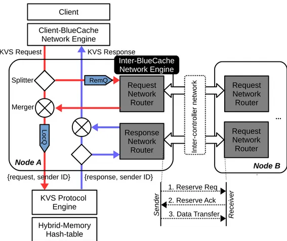
All BlueCache nodes are connected together via a low-latency high-bandwidth inter-controller network. Each BlueCache node is assigned with a unique node ID, and key space is uni-formly partitioned across all BlueCache nodes. Nodes can access all the partitions, and they share global view of the entire KVS. As shown in Figure 3-7, a BlueCache node trans-parently communicates with remote nodes via Inter-BlueCache Network Engine.
The Inter-BlueCache network engine splits/merges remote and local requests/responses onto protocol engine and Client-BlueCache network engine. As shown in Figure 3-7, to route KVS requests, after Inter-BlueCache network engine on Node A receives a KVS quest from Client-BlueCache network engine, it computes destination node ID of the re-quest with Equation 3.1. Depending on the destination node ID, the Inter-BlueCache net-work engine forwards the KVS request to either the remote request queue or the local request queue. In the former case, request network router on Node A sends the remote KVS request to the destination which is Node B. On Node B, the KVS request is received
by the network router, and is merged into the local request queue. All the KVS requests on the local request queue are tagged with their sender’s node IDs, and they are parsed by the KVS protocol engine and processed in the hybrid-memory hash table locally.
Likewise, to route KVS responses, after KVS reponses are returned from KVS protocol engine/hybrid-memory hash table, they are split to either local response queue or remote response queue depending on their sender’s node IDs. As in Figure 3-7, the response network router on Node B sends the remote KVS response which is requested from Node A. And the network router on Node A receives the KVS response, which is merged with local KVS responses. All local/remote the responses are returned to client via Client-BlueCache network engine.
Since our BlueCache prototype is aimed at a rack level deployment where each nodes are separated by short distances, we assume a lossless network between the nodes. For simplicity, BlueCache nodes are connected with a linear array network topology (average 0.5𝜇s/hop), but a better topology (e.g. star or mesh) is possible to enable higher cross-sectional network bandwidth or few number of network hops between nodes. BlueCache network uses multigigabit transceivers(MGT) which provides massive bandwidth and ex-tremely low latency. On top of MGTs builds the network transport layer which provides parameterizable independent virtual channels with a token-base end-to-end flow control and packet switched routing [26]. With the support of virtual channels, BlueCache network routers use a simple handshake network protocol between the sender and receiver (See Fig-ure 3-7). Before sending a payload, the sender sends a reserve request to the receiver with the size of the payload. The receiver reserves the memory for the incoming payload, and acknowledges the sender. After receiving the acknowledgment, the sender sends the pay-load data. Our handshake network protocol has an overhead equals 1.5𝜇s times number hops between sender and receiver. For a 10-node system, the maximum overhead is 15𝜇s, which is still relatively smaller than flash read latency(~100𝜇s).
Request Network Router
KVS Request KVS Response Splitter Merger Inter-BlueCache Network Engine KVS Protocol Engine Client Client-BlueCache Network Engine Response Network Router Hybrid-Memory Hash-table Request Network Router RemQ Lo cQ RequestNetwork Router 1. Reserve Req 2. Reserve Ack 3. Data Transfer S en de r R ec e iv er ... In te r-co nt ro lle r n et w or k Node A Node B
{request, sender ID} {response, sender ID}
Figure 3-7: Inter-BlueCache node communication
3.3
KVS Protocol Engine
The KVS protocol engine decodes KVS requests and formats KVS responses. BlueCache uses memcached binary protocol[50]. Each request/response has a 24-byte header and a payload. The KVS protocol header consists of fields such as request type(SET, GET, DELETE), payload metadata(key length and value length), and other fields such as opaque used for KVS request ID. The KVS protocol payload is simply key-value data.
On BlueCache, hybrid-memory hashtable together with inter-node routers produces a out-of-order response behavior. Since request key and response key need to be the same to produce a cache hit (Section 3.1.1), a completion buffer is needed to keep track of on-flight the request metadata. After a KVS request is decoded by the KVS protocol engine, it asks for a free entry index on the completion buffer, and request metadata is stored into the free entry slot. Then, the KVS protocol engine issues request along with its entry
index, to the hybrid-memory hash table. The hash table processes the request and returns response with corresponding completion entry index. If the response is a hash-table read hit, corresponding request metadata is read from the completion buffer, and request key and response key are compared to determine a cache hit. After the comparison, the KVS protocol engine formats the KVS responses and the used completion entry index is returned into the free completion buffer index queue.
Chapter 4
Software Interface
BlueCache provides a software interface for application users to access the KVS cluster. To application users, BlueCache software interface provides three basic C++ APIs. BlueCache C++ APIs can be also accessed by other programming languages via their C wrappers, such as JAVA through Java Native Interface (JNI).
1 b o o l bluecache_set(c h a r* key , c h a r* value , size_t key_length , size_t value_length ) ;
2 v o i d bluecache_get(c h a r* key , size_t key_length , c h a r** value , size_t* value_length ) ;
3 b o o l bluecache_delete(c h a r* key , size_t key_length ) ;
The APIs provide GET, SET and DELETE operations on the BlueCache cluster and their meanings are self-explanatory. These APIs are synchronous functions. In order to maxi-mize the parallelism, multiple client threads can concurrently access BlueCache cluster to exploit the full performance potential of the KVS appliance. The performance increases as more concurrent threads are spun by the clients, and it stops scaling beyond 128 threads.
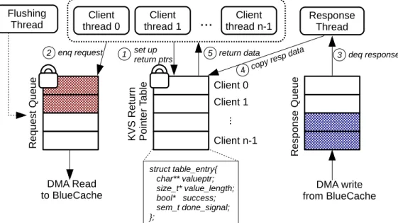
BlueCache software has three types of threads (See Figure 4-1) that are core to the concurrent processing of KVS requests. Client threads are the KVS users who access BlueCache KVS cluster via the software APIs. Flushing thread is a background thread that pushes partially filled DMA request buffers to hardware via DMA bursts, if there were no more incoming requests for a period of time. Response thread handles DMA interrupts from hardware, decodes response, and properly returns response data to clients. Moreover, BlueCache software also has three important data structures. A request queue maintains all
KVS requests that are ready to be read by hardware, and it is shared among client threads and the flushing thread. A response queue maintains all KVS responses returned from hardware, which is solely read by the response thread. A KVS return pointer table records the return data structure pointers for each client, so out-of-order responses can be returned to the correct client. This table is shared among client threads and response threads. All the shared data structures are protected by locks to guarantee atomic operations.
Client thread 0 Client thread 1 Client thread n-1
...
ResponseThread Flushing Thread R e q u e st Q u e u e K V S R e tu rn P o in te r Ta b le R e sp o n se Q u e u e Client 0 Client 1 Client n-1 .. . DMA Readto BlueCache from BlueCacheDMA write
struct table_entry{ char** valueptr; size_t* value_length; bool* success; sem_t done_signal; }; set up return ptrs 1 enq request 2 3 deq response copy resp data 4 return data 5
Figure 4-1: BlueCache software
Figure 4-1 also illustrates how the software accesses BlueCache KVS. When a client thread calls one of the three APIs, it first sets up in the KVS return pointer table. The KVS return pointer table has one entry for each client, and each client maintains pointers of return data structures on its own table entry. Second, the client thread push the KVS request to the request queue, which is later send to BlueCache via DMA. The client thread then sleeps and waits for the response. After BlueCache hardware finishes processing the KVS request and writing response data on the response queue, the response thread will receive an interrupt from the hardware and dequeue the response data. Then the response thread copies the response data to the return data structure by referring to the KVS return pointer table. After response data is copied, client thread is waken up and key-value access is completed.
Chapter 5
Hardware Implemenation
We used a Field Programmable Gate Array (FPGA) to implement the BlueCache hardware daemon which includes the hybrid-memory hash-table, the network engine and the KVS protocol engine. Development of BlueCache was done in the high-level hardware descrip-tion language, Bluespec [1]. Bluespec specifies hardware components as atomic rules of transition states, The Bluespec compiler can synthesize hardware specs the into circuits (i.e. Verilog) with competitive performance. Bluespec is also highly parameterizable and has a strong support for interfaces between hardware modules, which makes development of complex digital systems, such as BlueCache, a much easier effort.
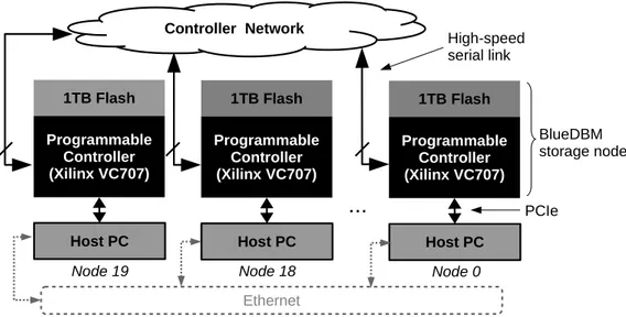
BlueCache is implemented on BlueDBM [25], a sandbox for exploring flash-based dis-tributed storage systems and near-data hardware accelerators. The platform is a rack of 20 Intel Xeon computer nodes, each with a BlueDBM storage node plugged into a PCIe slot. Each BlueDBM node storage consists of a Xilinx VC707 FPGA development board with two custom flash cards each plugged into a standard FPGA Mezzanine Card (FMC) port. Each BlueDBM storage node has 8 high-speed serial ports that can be used to directly con-nect the devices together and form a sideband network. Figure 5-1 depicts the architecture of a BlueDBM cluster.
We chose BlueDBM platform to implement BlueCache because it allows us to explore the benefits of (1) a large-capacity flash-backed KVS which has low-level raw access to NAND flash chips and application-specific flash management, and 2) acceleration of KVS by tightly integrating KVS processing with network. Note that BlueCache uses BlueDBM’s
Controller Network 1TB Flash Programmable Controller (Xilinx VC707) Host PC
...
1TB Flash Programmable Controller (Xilinx VC707) Host PC 1TB Flash Programmable Controller (Xilinx VC707) Host PC EthernetNode 19 Node 18 Node 0
PCIe High-speed serial link
BlueDBM storage node
Figure 5-1: BlueDBM Architecture
network infrastructure which is PCIe and inter-controller network, but for data-center de-ployment, BlueCache can take advantage of the 10GbE over SFP+ on the VC707 to have a more scalable and more data-center compliant network infrastructure.
5.1
Hardware Accelerators
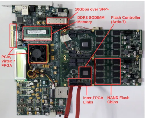
The BlueCache hardware accelerators are implemented on top BlueDBM storage nodes. Figure 5-2 shows a photo of a BlueDBM storage node hardware, highlighting the im-portant components for BlueCache’s implementation. Each BlueDBM storage node is a Xilinx VC707 FPGA development board attached with two custom flash card of 1TB ca-pacity. The VC707 board is the primary carrier card, and it has a Virtex-7 FPGA on which we implement hardware accelerators including hybrid-memory hash-table, network engine and KVS protocol engine. The hardware accelerators have direct access to hardware com-ponents on VC707: 1) a x8 PCIe gen 2 offering 4GB/s bidirectional link to the application server, and 2) one DDR3 SODIMM supporting up to 8GB of DRAM (1GB in our pro-totype), storing in-memory index table and DRAM store. The hardware accelerators also have access to two custom flash cards which are plugged into its FPGA’s FMC port. They communicate with the flash cards using GTP multigigabit serial transceivers pinned out
PCIe, Virtex 7 FPGA Inter-FPGA Links NAND Flash Chips Flash Controller (Artix-7) DDR3 SODIMM Memory 10Gbps over SFP+
Figure 5-2: A BlueDBM Storage Node
to the FMC connector. Each flash card has an array of 0.5TB flash chips organized into 8 buses, where resides log-structured flash store. On the flash card there is a Artix-7 FPGA as the flash controller which provides error-free chip-level access into the NAND array. Each flash card works independently, and offers 1.2GB/s bandwidth with typical 75𝜇s latency for read and 1300𝜇s for writes. Each flash card also has 4 high-speed MGT serial ports, and two cards provides 8x10Gbps links with latency of ~0.5𝜇s/hops for the inter-BlueCache network. The 10GbE over SFP+ on VC707 is not used in our prototype implementation.
5.2
Software Interface
We used Ubuntu 12.04 with Linux 3.13.0 kernel to implement BlueCache’s software in-terface. We used the Connectal [28] hardware-software codesign library which provides RPC-like interfaces and DMA over PCIe. We used a Connectal version which supports PCIe gen 1 with 1.6 GB/s writes to host DRAM and 1 GB/s reads from host DRAM, since
we only used one flash card in our experiment prototype and it meets the bandwidth re-quirement.
5.3
FPGA Resource Utilization
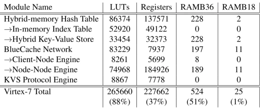
The FPGA resource usage of the Virtex 7 FPGA chip on the VC707 board is shown in Table 5.1. As shown in the table, BlueCache is a complex RTL design which uses the majority (88%) of the LUTs even on one of the biggest FPGA devices. In the BlueCache implementation, in-memory index table and node-node network engine take most signifi-cant amount of FPGA LUTs resources. The implementation also uses BRAM heavily as reordering buffers for the flash store and the network.
Module Name LUTs Registers RAMB36 RAMB18
Hybrid-memory Hash Table 86374 137571 228 2
→In-memory Index Table 52920 49122 0 0
→Hybrid Key-Value Store 33454 32373 228 2
BlueCache Network 83229 7937 197 11 →Client-Node Engine 8261 5699 8 0 →Node-Node Engine 74968 184926 189 11 KVS Protocol Engine 8867 7778 0 0 Virtex-7 Total 265660 227662 524 25 (88%) (37%) (51%) (1%)
Table 5.1: Host Virtex 7 resource usage
5.4
Power Consumption
Table 5.2 compares the power consumption of BlueCache with other KVS systems. Thanks to the lower consumption of FPGAs, one BlueCache node only consumes approximately 40 Watts at peak. A 20-node BlueCache cluster consumes 20,000 Watts and provides 20TB of key-value capacity. Compared to other top KVS platforms in literature, BlueCache has the highest capacity per watt, which is at least 25x better than x86 Xeon server platforms, and 2.5x more efficient FPGA attached with commodity SATA SSDs.
Platforms Capacity Power Capacity/Watt
(GB) (Watt) (GB/Watt)
FPGA with customized flash(BlueCache) 20,000 800 25.0
FPGA with SATA SSD(memcached) [11] 272 27.2 10.0
Xeon Server(FlashStore) [15] 80 83.5 1.0
Xeon Server(optimized MICA) [35] 128 399.2 0.3
Chapter 6
Evaluation
This chapter evaluates the performance characteristics of the BlueCache implementation.
6.1
Single-Node Performance
We evaluated GET and SET operation performance on a single BlueCache node. We mea-sured both throughput and latency of the operations. For peak throughput measurement, the software sends non-blocking requests to BlueCache hardware, with another thread parsing responses from the hardware. For latency measurement of operations, we send blocking requests to the hardware BlueCache hardware, and calculate average time difference be-tween each request and response. For measurement of GETs, the requests are random. All the measurements are performed on various sized key-value pairs on both DRAM store and flash store.
6.1.1
Single-Node Performance on DRAM Store
1) Operation Throughput: The throughput of SET/GET operations of BlueCache are mea-sured when all key-value pairs are stored on DRAM. Figure 6-1 shows SET/GET operation throughput vs. key-value pairs of different sizes. On DRAM, SET has peak performance of 4.14 Millions Reqs/Sec and GET has peak performance of 4.01 Millions Reqs/Sec. This is ~10x improvement over stock memcached(~410 Kilo Reqs/Sec at peak)
1 4 16 64 256 1024 4096 64 128 256 512 1K 2K 4K 8K 16K 32K 64K128K256K512K1M 0 0.5 1 1.5 2 Throughput (KRPS) Logscale Bandwidth (GB/s)
Key-value pair size in Bytes (a) SET Throughput
SET operation throughput Bandwidth 1 4 16 64 256 1024 4096 64 128 256 512 1K 2K 4K 8K 16K 32K 64K128K256K512K 1M 0 0.5 1 1.5 2 Throughput (KRPS) Logscale Bandwidth (GB/s)
Key-value pair size in Bytes (b) GET Throughput
GET operation throughput Bandwidth
Figure 6-1: Single-node SET/GET operation throughput on DRAM
As shown in Figure 6-1, when key-value pair sizes are small (<512B), operation through-put is bottlenecked by random access bandwidth of the DDR3 SODIMM memory on Blue-Cache. DRAM devices are great for sequential accesses, but sub-optimal for random ac-cesses. As measured from BlueCache’s DRAM device, bandwidth is 12.8GB/s for sequen-tial access vs 1.28GB/s for random access(10x slowdown). As the size of key-value pairs become larger, there are more sequential access pattern on DRAM than random, and Blue-Cache operation throughput is limited by the PCIe bandwidth. For large-sized key-value pairs, SET operation throughput (Figure 6-1a) is limited by 1.2GB/s PCIe reads from host server to BlueCache. And GET operation throughput (Figure 6-1b) is limited by 1.6GB/s PCIe writes from BlueCache to host server.
2) Operation Latency: The latency of SET/GET operations of BlueCache is measured when all key-value pairs are stored on DRAM. Figure 6-2 shows SET/GET operation la-tency vs. key-value pairs of different sizes.
The latency of a operation consists of PCIe latency, data transfer latency and other la-tency sources like DRAM lala-tency, BlueCache pipeline lala-tency and OS interrupt overhead. PCIe latency is constantly about 20𝜇s (10𝜇s each direction), and it is the dominant latency source when key-value pairs are small(<8KB). When key-value pair size grows larger, data transfer latency over PCIe becomes significant. Other latency sources becomes noticeable
0 200 400 600 800 1000 1200 1400 64 128 256 512 1K 2K 4K 8K 16K 32K 64K128K256K512K 1M Latency (us)
Key-value pair size in Bytes (a) SET Latency
PCIe Latency Data Transfer Latency Other Latency 0 100 200 300 400 500 600 700 800 64 128 256 512 1K 2K 4K 8K 16K 32K 64K128K256K512K 1M Latency (us)
Key-value pair size in Bytes (b) GET Latency
PCIe Latency Data Transfer Latency Other Latency
Figure 6-2: Single-node SET/GET operation latency on DRAM
yet still relatively small for big key-value pairs beyond 128KB. This is mostly due to la-tency caused by OS scheduling of more PCIe interrupts. The results from Figure 6-2 show that hardware raw device latency (PCIe latency and data transfer) is the dominant latency source of BlueCache key-value processing on DRAM store. And accelerating GET/SET operations on FPGA with DRAM (hashing, key-value lookup, etc.) adds a negligible la-tency to the overall processing time.
6.1.2
Single-Node Performance on Flash Store
1) Operation Throughput: The throughput of SET/GET operations of BlueCache are mea-sured when key-value pairs are stored on flash. Figure 6-1 shows SET/GET operation throughput vs. key-value pairs of different sizes. On flash, SET has peak performance of 6.45 Million Reqs/Sec and GET has peak performance of 148.49 Kilo Reqs/Sec.
The behavior of SET/GET operations are different on flash store than DRAM store. For SETs, key-value pairs are logged onto DRAM buffers before being bulk written to flash. As shown in Figure 6-3a, SET operation throughput is bottlenecked by NAND chip write bandwidth (~430MB/s), which is lower than the worst-case DRAM random write bandwidth.
0.25 1 4 16 64 256 1024 4096 64 128 256 512 1K 2K 4K 8K 16K 32K 64K128K256K512K1M 0 0.1 0.2 0.3 0.4 0.5 0.6 Throughput (KRPS) Logscale Bandwidth (GB/s)
Key-value pair size in Bytes (a) SET Throughput
SET operation throughput Bandwidth 1 2 4 8 16 32 64 128 256 512 64 128 256 512 1K 2K 4K 8K 16K 32K 64K128K256K512K 1M 0 0.2 0.4 0.6 0.8 1 1.2 1.4 Throughput (KRPS) Logscale Bandwidth (GB/s)
Key-value pair size in Bytes (a) GET Throughput
GET operation throughput Bandwidth
Figure 6-3: Single-node SET/GET operation throughput on Flash
For GETs, since reads from BlueCache’s flash device are in 8K page granularity, oper-ation throughput depends on the page read performance of NAND chips. As shown in Fig-ure 6-3, for key-value pairs smaller than 8K, pages fetched from flash have to be truncated, and the GET operation throughput is the flash page read throughput (~148K pages/sec). For key-value pairs that are multiple of pages, the GET operation throughput is limited by NAND random read bandwidth (~1.2GB/s)
2) Operation Latency: The latency of SET/GET operations of BlueCache is measured when key-value pairs are stored on flash. Figure 6-4 shows SET/GET operation latency vs. key-value pairs of different sizes.
The behavior of SET operation latency of flash store is similar to that of DRAM store (Section 6.1.1), since all the key-value pairs are logged onto DRAM buffered before being flushed to flash on the background.
For GET operations on flash store, there is ~75𝜇s flash read latency in addition to PCIe latency, data transfer, and other latency (OS scheduling, etc.). Unlike the DRAM store, PCIe latency (~20𝜇s) is comparably small, and flash read latency and data transfer become significant since NAND chips require transferring entire pages even for small reads. Other latency sources such as OS interrupt handling and BlueCache pipeline are relatively small. In conclusion, raw flash device latency is the dominant latency source of BlueCache
0 200 400 600 800 1000 1200 64 128 256 512 1K 2K 4K 8K 16K 32K 64K128K256K512K 1M Latency (us)
Key-value pair size in Bytes (a) SET Latency
PCIe Latency Data Transfer Latency Other Latency 0 200 400 600 800 1000 1200 64 128 256 512 1K 2K 4K 8K 16K 32K 64K128K256K512K 1M Latency (us)
Key-value pair size in Bytes (b) GET Latency
PCIe Latency Flash Read Latency Data Transfer Latency Other Latency
Figure 6-4: Single-node SET/GET operation latency on Flash
processing on flash store. And accelerating GET/SET operations on FPGA with flash adds a negligible latency to the overall key-value processing time.
6.2
Multi-Node Performance
0 50 100 150 200 250 1 2 3 4 0 0.5 1 1.5 2 Throughput (KRPS) Bandwidth (GB/s) Number of Clients (a) PCIe bandwidth 0 50 100 150 200 250 1 2 3 4 0 0.5 1 1.5 2 Throughput (KRPS) Bandwidth (GB/s) Number of Clients (b) Client[0] Client[1] Client[2] Client[3] 0 100 200 300 400 500 600 700 1 2 3 4 0 1 2 3 4 5 Throughput (KRPS) Bandwidth (GB/s) Number of Clients (c) Client[0] Client[1] Client[2] Client[3] Total Internal Flash BWFigure 6-5: Multi-node GET operation bandwidth. (a) single client, multiple BlueCache servers, (b) multiple clients, single Bluecache Server, (c) multiple clients, multiple Blue-Cache servers
Multi-Node performance is measured by chaining four BlueCache nodes together in a linear array. Each BlueCache node is attached to a client host server via PCIe.
follow-ing scenarios: (1) a sfollow-ingle client accessfollow-ing multiple BlueCache servers (Figure 6-5a). (2) multiple clients accessing a single BlueCache server (Figure 6-5b). (3) multiple servers accessing multiple BlueCache servers (Figure 6-5c). All accesses are 40,000 random GET operations of 8KB key-value pairs on flash store.
The first scenario examines the scalability of BlueCache KVS cluster when there is only one client. In Figure 6-5a, we observed some speed-up (from 148 KPRS to 200 KRPS) by accessing multiple BlueCache servers in parallel, but ultimately we are bottlenecked by PCIe (current x8 Gen 1.0 at 1.6GB/s). We are currently upgrading BlueCache pipeline for PCIe Gen 2.0, which would double the bandwidth. In general, since the total throughput from multiple BlueCache servers is extremely high, a single client connection interface cannot consume the aggregate internal bandwidth of a BlueCache KVS cluster.
The second scenarios examines behavior of BlueCache KVS cluster when there is a resource contention for the same BlueCache node. Figure 6-5b shows that the Inter-BlueCache network engine is biased to local node while maintaining the peak flash perfor-mance. Local node is allocated with half of flash bandwidth, and all the remote nodes fairly distributes the rest of half bandwidth. This is done because local nodes have relatively faster access to flash device, and priority is given to the operation that has the quickest response. The last scenario illustrates the aggregated bandwidth scalability of BlueCache KVS cluster, with multiple clients randomly accessing all KVS nodes. The line in Figure 6-5 shows the total maximum internal flash bandwidth of all BlueCache nodes, and the stacked bars shows overall throughput achieved by all clients. We achieved 99.4% of the maximum potential scaling for 2 nodes, 97.7% for 3 nodes, and 92.7% for 4 nodes at total of 550.16 KRPS. With even more nodes, we expect the serial-link network bandwidth becomes the bottleneck in this linked-list topology. However, we expect a more sophisticated network topology such as 3D mesh and good compression algorithm can help reach close to the total available internal bandwidth.
2) Operation Latency: Figure 6-6 shows the average GET operation latency for 8KB key-value pairs over multiple hops of the 4-node BlueCache KVS cluster. Latency is mea-sured from both DRAM store and flash store. Because of direct chip-to-chip links, the communication overhead of inter-BlueCache network is negligible. Our hardware counter
shows that each hop takes trivially ~0.5𝜇s, and inter-BlueCache network protocol takes 1.5𝜇s per hop. For DRAM store, we observed an ~2𝜇s increase of access latency/hop for various number of node traversals, which is miniature compared to overall access la-tency (~25𝜇s). Moreover, for flash store, the inter-BlueCache network lala-tency is virtually non-existent. In fact, the access variations (shown as error bars in Figure 6-6) from PCIe, DRAM and NAND flash are far greater than the network latency. This shows that the entire BlueCache KVS cluster can be accessed as fast as a local BlueCache node, even though it is physically distributed among different devices.
20 40 60 80 100 120 140 160 180 200 0 1 2 3 Latency (us) Number of Hops
Average GET latency on DRAM Average GET latency on Flash
24.15 26.05 30.92 31.05
155.93 156.37 153.87 158.24
Chapter 7
Social Networking Benchmark
We evaluate BlueCache against other caching solutions in data centers. Two comparison KVS we chose are memcached [41], a highly popular in-memory key-value cache, and Fatcache [51], a key-value cache with commodity SSDs, implemented by Twitter. Both systems are software running on commodity x86 servers.
To evaluate the three key-value stores, we set up an interactive social networking service (e.g. facebook.com, twitter.com) using BG [7] framework. BG is a benchmark that rates a data store for interactive social cloud service. It consists of a back-end data store of a fixed number of members each with a registered profile, and a front-end multi-threaded workload simulator with each thread simulating a sequence of members performing social actions. A social action presents an interactive activity by a member in the social network, examples being View Profile, List Friends, Post Comment, Delete Comment, and etc.
In our experiment configurations, the back-end data store of BG is a cache-augmented MySQL database. The MySQL database persistently stores member profiles in four tables with proper primary/foreign keys and secondary indexes to enable efficient database opera-tions. BG implements 11 social actions which can be translated to SQL statements to access the database. A particular key-value store of interest augments the MySQL database as the cache. BG uses social action type with the member ID as the key, and the corresponding social action results as the value. The average size of key-value pairs of BG benchmark is 1.54KB, with maximum size of 4.6KB. For read-only social actions, BG consults the MySQL database only if results fail being fetched from the key-value cache. For social