Assessment of Emerging Renewable Energy-based Cogeneration Systems
for nZEB Residential Buildings
Carolina Carmo#1, Olivier Dumont*2, Mads P. Nielsen#3, Brian Elmegaard°4
#Energy Technology Department, Aalborg University Pontoppidanstræde 101, 9220 Aalborg Ø, Denmark
1[email protected] 3[email protected]
*Thermodynamics Laboratory, Univ. Liège, Belgium
2[email protected] °DTU Mekanik, DTU, Lyngby, Denmark
4[email protected] Abstract
Net Zero Energy Buildings (nZEB) imply reduced consumption by means of good insulation, passive strategies and highly efficient energy supply systems. Among others, micro cogeneration systems are considered as one of the system solutions with the highest potential to enable nZEB. These systems entail production of electricity and usable thermal energy (heat and/or cooling) to cover the energy demands of residential buildings, high energy efficiency levels and proximity of the energy source to the building. The concept of cogeneration is not new but the interest in small scale cogeneration technologies based on renewable energy sources has increased tremendously in the last decade. A significant amount of experimental and modelling research has recently been presented on emerging technologies. In this paper, four main technologies are assessed: Fuel Cells (FC), Photovoltaic thermal (PV/T), solar thermal reversible heat pump /organic Rankine cycle (HP/ORC) and cogeneration solar Thermoelectric generators (TEG).
This paper aims to give an overview of the state-of-the-art developments, discuss the fundamental and technical challenges facing commercial adoption and prospects of these technologies for use in single-family houses. A schematic of each technology, a graph comparing the technical characteristics and a radar chart contrasting the strengths and weaknesses of each technology in market diffusion are provided.
Keywords - residential µ-CHP; Fuel cells; photovoltaic thermal; solar thermal HP/ORC; Thermoelectric generators
1. Introduction
The facts that buildings represent 40% of the world’s primary energy use [1] and that there are evidences of a two-way causality relation between renewable energy consumption and economic growth in both short-and long-run [2] has increasingly oriented research towards new building concepts focused on energy demands reduction and renewable energy based systems.
In this context, cogeneration “the process of producing both electricity and usable thermal energy (heat and/or cooling)” [3] , in particular, micro combined heat and power (µ-CHP) systems have proven to be superior to traditional systems, not only in terms of
greenhouse gas (GHG) emission reduction but also in total conversion efficiency [4]. The concept of µ-CHP is used to denote systems with an electric capacity smaller than 15kWe (according to EU directive 2004 the size is <50kWel).
These systems require careful integration of the building supply system. The building stock and structures in EU are dominated by residential buildings (75%), of which 64% are detached single-family houses [5]. Detailed data on the breakdown of end energy use in dwellings in EU-27 indicate that space heating represents on average 68% of the total energy use, while water heating, electricity for lighting and appliances and cooking represent 12%, 14% and 4%, respectively. However, the specific end-use energy demand can vary a lot. For example, space heating represents only 36% in southern countries like Cyprus and up to 74% in other countries like Austria and Latvia. The same happens with water heating varying from a minimum of 5% in Bulgaria and up to 27% in Spain; cooking with a min. of 2% in Finland and Denmark and a max. of 29% in Romania; and appliances with a min. of 5% in Estonia and a max. of 28% in Cyprus [6].
The operation strategies for CHP units can be: power-oriented, heat-oriented or cost-oriented depending on the supply building [4]. µ-CHP are usually heat-cost-oriented since heating represents the largest share of energy end-use in residential houses. A low heat output reduces the issue of thermal demand interfering with µ-CHP system operation, which is paramount for success of these technologies since electricity is often considered as a more noble form of energy, with higher economic value than heat.
Both demand and supply factors vary considerably across Europe. Thus, efforts to convert the energy supply in buildings vary and the renewable or non-renewable energy source choice is mainly driven by the local resources. Yet, the technology choice is not straight forward as it depends on several factors:
- Technical challenges, including specific end-use energy demand; - Social acceptance;
- Energy Market.
An increasing number of studies discuss the developments, energy-cost saving, environmental impact and social acceptance of µ-scale CHP systems for domestic applications. However, these focus mainly on combustion CHP systems and/or combustion hydrogen and oxygen fuelled systems [7, 8, 9, 10], i.e. mainly in non-renewable energy based technologies. In this paper, a review of the state-of-the-art of emerging of µ-CHP systems based on free energy sources and/or emission-free with reference is done. Their layouts are presented and systems performance discussed. Finally, the prospects in the residential sector are deliberated considering the three factors listed above.
The aim is to assess the feasibility of µ-CHP technologies introduced in the context of applicability in single-family houses. The framework is limited to the socio-technical challenges as well as market prospects by means of levelized cost of energy (LCOE).
2. Renewable energy based µ-CHP technologies: state-of-the-art
In the current stage, natural gas fuelled reciprocating engines are the most mature both in technological reliability and economic competitiveness. In 2012, they
represented 65% of the global market share of domestic µ-CHP systems [11]. In the transition to energy systems based on renewable sources, these systems will still play an important role as they are compatible with alternative fuels, for example biogas [4], but this study focus on emerging technologies that are available (or will be in the near future) in the market. They are in a range of Technology Readiness Level (TRL) of 8-9 [12], and they have an electric power output suitable for single family households.
2.1 Fuel Cells (FC)
After internal combustion engines, the most mature technology is terms of marked development is by far proton exchange membrane (PEM) fuel cells. They have seen their market rise from 4% to more than 5 times between 2009 and 2012 [11].
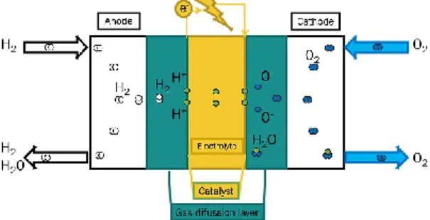
Fuel cells typically use hydrogen as fuel. It can be extracted from water or biogas, they emit almost none greenhouse gases (GHG) [4]. The only by-products of fuel cell systems are water vapour and excess heat (produced in the hydrogen reformer and fuel stack). Fuel cells generate an electrical unbalance due to the electrochemical reaction of reactants separated by an electrolyte membrane that only allows ions crossing. This unbalance generates electron motion, i.e. current. Fig. 1 shows the process and basic components of a fuel cell.
Fig. 1 Fuel cell stack components
There are different types of fuel cells traditionally named after the electrolyte material and with different designs depending on the application [13]. The operating temperature, which limits the heat usability, start-up time and ability to vary output, is often a significant factor to determine the type of fuel cell to be used. There is no limit on capacity due to their modular stack design nature. The most favoured type for domestic µ-CHP applications (also known as, stationary small systems) are low and high temperature proton exchange membrane (PEM or PEMFC and HTPEMFC, respectively) and high temperature Solid Oxide (SOFC), as they provide the highest power densities [14].
PEM consists of a solid polymeric membrane electrolyte, situated between electrodes and Platinum as catalyst. Their fuel stack operating temperature is typically between 70-110°C, while the reformer generates heat between 160-1000°C depending on the fuel. HTPEMFCs work at higher temperatures (160-180°C). These show better
resilience to fuel impurities and allow easier integration into existing heat distribution systems. But, lower life time which could be overcome with serial production [15].
SOFC are solid state power systems that typically use a ceramic material called yttria-stabilized zirconia (Y2O3ZrO2) as the electrolyte. Nickel is used as catalyst. Their
operating temperature is between 750-1000°C. SOFC have longer start-up and cooling phases than PEMFC which might affect cost of SOFC. But, they present lower capital costs, no need for expensive catalysts, as the reformation occurs in the anode, thus they can be directly fuelled by natural gas [16].
Under feasible operational premises, their electrical efficiency varies from 30-45% (PEMFC) and between 40-60% (SOFC) and the thermal efficiency between 35-60% and 25-30%, respectively [7, 13, 17]. They can produce the lowest heat to power ratio (HPR) of any CHP technology [17]. SOFCs have often the highest electrical efficiency than PEMFCs, however PEMFCs offer better which leads to better overall CHP efficiency and makes both technologies well suited for different domestic applications. Furthermore, FC systems present an excellent performance at partial load operation (constant and equal to full load efficiencies for partial loads >30%) [15]. This makes them quite flexible in terms of energy supply without compromising the overall system efficiency.
With respect to market development, FC manufacturers have beneficiated from a close collaboration with boilers manufacturers to ensure a broad market and end-user acceptability [4].
2.2 Photovoltaic thermal
Another type of environmental concern µ-CHP are PV/T collectors. It refers to a system that combines a PV module with conventional solar thermal collector in a single equipment. A PVT uses the solar radiation not converted into electric energy to produce thermal energy to improve the overall efficiency of the system and generate both electricity and heat. This hybrid solution enables an investment cost decrease up to 25% when compared to PV + solar thermal collectors side by side [18]. However, so far PVTs have not had a commercial breakthrough when compared to PV or solar thermal, mainly due to product reliability and initial costs [19].
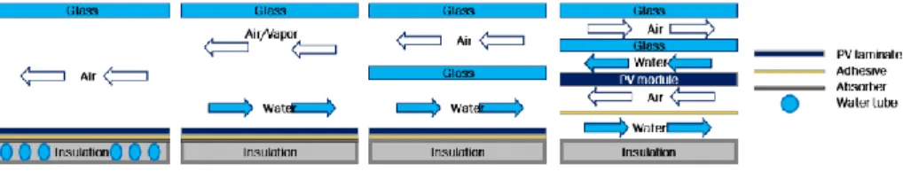
They can be classified by the type of heat transfer medium (air or liquid), the glazing configuration and the PV technology used [20]. This paper focuses on PVT modules with liquid heat transfer medium as they can provide the domestic hot water at higher efficiency levels and lower space requirements than air based systems due to poor air thermal transfer capabilities. Fig. 2 shows the covered types of PVT systems with liquid working fluid by glazing configuration type. Covered PVT systems have a larger heat output than uncovered, however the latter present larger electrical efficiency and are more popular [20].
Fig. 2 Sectional view of a typical photovoltaic flat plate collectors
The electrical efficiency of these systems, which depend mainly on the incoming solar irradiance (W/m2) and the PV module temperature, ranges from 13% to 28% and
the thermal efficiency, which depends on the solar irradiance (W/m2), fluid and ambient
temperatures (K) ranges from 50% to 77% [21].
2.3 Solar thermal heat pump/organic Rankine cycle (HP/ORC)
Over the last years, several studies and experiments have assessed and proven solar assisted heat pump systems for maximizing the exploitation of renewable energy sources [22]. More recently the possibility to invert the solar heat pump cycle to enable a Rankine cycle has been assessed. In such a system the scroll compressor of the solar heat pump system is modified to work as an expander when needed and a pump is added. This enables the system to supply both electrical power and heat. In 2011 [23], the first simulation model of such a system was introduced to assess its annual performance and three years later a prototype with refrigerant R-134a of such a system, known as an HP/ORC reversible unit, installed in an existing house in Denmark was presented [24].
Fig. 3 Solar HP/ORC system scheme on HP mode [24]
In micro scale CHP systems, organic working fluids are preferable because of their mechanical and thermodynamic characteristics at low temperatures (<473K). Although the specific investment cost can be as high as for a conventional steam cycle the operating cost is lower as the fluid mechanics allow higher turbine efficiency - in full and partial load (only a 8% efficiency decrease at 50% load –demonstrated in large scale – ORC power plant), lower pressures, thus smaller components than water based Rankine cycles [9].
Both heat pump and ORC systems have been used successfully for decades. The efficiency of these systems depend on the operating temperatures of the heat sink and source, therefore the maximum electrical efficiency of these systems for domestic
applications is rather low compared to the other technologies in this study. Experimentally, these systems are expected to have an electrical efficiency of 4.2% (with evaporation temperature (Tev) of 298K and condensation (Tcond) of 361K) and a
thermal coefficient of performance of 3.1 (Tev = 334K and Tcond =294K) in heat pump
mode and heating efficiency of 80% in direct solar heating.
Compared to the other technologies here investigated, the reversible unit presents a slight disadvantage regarding user-friendliness, noise and climate protection, the need of electricity from the grid or battery to drive the heat pump.
2.4 Thermoelectric generators (TEG)
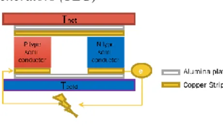
Fig. 4 Schematic diagram of TE module
The thermoelectric generators are pairs of p-type and n-type semiconductor materials, which generate electricity when a temperature difference is applied, also called the Seebeck effect (Fig. 4). Their most common application is thermal sensing (thermocouples) and waste heat recovery. The efficiency of these systems is proportional to the figure of merit (ZT) of the semiconductor materials. The figure of merit is a dimensionless number that measures the ability of the material to produce thermoelectric power. A high ZT indicates that the phonons –responsible for thermal conductivity – scatter, and electrons – maintaining the electrical conductivity- aggregate at a given applied temperature difference. Each semiconductor material present better or worse electrical conductivity at different temperature levels. For domestic applications, low temperature category (up to 473K), bismuth in combination with tellurium, Bismuth Telluride (Bi2Te3) the most common alloy. However, its electrical efficiency is still lower than any of the technologies above, below 5% at ΔT as high as 200K [25].
As PV systems, TEG are solid-state green technologies and despite their lower efficiency they are technically attractive due to their size, reliability, long maintenance-free period and compatibleness with both solar and non-solar heat sources.
Many efforts have been made in development of new materials based on the recently developed materials its efficiency could be enhanced up to 8.2% (ΔT=60K) [26].
3. Methods
a. Social-Technical challenges
First, based on the information compiled in the previous chapter, the feasibility of the systems for domestic applications is assessed based in electrical and thermal
efficiency, current investment costs (€/kWh) and subsequently, scrutinized against 6 key performance indicators reflecting end-user essential requirements.
The indicators, that gave the framework for assessing the social acceptance of the technologies studied, are based on previous surveys of residential CHP solutions success in the domestic market. These concluded that the aspects technologically enthusiastic citizens, also known as pioneers, find most important when thinking about their home energy supply are: reliability and energy efficiency, climate protection, low operation costs, user-friendliness and low maintenance [4, 27].
b. Market challenges
Subsequently, to pave the way for the market development of these technologies in the domestic environment, an analysis based on simple operation costs considerations is proposed. The levelized cost of energy (LCOE), in this case electricity, is calculated by adding up the investment, operation and maintenance costs with a real annual discount rate of 4% and compared to marginal purchase costs of electricity for households in Denmark [28].
The main hypotheses for the LCOE calculations are summarized below: For all the systems it is assumed that both electrical and thermal energy are
used to supply the house demands;
The heat demand limits the operation, i.e. the operation is heat-oriented. However, for TPV and TEG systems the annual energy output is calculated based on the product of the electrical capacity of the installation and the total bright sunshine hours in Denmark (1495h) [29]. While for FC systems, its energy output is calculated based on the total average number of hours in the heating season based on the standard EN14825 (4910 hours). Finally, in the case of a HP/ORC system the results of a simulation in a passive Danish house are used [30]. A thermal storage tank of 150-200 L is considered in all the investment costs;
The annual operation and maintenance costs for:
o TPV system are estimated 1% of the investment costs and assumed to increase at a rate of 1% per year of operation [31];
o FCs are estimated based in a comprehensive review made by IEA in 2005 for more than 25 FC manufactures all over the world [15]. For PEMFC the costs are estimated to be 0.030€/kWh while for SOFC are 0.021€/kWh. This costs vary with the FC size (kW). Furthermore, it is assumed a output power degradation of 2.5% for each 1000h of operation [13];
o HP/ORC are expected to be 5% of the initial investment [24]; o TEG systems are only the maintenance costs of solar collector in
Danish conditions [32, 33], no maintenance costs are expected for 20 years lifetime with regards to the thermoelectric device [26].
4. Results and Discussion
As explained earlier, µ-CHP are usually heat-oriented since heating represents the larger share of energy end-use in residential houses. However, the energy end-use share can vary a lot and different operation strategies are needed. Fig. 5 shows the wide variety of µ-CHP electrical and thermal conversion efficiencies and investment costs considered for the analyses carried out in this paper, one per technology. It puts in evidence the versatility of µ-CHP to match assorted domestic electric to thermal ratios.
Fig. 5 The representative electrical and thermal efficiency points of each technology. The blue lines show the total CHP efficiency at 50% and 100%
Moreover, in the current stage, the following conclusions can be drawn from the figures with regards to the µ-CHP unit considered in this paper:
They present high total energy conversion efficiencies higher than 60% fulfilling an important requirement of future buildings (Fig. 5);
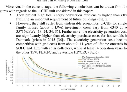
However, they still suffer from undesirable economics. µ-CHP for single-family houses (about 1 kWe) investment costs vary from 6340 up to 35715€/kWe [13, 24, 34, 35]. Furthermore, the electricity generation costs are significantly higher than electricity purchase costs for households in Denmark (prices in 2015 [36]). The electricity generation costs become competitive with grid costs from about 9 -11 years of lifetime onwards for SOFC and TEG with solar collectors, while at least 14 operation years for the other TPV, PEMFC and reversible HP/ORC (Fig.6).
Fig. 6 LCOE (without taxes) of the technologies considered in the study again system lifetime Fig. 7 compiles the results of the analysis of all technologies for domestic
applications. Higher scores on the parameters on left side reveal that, in general, the systems studied have a promising prospect with respect to
17500€/kWe
Elmer et al. (2015) 35715€/kWe
Elmer et al. (2015) 10000€/kWe Tripanagnostopoulos et al. (2005) 6340€/kWe Hi-z.com. (2015) 9000€/kWe Dumont et al. (2015)
domestic end-user requirements. The lower scores on the parameters on the right side reflect the economic weaknesses of each technology;
Fig. 7 Radar chart with results socio-technical acceptance performance of each technology A market research run in three European leading countries in terms of µ-CHP units sale in 2012 [37], concluded that end-users are willing to pay not more than approximately 3500€ to install new domestic energy supply systems which is still far from the current prices for the systems here considered. Yet, it is common to find successful incentives from governments (subsidies) and utilities (loans) to encourage the uptake of these systems [13, 38]. This indicates, that restructuring of markets, reorientation of business strategies and regulatory reforms are mandatory to encourage the uptake of µ-CHP systems. Likewise, changes in the regulatory framework will certainly trigger changes that will go beyond the cost orientation and improve the customer services.
Furthermore, the match between the unit energy outputs and the specific heat and electricity demand of the building are crucial to further improve the economic feasibility of µ-CHP systems. It is also obvious that appropriate sized system and integration of electrical and thermal energy storage, which have proven attractive lower costs recently [39], can generate larger operation costs benefits. The magnitude of these benefits is out of the scope of this study.
5. Conclusions
This study indicates that in the next years a trend for the usage of µ-CHP units based on renewable energy sources is expected to enable nZEB households. However, even if their energy savings, technical suitability and realization of end-users envision of their energy supply are undisputed, the economical obstacles will still remain and its diffusion will be insufficient if market and regulatory framework is not changed.
References
[1] IEA, „World Energy Outlook 2015,“ http://www.worldenergyoutlook.org/ [Accessed 12-01-16].
[2] Nicholas Apergis et al., „Renewable energy consumption and economic growth: Evidence from a panel of OECD countries,“ Energy Policy, vol. 38, pp. 656-660, 2010.
[3] W. A. f. D. Energy, „Guide to Decentralized Energy Technologies,“ Edinburgh, 2003.
[4] M. Phent et al., Micro Cogeneration: Towards decentralized energy systems, ISBN 10 3-540-25582-6, 2006. [5] M. E. et al., „Europe´s Buildings Under the Microscope,“ Building Performance Institute Europe (BPIE), 2011. [6] E. E. A. (EEA), May 2012. [Online]. Available:
[7] Dentice d'Accadia et al., „Micro-Combined Heat and Power in Residential and Light Commercial Applications,“ Applied Thermal Engineering, vol. 23, pp. 1247-1259, 2003.
[8] Mingxi Liu et al., „Combined cooling, heating and power systems: A survey,“ renewable and Sustainable Energy Reviews, vol. 35, č. http://dx.doi.org/10.1016/j.rser.2014.03.054, pp. 1-22, 2014.
[9] L. Dong et al., „Development of small- scale and micro-scale biomass-fuelled CHP systems - A literature review,“ Applied Thermal Engineering, vol. 29, pp. 2119-2126, 2009.
[10] Enrico S. Barbieri et al., „Analysis of innovative micro-CHP systems to meet household energy demands,“ Applied Energy, vol. 97 , pp. 723-733, 2012.
[11] S. Dwyer, „European small scale cogen(<100kWe),“ Delta E&E ltd. , 2012. [12] EARTO, „The TRL Scale as a Research & Innovation Policy Tool,“ 2014.
[13] Theo Elmer et al., „Fuel cell technology for domesticbuilt environment applications: state-of-the-art review,“ Renewable and Sust. Energy Review, vol. 42, pp. 913-931, 2015.
[14] M. P. Nielsen, „Modeling of PEMFC systems,“ Dep. Energy Tech. Aalborg Univ., 2005.
[15] I. Knight et al., „Residential Cogeneration Systems: A review of the current technologies. Annex 42,“ IEA, 2005. [16] M. A. Hawkes, „Solid oxide fuel cell systems for residential micro- combined heat and power in the UK:key
economic drivers,“ JPowerSources, vol. 149, p. 72–83, 2005.
[17] Iain Staffell et al., Domestic microgeneration Renewable and distributed energy Technologies, Policies and Economics, earthscan from Routledge ISBN-13: 978-0415810418, 2015.
[18] G. Fraisse et al., „Energy Performance of water hybrid PV/T collectors applied to combisystems of Direct Solar Floor Type,“ Solar Energy, vol. 81, pp. 1426-1438, 2007.
[19] T. Chow, „A review on photovoltaic/thermal hybrid solar technology,“ Applied Energy, vol. 87, pp. 365-379, 2010. [20] C. Good, I. Andresen a A. G. Hestnes, „Solar energy for net zero energy buildings: A comparison between solar
thermal, PV and photovoltaics thermal (PV/T) systems,“ Solar Energy, vol. 122, pp. 986-996, 2015.
[21] E. S. Barbieri, P. R. Spina a M. Venturini, „Analysis of innovative micro-CHP systems to meet household energy demands,“ Applied Energy, vol. 97, pp. 723-733, 2012.
[22] F. S. a. M. F. Enrico Fabrizio, „Integrated HVAC and DHW production systems for Zero Energy Buildings,“ Renewable and Sustainable Energy Reviews, vol. 40, pp. 515-541, 2014.
[23] S. Schimpf et al., „Simulation of a solar assisted combined heat pump-organic Rankine cycle system,“ v Proc. of World Renewable Energy Congress, Sweden, 2011.
[24] O. Dumont et al., „Experimental investigation of a reversible heat pump/organic Rankine cycle unit designed to be coupled with a passive house (NZEB),“ Int. Journal of Refrigeration , 2015.
[25] X. Zheng, C. Liu, R. Boukhanouf, Y. Yan a W. Li, „Experimental study of a domestic thermoelectric cogeneration system,“ Applied Thermal Eng., vol. 62, pp. 69-79, 2014 .
[26] C. Barma et al., „Estimation of thermoelectric power generation by recovering waste heat from Biomass fired thermal oil heater,“ Energy Conver.and Manag., vol. 98, pp. 303-313, 2015.
[27] P. Balcombe, D. Rigby a A. Azapagic, „Investigating the importance of motivations and barriers related to microgeneration uptake in the UK,“ Applied Energy, vol. 130, pp. 403-418, 2014.
[28] NREL,System Advisor Model,“ https://www.nrel.gov/analysis/sam/help/html-php/index.html?mtf_lcoe.htm. [29] D. M. I.,“ http://www.dmi.dk/en/klima/klimaet-frem-til-i-dag/danmark/nedboer-og-sol/”. [Accessed 12 01 16]. [30] O. Dumont et al., „Simulation of a passive house coupled with a HP/ORC reversible unit,“ SSB 2014. [31] A. Kalougirou et al., „Hybrid PV/T solar systems for domestic hot water and elec. production,“ Energy Conver.
and Management, vol. 47, pp. 3368-3382, 2006.
[32] J. Dragsted, S. Furbo, „Solar radiation and thermal perfomance of sollar collectors for Denmark,“ DTU Civil, 2012. [33] Baniasad Askari et al., „Energy management and economics of trigenration system. Considering the effect of solar
PV, solar collector and fuel price,“ Energy for Sust. Devel., vol. 26, pp. 43-55, 2015.
[34] Y. Tripanagnostopoulos et al., „Energy, cost and LCA results of PV and hybrid PV/T solar systems,“ Progress in PV: Research and Appl. , vol. 13, pp. 235-250, 2005.
[35] I. HI- Z technology. [Online]. Available: http://www.hi-z.com/. [Accessed 16 01 12]. [36] D. Energi, „Electricity supply tariffs and prices,“ DE, Apr. 2015.
[37] C. Lyon et al.„How much are householder really willing to pay for CHP in Europe?,“Delta EE, 2014. [38] I.Walker et al.,„Ene.Field European FC Supply Chain Analysis Report,“ Ene.Field project EU, 2014. [39] E. G. Sen Henbest, „New Energy Outlook (NEO),“ Bloomberg New Energy Finance, 2015.
![Fig. 7 Radar chart with results socio-technical acceptance performance of each technology A market research run in three European leading countries in terms of µ-CHP units sale in 2012 [37], concluded that end-users are willing to pay not mor](https://thumb-eu.123doks.com/thumbv2/123doknet/5847002.141872/9.629.231.464.112.249/technical-acceptance-performance-technology-research-european-countries-concluded.webp)
