Publisher’s version / Version de l'éditeur:
Vous avez des questions? Nous pouvons vous aider. Pour communiquer directement avec un auteur, consultez
la première page de la revue dans laquelle son article a été publié afin de trouver ses coordonnées. Si vous n’arrivez pas à les repérer, communiquez avec nous à [email protected].
Questions? Contact the NRC Publications Archive team at
[email protected]. If you wish to email the authors directly, please see the first page of the publication for their contact information.
https://publications-cnrc.canada.ca/fra/droits
L’accès à ce site Web et l’utilisation de son contenu sont assujettis aux conditions présentées dans le site LISEZ CES CONDITIONS ATTENTIVEMENT AVANT D’UTILISER CE SITE WEB.
PPS22, 22nd Annual Meeting of the Polymer Processing Society [Proceedings], 2006-07-02
READ THESE TERMS AND CONDITIONS CAREFULLY BEFORE USING THIS WEBSITE.
https://nrc-publications.canada.ca/eng/copyright
NRC Publications Archive Record / Notice des Archives des publications du CNRC :
https://nrc-publications.canada.ca/eng/view/object/?id=bc6e340b-7706-4908-99ed-91cda7ac0c0c https://publications-cnrc.canada.ca/fra/voir/objet/?id=bc6e340b-7706-4908-99ed-91cda7ac0c0c
NRC Publications Archive
Archives des publications du CNRC
This publication could be one of several versions: author’s original, accepted manuscript or the publisher’s version. / La version de cette publication peut être l’une des suivantes : la version prépublication de l’auteur, la version acceptée du manuscrit ou la version de l’éditeur.
Access and use of this website and the material on it are subject to the Terms and Conditions set forth at
Clay dispersion using Extensional Flow Mixer for polymer nanocomposites
Tokihisa, M.; Yakemoto, K.; Sakai, T.; Utracki, L. A.; Sepehr, M.; Li, J.; Simard, Y.
Clay dispersion using
Extensional Flow Mixer for
polymer nanocomposites
M. Tokihisa
1, K. Yakemoto
1, T. Sakai
2,
L.A. Utracki
3, M. Sepehr
3, J. Li
3and Y. Simard
31 The Japan Steel Works, Ltd. (Japan)
2 Fellow of The Japan Steel Works, Ltd. (Japan)
Introduction 1
The main methods of PNC manufacture are:
¾
Co-solvent method (co-dissolution)
z
Cumbersom, hazardous, expensive, …
¾
Reactive (by polymerization or co-polymerization)
¾
Melt compounding
z
Limited to several type of polymeric matrices
zSlow – usually requires several hours
z
Applicable to a low nano-filler concentration range
zAvailable only to resin manufactures
z
Universal – might be used with a single-phase polymer, or
a multiphase polymeric system (blend, composite, or foam)
z
Rapid – residence time < 15 min
z
Applicable to a wide range of nano-filler concentrations
zInexpensive and environmentally friendly
3
Introduction 2
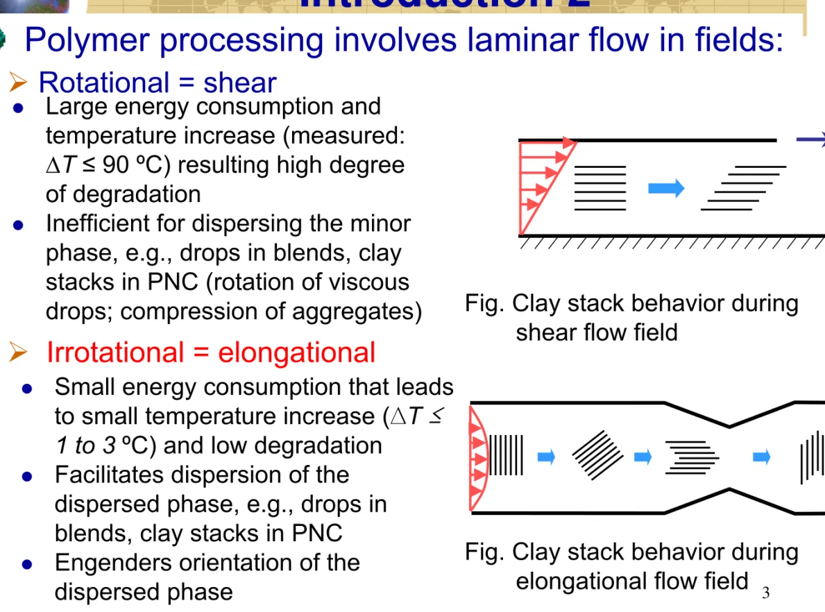
Polymer processing involves laminar flow in fields:
¾
Rotational = shear
z
Large energy consumption and
temperature increase (measured:
∆T ≤ 90 ºC) resulting high degree
of degradation
z
Inefficient for dispersing the minor
phase, e.g., drops in blends, clay
stacks in PNC (rotation of viscous
drops; compression of aggregates)
Fig. Clay stack behavior during
shear flow field
¾
Irrotational = elongational
z
Small energy consumption that leads
to small temperature increase (∆T
≤
1 to 3
ºC) and low degradation
z
Facilitates dispersion of the
dispersed phase, e.g., drops in
blends, clay stacks in PNC
z
Engenders orientation of the
dispersed phase
Fig. Clay stack behavior during
elongational flow field
Introduction
Melt flow from extruder
To die
Extensional Flow Mixer, EFM-3
(Designed for polymer blend)
Spiral pipes Spiral mandrel Upper flow channel Lower flow channel Seal bushing Flange to die Extensional flow zone Outer wall End cap Flange onto extruder
Redesigned EFM, EFM-N
Designed for dispersing
nanoparticles
Orient organoclay
Peel off organoclay
Randomize the flow
Objectives
Investigation of the effect of EFM with new C-D
geometry for dispersing the clay (EFM-N) on
compounding conditions compared with the
commercial EFM (EFM-3)
Investigation of the effects of single screw extruder
(SSE) + EFM-N on clay dispersion compared with
SSE + EFM-3 and twin screw extruder (TSE)
Investigation of the effects of SSE + EFM-N on
mechanical performances compared with SSE +
EFM-3 and TSE
Materials
PA-6 (UBE1015B, M
W= 21.7 kg/mol, Ube Industries) dried
for 48h at 80ºC, without stabilizers.
PP (Profax-PDC1274, M
W= 250 kg/mol, Basell
Polyolefins), without stabilizers.
PP-MA1 (Epolene 3015, 1.31wt% MAH, M
W= 47kg/mol,
Eastman Chemicals)
PP-MA2 (Polybond 3150, 0.5wt% MAH, M
W= 330kg/mol,
Crompton)
Cloisite 15A (C15A, MMT di-methyl di-hydrogenated
tallow ammonium, Southern Clay Products) dried for 24h
at 100ºC
Method of compounding
Single screw extruder (SSE)
EFM-3 or EFM-N
Masterbatches (MB) were prepared using co-rotation
intermeshing twin screw extruder (N = 200rpm, Q = 5kg/h)
under dry N
2:
(1)
PA-6 + 4wt% C15A (T=240ºC)
(2)
PP + 20wt% PP-MA + 10wt% C15A (T=240ºC)
PNC was prepared by diluting MB with the matrix polymer in a
TSE, SSE or SSE + EFM (EFM-3 or EFM-N). The C-D gap: h
= 15, 30, 100, 300 (±3)µm.
Characterization of PNC
X-ray diffraction (XRD)
The mean interlayer spacing, d
001(Bragg)
The number of platelets per stack, N (Scherer)
The relative amount of clay platelets absent in stacks, X
E(%)
High resolution transmission electron microscopy
(HRTEM)
Mechanical properties
Tensile properties (strength, modulus and elongation)
Flexural properties (strength and modulus)
Figure 1: The relationship between the gap and the pressure at the inlet of C-D plate. 0 5 10 15 20 25 30 35 40 45 1 10 100 1000 (60) (48) (35) (23) (25) (31) (34) (19) SSE+EFM-N SSE+EFM-3 EFM gap (µm)
Pressure and temperature vs. EFM gap on PP based PNC
Figure 2: The relationship between the gap and the polymer
temperature at the die exit.
180 185 190 195 200 205 210 1 10 100 1000 (60) (48) (35) (23) (34) (25) EFM gap (µm) SSE+EFM-3 SSE+EFM-N ( ): screw rotation speed
Pressure at the inle
t of C-D plate (MPa)
Polymer temper
ature at the die exit (
°
C)
Barrel temperature: 180℃ Throughput: 10kg/h
The compounding conditions using EFM-N were more
severe than those using EFM-N on PP based PNC
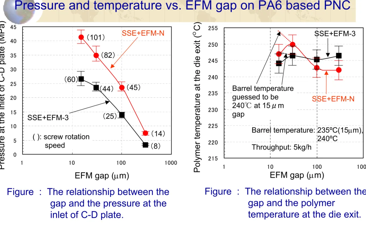
Pressure and temperature vs. EFM gap on PA6 based PNC
215 220 225 230 235 240 245 250 255 1 10 100 1000 0 5 10 15 20 25 30 35 40 45 1 10 100 1000Figure : The relationship between the gap and the pressure at the inlet of C-D plate. Barrel temperature: 235ºC(15µm), 240ºC Throughput: 5kg/h SSE+EFM-N SSE+EFM-3 EFM gap (µm)
Pressure at the inle
t of C-D plate (MPa)
Figure : The relationship between the gap and the polymer
temperature at the die exit.
EFM gap (µm)
Polymer temper
ature at the die exit (
°
C) SSE+EFM-3 SSE+EFM-N (101) (82) (60) (44) (45) (25) (14) (8) Barrel temperature guessed to be 240℃ at 15μm gap ( ): screw rotation speedThe compounding conditions using EFM-N were more
severe than those using EFM-N on PA6 based PNC
11
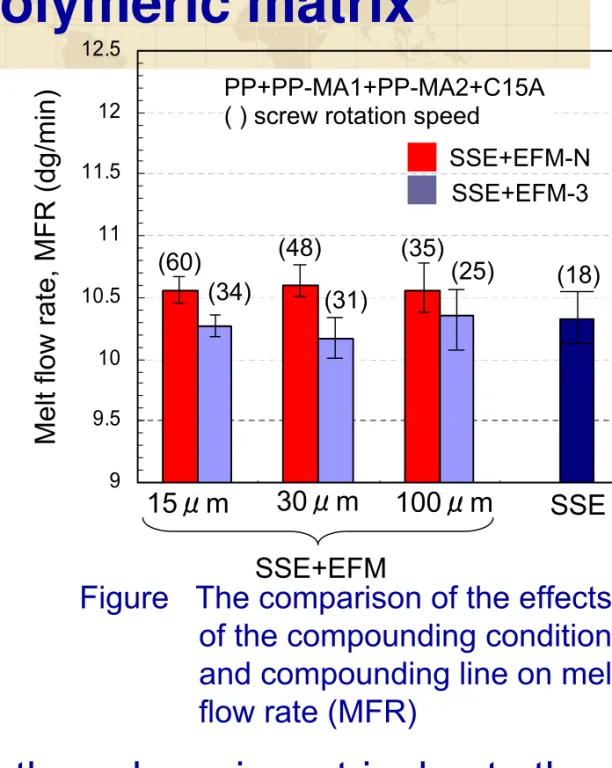
Effect on the polymeric matrix
9 9.5 10 10.5 11 11.5 12 12.5 1 2 3 4 (60) (34) (48) (31) (35) (25) (18) SSE+EFM-N SSE+EFM-3 15μm 30μm 100μm PP+PP-MA1+PP-MA2+C15A ( ) screw rotation speed
SSE SSE+EFM
Melt flow rate, MFR (dg/min)
Figure The comparison of the effects of the compounding condition and compounding line on melt flow rate (MFR)
MFR of PP extruded at 180°C through SSE + EFM-N with the EFM gap of 15µm gave the MFR = 11.94 (11.72 to 12.13) dg/min, which is the almost
same as the data of Basell data sheet (MFR=12).
Addition of organoclay and
compatibilizing mixture of PP-MA’s caused a decrease to MFR = 10.3 ± 0.2 in SSE alone or in SSE + EFM-3. The use of SSE + EFM-N increases the MFR to about 10.6 ± 0.2 dg/min even at the most severe compounding conditions (15µm)
EFM-N has benign effect on the polymeric matrix due to the
absence of shear degradation, although it made
Figure . The XRD scan for PP based PNC (SSE, SSE+EFM-3) 0 2000 4000 6000 8000 10000 12000 1 2 3 4 5 6 7 8 9 10 0 2000 4000 6000 8000 10000 12000 1 2 3 4 5 6 7 8 9 10 SSE SSE+EFM-3 (gap=15µm) SSE+EFM-3 (gap=30µm) SSE+EFM-3 (gap=100µm) SSE+EFM-3 (gap=300µm)
2
θ (degree)
2
θ (degree)
Intensity
(CPS)
Intensity
(CPS)
SSE SSE+EFM-N (gap=15µm) SSE+EFM-N (gap=30µm) SSE+EFM-N (gap=100µm) SSE+EFM-N (gap=300µm)Figure . The XRD scan for PP based PNC (SSE, SSE+EFM-N)
Barrel temperature: 180°C Throughput: 10kg/h
XRD measurement of PP based PNC
Compounding PP based PNC in SSE+EFM-N did not significantly
13
3 3.2 3.4
0.0001 0.001 0.01 0.1
Figure : Gap effect on interlayer
spacing (d
001).
Figure 3: Gap effect on incremental
exfoliation (Ext), and number
of platelets per stack (N).
0 10 20 30 0.0001 0.001 0.01 0.1 1 2 3 4 Degree of exfoliation, X E (%) Inverse gap, 1/h (µm-1)
Number of platelet per
s tack, N (-) EFM-3: N EFM-N: N EFM-3: Exf EFM-N: Exf Interlayer spacing, d 001 (% ) Inverse gap, 1/h (µm-1) EFM-3 EFM-N Barrel temperature: 180℃ Throughput: 10kg/h
Results of XRD: d001, X
E
and N v.s. gap
d
001and N were not correlate with the compounding
conditions. However, X
Esystematically increases with
Figure TEM micrographs of PP based PNC
(a) SSE (b) SSE + EFM-3
(EFM gap=15µm)
(c) SSE + EFM-N (EFM gap=15µm)
TEM observation ( × 50k)
Large and long
aggregates with 10
to 20 clay platelets
in stack
Few short stacks
Large but shorter and
looser aggregates
Stacks with 3 to 4
layers
Higher particle density
Large and tight but
shorter aggregates
Few short stacks
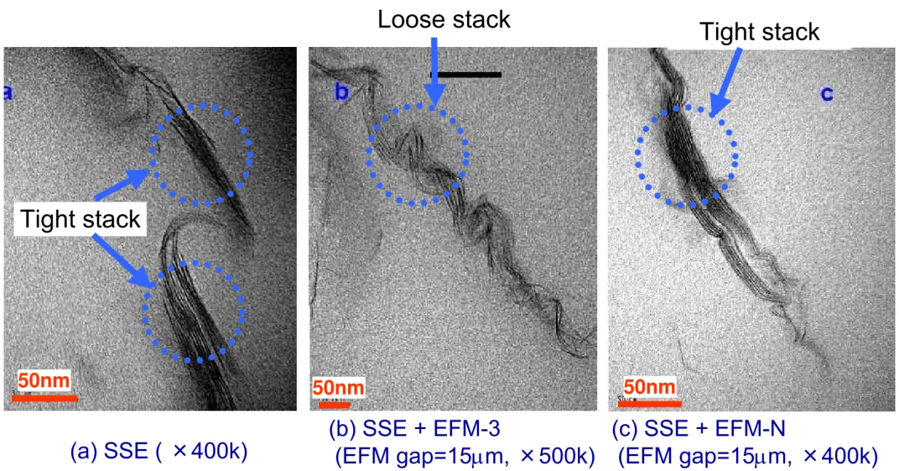
TEM observation (× 400k, × 500k)
Figure TEM micrographs of PP based PNC on high magnification
(a) SSE ( ×400k) (b) SSE + EFM-3 (EFM gap=15µm, ×500k) 50nm 50nm 50nm (c) SSE + EFM-N (EFM gap=15µm, ×400k)
Tight stack
Loose stack
Tight stack
0 2000 4000 6000 8000 10000 12000 14000 1 2 3 4 5 6 7 8 9 10 0 2000 4000 6000 8000 10000 12000 14000 1 2 3 4 5 6 7 8 9 10 SSE SSE+EFM-N (gap=15µm) SSE+EFM-N (gap=30µm) SSE+EFM-N (gap=100µm) SSE+EFM-N (gap=300µm) SSE SSE+EFM-3 (gap=15µm) SSE+EFM-3 (gap=30µm) SSE+EFM-3 (gap=100µm) SSE+EFM-3 (gap=300µm) 2θ (degree) 2θ (degree) Intensity (CPS) Intensity (CPS)
XRD measurement of PA6 based PNC
Figure . The XRD scan for PA6 based PNC (SSE, SSE+EFM-3)
Figure . The XRD scan for PA6 based PNC (SSE, SSE+EFM-N)
Barrel temperature: 235°C, 240°C Throughput: 10kg/h
Compounding PA6 based PNC in SSE+EFM significantly modified the clay
dispersion. At the small EFM gap (15µm, 30µm), the diffraction peaks did
17
XRD measurement of PA6 based PNC
Figure The XRD scan for PA6 based PNC using various kind of
compounding methods
2θ (degree)
Intensity
(CPS)
Dilution of PA6 MB to 2% C15A in SSE+EFM-N (gap=30µm) resulted in
full exfoliation – the diffractgram is similar to that of the commercial PA6
based PNC, UBE1015C2 (PA6 grafted on to MMT)
18 d001(UBE1015C2)=5.33nm TSE(d001=4.44nm) UBE1015C2(XE=80.8) N(UBE1015C2 )=2.44 TSE(N=2.79) TSE (XE =50.7)
Figure . Gap effect on interlayer spacing (d001)
Figure . Gap effect on incremental
exfoliation (XE), and number of platelets per stack (N)
Compounding PA6 based PNC in SSE+ EFM-N with progressively reduced EFM gap resulted in expansion of d001, while in SSE+EFM-3, d001 was about constant
The degree of clay dispersion using SSE+EFM-N is better than that using TSE Comparable tests of the commercial UBE1015C2 (PA6 grafted onto MMT)
19
50nm 50nm 50nm
TEM observations (× 300k)
(a) SSE
(b) SSE + EFM-3
(C-D gap=30µm)
(c) SSE + EFM-N
(C-D gap=30µm)
Several largeaggregates with 10 to 12 clay platelets in stack Short stacks with 3 to 4 platelets may be seen
No large aggregate
Stacks with 2 to 3 layers Many single layer stacks Oriented stacks
Higher particle density Many single layer stacks Twisted clay platelets Absence of triplets
TEM observations (× 200k, × 300k)
50nm 50nm
(a) TSE
(b) SSE + EFM-N (C-D gap=30µm)
Figure TEM micrographs of PA6 based PNC
Clay dispersion using SSE+EFM-N with 30µm EFM gap is
better than that using TSE
21
Tensile test results (PP based PNC)
30 31 32 33 34 35 36 37 0 20 40 60 80 100
Figure 4 : The relationship between
EFM gap and tensile modulus.
Figure : The relationship between EFM
gap and tensile strength.
1600 1700 1800 1900 2000 2100 2200 0 20 40 60 80 100 EFM gap (µm)
Tensile modulus (MPa)
SSE+EFM-3 (PP+PP-MA1+PP-MA2+C15A) SSE+EFM-N (PP+PP-MA1+PP-MA2+C15A) (60) (48) (35) (25) (34) (31) (48) SSE+EFM-N (PP) TSE (PP+PP-MA1+PP-MA2+C15A)
Tensile strength (MPa)
EFM gap (µm) SSE+EFM-N (PP+PP-MA1+PP-MA2+C15A) SSE+EFM-3 (PP+PP-MA1+PP-MA2+C15A) (35) (25) (48) (31) (60) (34) (48) SSE+EFM-N (PP) TSE (PP+PP-MA1+PP-MA2+C15A)
The modulus and the strength of PP based PNC were higher than those of pure PP – 21.8 to 25.9% higher (the modulus), 13.1 to 14.3% higher (the strength) For most EFM gaps the modulus and the strength obtained using SSE+EFM-N were higher than those obtained using SSE+EFM-3
Flexural test results (PP Based PNC)
1500 1600 1700 1800 1900 2000 2100 2200 0 20 40 60 80 100 48 50 52 54 56 58 60 62 0 20 40 60 80 100Figure :The relationship between EFM
gap and flexural modulus.
Figure :The relationship between EFM
gap and flexural strength.
EFM gap (µm)
Flexural modulus (MPa)
SSE+EFM-3 (PP+PP-MA1+PP-MA2+C15A) SSE+EFM-N (PP+PP-MA1+PP-MA2+C15A) (60) (48) (35) (25) (34) (31) (48) SSE+EFM-N (PP) TSE (PP+PP-MA1+PP-MA2+C15A)
Flexural strength (MPa)
EFM gap (µm) SSE+EFM-N (PP+PP-MA1+PP-MA2+C15A) SSE+EFM-3 (PP+PP-MA1+PP-MA2+C15A) (35) (25) (48) (31) (60) (34) (48) SSE+EFM-N (PP) TSE (PP+PP-MA1+PP-MA2+C15A)
The modulus and the strength of PP based PNC were higher than those of pure PP – 32.9 to 34.2% higher (the modulus), 17.1 to 19.9 % higher (the strength) For most EFM gaps the modulus and the strength obtained using SSE+EFM-N were higher than those obtained using SSE+EFM-3
18 20 22 24 26 28 30 32 34 36 38 0 20 40 60 80 100
Figure :The relationship between EFM
gap and impact strength.
EFM gap (µm) Impact strength (J/m) SSE+EFM-3 (PP+PP-MA1+PP-MA2+C15A) (60) (48) (35) (25) (34) (31) (48) SSE+EFM-N (PP) TSE (PP+PP-MA1+PP-MA2+C15A) SSE+EFM-N (PP+PP-MA1+PP-MA2+C15A)
Impact result (PP based PNC)
The impact strength of PP based PNC were higher than those of pure PP – 18.3 to 26.2% higher
The impact strength obtained using SSE+EFM was higher than that obtained using TSE
Conclusions
EFM-N had benign effect on the polymer matrix due to the
absence of shear degradation, although it made
compounding conditions more severe.
Clay dispersion obtained by using SSE + EFM-N were
better than that obtained by using SSE + EFM-3 and TSE.
The best dispersions were obtained for small EFM gaps at
15 or 30µm with compounding PA6/C15A in SSE + EFM-N
resulted in full exfoliation.
TEM micrographs show a better dispersion in PNC from
SSE + EFM-N than from SSE + EFM-3, or TSE.
Clay dispersion of compounded PA6/C15A in SSE + EFM-N
was comparable to that of commercial UBE1015C2.
Most of the mechanical performance compounded using
SSE + EFM-N were higher or comparable to those
compounded using SSE + EFM-3, or TSE due to superior
clay dispersion of SSE + EFM-N.
Acknowledgments
Florence Perrin
Manon Plourde
(form National Research Council Canada,
Industrial Materials Institute)
Experimental conditions (PA-6 based PNC)
Material Composition (wt%) Test No. PA-6 C15A 5.5±0.1 1163 PA-1 SSE+EFM-3 60 6.0±0.3 PA-2 SSE+EFM-N 101 5.1±0.5 PA-4 SSE+EFM-N 82 4.6±0.3 PA-5 SSE+EFM-3 25 5.3±0.4 1071 PA-7 SSE+EFM-3 8 4.8±0.1 PA-8 SSE+EFM-N 300 14 5.2±0.2 1147 100 1108 15 235 1138 5.1±0.4 5.1±0.6 6 44 45 2 EFM gap h(μm) PA-0 SSE - 240 PA-3 SSE+EFM-3 30 PA-6 SSE+EFM-N 240 98Compounding equipments SSE and EFM temperature (
℃ ) Screw speed (rpm) Measured throughput (kg/h) Residence time (s)
Experimental conditions (PP based PNC)
Material Composition(wt%) Test No. PP PP-MA1 PP-MA2 2 2 C15A 10.1 1163 PP-1 SSE+ EFM-3 34 10.1±0.1 PP-2 EFM-NSSE+ 60 9.9±0.1 PP-4 SSE+ EFM-N 48 10.1±0.2 PP-5 SSE+ EFM-3 25 9.9±0.2 1071 PP-7 SSE+ EFM-3 19 9.9 PP-8 SSE+ EFM-N 23 10.1±0.1 1147 300 100 1108 15 1138 10.0±0.2 10.1 18 31 35 2 EFM gap h(μm) PP-0 SSE -PP-3 EFM-3SSE+ 30 PP-6 SSE+ EFM-N 180 94Compounding equipments SSE and EFM
temperature ( ℃ ) Screw speed (rpm) Measur ed throughput (kg/h) Residence time (s)
80 82 84 86 88 90 92 94 96 98 100 0 10 20 30 40 50 60 70 80 90 100 110 2800 2900 3000 3100 3200 3300 3400 3500 3600 3700 3800 3900 0 10 20 30 40 50 60 70 80 90 100 110
Figure : The relationship between EFM
gap and tensile modulus.
Figure: The relationship between EFM
gap and tensile strength.
EFM gap (µm)
Tensile modulus (MPa)
SSE+EFM-3 (PA6+C15A) (101) (82) (45) (25) (60) (44) (101) SSE+EFM-N (PA6) TSE (PA6+C15A)
Tensile strength (MPa)
EFM gap (µm) SSE+EFM-N (PA6+C15A) SSE+EFM-3 (PA6+C15A) (101) (82) (45) (25) (60) (44) (101) SSE+EFM-N (PA6) TSE (PA6+C15A) SSE+EFM-N (PA6+C15A)
Tensile results (PA6 based PNC)
The modulus and the strength of PA6 based PNC were higher than those of pure PA6 – 19.0 to 24.1% higher (the modulus), 8.4 to 11.4% higher (the strength)
For most EFM gaps the modulus obtained using SSE+EFM-N were higher than those obtained using SSE+EFM-3
Flexural results (PA6 based PNC)
134 136 138 140 142 144 146 148 150 152 154 156 158 160 162 164 166 0 10 20 30 40 50 60 70 80 90 100 110 2800 2900 3000 3100 3200 3300 3400 3500 3600 3700 3800 3900 4000 0 10 20 30 40 50 60 70 80 90 10 0 11 0Figure : The relationship between EFM
gap and flexural modulus.
Figure: The relationship between EFM
gap and flexural strength.
EFM gap (µm)
Flexural modulus (MPa)
SSE+EFM-3 (PA6+C15A) (101) (82) (45) (25) (60) (44) (101) SSE+EFM-N (PA6) TSE (PA6+C15A)
Flexural strength (MPa)
EFM gap (µm) SSE+EFM-N (PA6+C15A) SSE+EFM-3 (PA6+C15A) (101) (82) (45) (25) (60) (44) (101) SSE+EFM-N (PA6) TSE (PA6+C15A) SSE+EFM-N (PA6+C15A)
The modulus and the strength of PA6 based PNC were higher than those of pure PA6 – 16.2 to 20.4% higher (the modulus), 10.1 to 11.7% higher (the strength) The modulus obtained using SSE+EFM were higher than that obtained using TSE
Impact results (PA6 based PNC)
20 22 24 26 28 30 32 34 36 38 40 0 10 20 30 40 50 60 70 80 90 100 110Figure: The relationship between EFM
gap and impact strength.
Impact strength (J/m) EFM gap (µm) SSE+EFM-3 (PA6+C15A) (101) (82) (45) (25) (60) (44) (101) SSE+EFM-N (PA6) TSE (PA6+C15A) SSE+EFM-N (PA6+C15A)
The impact strength of PA based PNC obtained using
SSE+EFM-N at 15µm gap was comparable to that of pure PA6 The impact strength obtained using SSE+EFM was higher than