HAL Id: hal-01526247
https://hal.laas.fr/hal-01526247
Submitted on 22 May 2017
HAL is a multi-disciplinary open access
archive for the deposit and dissemination of
sci-entific research documents, whether they are
pub-lished or not. The documents may come from
teaching and research institutions in France or
abroad, or from public or private research centers.
L’archive ouverte pluridisciplinaire HAL, est
destinée au dépôt et à la diffusion de documents
scientifiques de niveau recherche, publiés ou non,
émanant des établissements d’enseignement et de
recherche français ou étrangers, des laboratoires
publics ou privés.
To cite this version:
Jérémy Dulout, Corinne Alonso, Lionel Séguier, Bruno Jammes. Development of a photovoltaic low
voltage DC microgrid for buildings with energy storage systems. ELECTRIMACS 2017, Jul 2017,
Toulouse, France. 6p. �hal-01526247�
1
D
EVELOPMENT OF A PHOTOVOLTAIC LOW VOLTAGE
DC
MICROGRID FOR BUILDINGS WITH
E
NERGY STORAGE SYSTEMS
Jérémy Dulout, Corinne Alonso, Lionel Séguier, Bruno Jammes
LAAS-CNRS, Université de Toulouse, CNRS, UPS, France e-mail: {jdulout, alonsoc, lseguier, jammes}@laas.fr
Abstract – In order to develop a sustainable datacenter, which would help to validate energy management and task scheduling algorithms, a low voltage direct current (LVDC) microgrid (MG) has been deployed in the ADREAM Building-Integrated Photovoltaic (BIPV) of the LAAS-CNRS in Toulouse, France. This MG is composed of a 1 kWp PV source, 300 Ah – 36 V lead-acid batteries, 330 F – 48 V supercapacitor (SC) pack and DC loads (cloud servers, USB chargers, sensors monitoring an apartment…). A very simple and efficient energy flow management strategy, based on the “DC bus signaling” approach has been implemented. It takes advantage of the DC bus architecture and enables a scalable electrical structure constituted of several sources, loads and storage elements easy to connect/disconnect via their converters. The development of this MG put in evidence the need for future theoretical developments regarding the determination of optimal DC bus signaling thresholds.
Keywords – LVDC Microgrid (MG), Photovoltaic (PV) source, DC Voltage Bus
Control, Energy storage systems (ESS)
1. I
NTRODUCTIONThe famous “current war” between the direct current (DC) (Thomas Edison) and the alternating current (AC) (Nikola Tesla and George Westinghouse) is the root of our actual centralized electric power distribution and transmission system since the end of the 19th century.
During more than a century, transformers have been the only way to easily step-up (or down) voltage levels to provide safe and efficient transportation and use of electricity but the development of efficient and reliable power converters during the last decades is a game changer [1]-[4].
To tackle the issue of growing energy demand and fossil resources depletion, several incentive programs have helped to develop different renewable energy sources to create a new energy mix more sustainable. However, these new sources of energy are not adapted to our actual centralized AC distribution grid. In order to integrate a high level of renewable sources in our electric production process, as asked in the European directives H2030 [5], a new distributed architecture has arisen 2 decades ago under the name of microgrid (MG). This architecture is often coupled with smart metering and proper management to control renewable sources, energy storages systems and loads. Moreover, as more and more sources and loads are DC native (photovoltaic (PV) sources, batteries, computers, LED lighting,…), the study of DC MG in terms of efficiency, control and robustness seems promising.
In this context, the LAAS-CNRS has decided to create a LVDC MG in the ADREAM Building - Integrated Photovoltaic (BIPV). This DC bus has been deployed in the context of the internal project “OpenData Platform for ADREAM” (OPA). OPA is a multi-disciplinary platform which addresses the integration of internet of things (IoT), optimal management of datacenter servers, smart control of LED lightings and energy management issues. The LVDC MG will allow us to study the practical feasibility, the stability and the efficiency of DC MGs compared to the classical power distribution.
This paper is organized as follows: in section 2, the ADREAM building is presented. Then, the development of OPA MG is explained. The energy management of the MG with different ESSs is detailed in section 4 and the experimental platform is presented in section 5.
2. ADREAM
BIPV
The ADREAM BIPV [6] has been inaugurated in 2012. One of the challenges of this experimental building monitored by more than 7000 sensors is to develop and evaluate new control and communication strategies with smart appliances in real conditions. Another objective of ADREAM is to become a net zero emission building (NZEB).
2 and the 100 kWp of PV installed power is connected
to 400 V AC utility grid. The 25 kWp of PV panels covering a part of the second floor of this building (Fig. 1) are dedicated to research works: PV panels modelling, development of MPPT algorithms, impact of shadows on PV production, forecasting with meteorological data, overall efficiency of PV systems… A meteorological station has been added to this experimental platform to measure speed and direction of wind, global and diffuse irradiance, temperature and humidity. Three reversible heat pumps are also used for cold/hot water and air cooling/heating. Nevertheless, the generation from renewable energy sources (RES) and the actual energy storage system are not sufficient to fulfill all the energy demand and achieve the net-ZEB challenge.
Fig. 1: PV array on the second floor of the experimental ADREAM BIPV in LAAS-CNRS. Data from most of the sensors of this building are recorded every minute since 2012. In order to reduce the energy consumption, lighting and ambient temperature are supervised and regulated through the analysis of data given by different sensors (luminance, motion detector…).
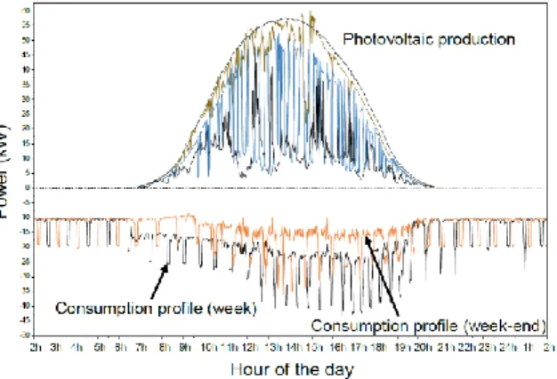
Fig. 2. ADREAM daily PV production and consumption profiles (may 2015).
of the ADREAM building are depicted in Fig. 2. It is shown that the PV profile may be very intermittent and can be very different from a day to another (the presented data correspond to the same week of may in 2015). It can be noticed that the building is consuming a lot of electricity even during week-ends when there is nearly no user in the building. The large peaks of consumption are due to the start of compressor motors of heat pumps.
As illustrated in Fig. 3, research in robotics is also performed in a living space from the ADREAM building.
Fig. 3. Some sensors and experimental benches of the ADREAM building.
59 kWh of lead-acid batteries and 56kWh of lithium batteries have been recently installed in the building. These ESSs, connected to the AC grid, will be used to deploy and validate energy management algorithms in order to reach the NZEB goal, minimize the impact of the PV production on the grid and the cost of electricity.
Different studies reported the potential benefits of DC MGs in terms of efficiency by eliminating AC/DC conversion stages [7]-[9]. Moreover, due to the increasing number of DC native electrical sources and loads, a LVDC platform inside the actual ADREAM BIPV has been supported by the LAAS-CNRS. This new DC MG is described in the next section.
3. Design and development of OPA MG
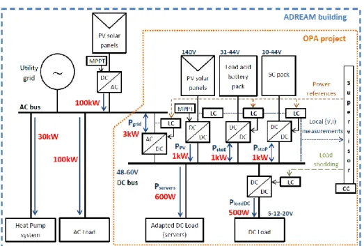
The overall architecture of OPA and ADREAM building is described in Fig. 4. As a first step, a PV string of 1 kWp is feeding a 48-60 V DC bus connected to 300 Ah – 36 V lead-acid batteries, 330 F – 48 V supercapacitors (SCs) and DC loads (servers, USB chargers, sensors…).The OPA MG can operate either in “islanded mode” (isolated from the main grid) or in “connected mode” (this connection to the utility grid may be used in case of exceptional bad weather conditions with totally discharged ESSs or during sunny days with fully charged ESSs).
3 Fig. 4. Architecture of the new OPA LVDC MG in the ADREAM BIPV
Each storage unit is connected to the MG through a DC/DC converter driven by a local controller (LC). The LC also sends local measurements of voltage and current to the central Controller (CC) that is responsible for the energy management of the MG. It defines the operating mode of the MG and sends references to the LCs. Nevertheless, efforts have been made to decentralize the management of the MG in case of communication failure. More explanations are given in the section 4.
These DC/DC converters (current bidirectional) and their control boards have been designed in LAAS-CNRS (Fig. 5). It enables to implement specific control and communication between LCs and CC (I2C bus).
Fig. 5. Power electronics developed in the LAAS On the left - 1kW bidirectional DC/DC converter,
On the right – Power converter control board.
4. C
ONTROL OF THEMG
Different methods of energy management in a MG are described in [10]-[11].
In a previous paper [12], we proposed a method of current sharing between a buck and a boost converter connected to the same DC bus to improve the
lifetime of a battery. In [13], a sizing methodology of a lithium battery pack based on the ADREAM building power balance is developed.
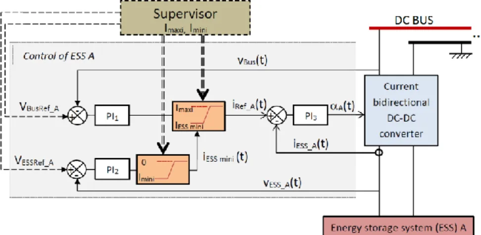
The state diagram of the ESSs management and the cascade regulation that are implemented in all ESS LCs are presented in Fig. 6 and 7, respectively. A control derived from “DC bus signaling” [14]-[16] has been developed in order to manage the energy flows between the different sources. The MG management has been designed to limit the number of charge/discharge cycles of the battery pack per day. To do this, the output voltage reference of the power converter associated to the SCs is set lower than the reference of the battery pack converter (53V and 54V respectively). Moreover, the batteries cannot be discharged as long as the SCs are not empty and can only be charged after the SCs are full. The experimental results are given in Fig. 8. In this figure, the sign of the currents going to the bus has been set positive.
4 Fig. 7. Control scheme of a DC-DC converter connected to an ESS.
The different states of the energy management presented in Fig. 6 can be explained as follows: State 1: In this initial state, the battery is not allowed to charge or discharge (Imaxi=Imini=0 in Fig. 7). Based
on the power balance of the MG, the pack of SCs may be charging (PLoad<PPV) or discharging
(PLoad>PPV) to regulate the voltage of the DC bus at
52 V.
When the SCs are fully charged (44 V), it is no longer possible to store energy in this ESS so the voltage of the DC bus is increasing if the power balance remains positive. Once the voltage of the DC bus is higher than 53.5 V, the supervisor allows to charge the batteries (Imaxi =18 A) and the MG mode
changes to state 2. The voltage of the bus is regulated at 53 V (cf. Fig. 8-B, t=9717)
Conversely, when the SCs are empty and the power balance is negative, the voltage of the bus decreases.
Once it goes below 51.5 V, the supervisor allows batteries to be only discharged (Imini =-18 A and
Imaxi =0 A) and prohibits SCs for charging (cf. Fig.
8-C, t= 12 224). In this case the MG mode goes to state 3. The same state can be obtained from state 2, when the SCs are no longer able to meet the load demand.
State 2: It is the “normal mode” during the day. Batteries are only allowed to charge and SCs can either charge or discharge. The advantage of this mode can be clearly observed in Fig. 8-D. Indeed, the SCs are regulating the DC bus voltage during partly cloudy days, avoiding micro-cycles from the batteries.
State 3: All ESSs are allowed to only be discharged. If the PV production is higher than the load demand, the voltage of the DC bus increases. When it reaches 53 V, the supervisor allows the SCs to be charged and the MG goes to state 1 (cf. Fig 8-E, t=4739).
5 The state diagram only describes the energy
management between the DC bus and the storage elements. To represent the entire energy management procedure, the cases where all storage elements are fully charged or discharged must be considered. The entire energy management strategy of the LVDC OPA MG can be represented by the Fig. 9.
Fig. 9. Principle of LVDC OPA MG energy management
During steady states operations (dotted lines in the Fig. 9), only one power converter controls the voltage level of the DC bus, the other ones operate as current sources. The voltage source that corresponds to A, B, C and D values of the bus voltage are respectively: the DC/AC, the lead-acid batteries, the SCs and the AC/DC converter.
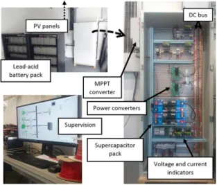
Fig. 10. Experimental OPA DC MG
5. M
ONİTORİNG AND SUPERVİSİONThe DC bus of the OPA project is presented in Fig. 10. In this MG, a commercialized MPPT converter is used to connect the PV panels. It works independently from the other power converters. A
commercialized inverter enables energy exchanges with the main grid, in case of overproduction from renewable sources.
LabWindows/CVI has been used to develop a monitoring and supervision application of the DC bus as presented in Fig. 11. The voltage of the DC bus as well as the currents delivered by the solar pannels, lead-acid batteries, SCs, utility grid and absorbed by the servers and smart appliances are sensed and saved in a database. The state of charge (SOC) of each ESS is also measured.
Fig. 11. Graphical user interface of the OPA MG
6. C
ONCLUSIONA new LVDC microgrid (MG), including monitoring and supervision has been developed in LAAS-CNRS in order to validate task planning algorithms for sustainable data centers supplied by renewable sources. In addition, this MG will allow to validate previous works on sizing and scheduling of ESSs in real conditions.
The energy management algorithm proposed in this paper is a very simple implementation of “DC bus signaling”. This approach take advantage of the architecture of DC bus (each source or load is connected through a DC/DC or AC/DC converter) to allow its voltage to vary significantly. Our algorithm can be implemented in each converter’s local controller or in the central controller (supervisor). The first solution doesn’t need any communication between the converters and the second one allows to adapt the management strategy in real time (for example in order to minimize the cost of energy delivered to the load).
The MG presented in this paper associates batteries and SCs in order to avoid micro-cycles from the battery during partly cloudy days. However, a cost-effectiveness analysis of this configuration must be done. The voltage reference values have been empirically chosen, based on the several experimental tests. It should be important to develop a methodology to determine the best values of these references according to the dynamic of the DC bus (and connected power converters) and according to
6 requirements.
R
EFERENCES[1] F. Blaabjerg, R. Teodorescu, M. Liserre, A. V. Timbus, “Overview of Control and Grid Synchronization for Distributed Power Generation Systems,” IEEE Transactions on Industrial
Electronics, vol. 53, no. 5, pp. 1398-1409, Oct. 2006
[2] Peng Wang, Lalit Goel, Xiong Liu, Fook Hoong Choo, “Harmonizing AC and DC: A Hybrid AC/DC Future Grid Solution,” IEEE Power and Energy Magazine, vol. 11 issue 3, pp 76-83, May/June 2013. [3] S. Parhizi, H. Lotfi, A. Khodaei, S. Bahramirad, "State of the Art in Research on Microgrids: A Review," IEEE Access, vol. 3, pp. 890-925, 2015. [4] G. AlLee, W. Tschudi, "Edison Redux: 380 Vdc Brings Reliability and Efficiency to Sustainable Data Centers," IEEE Power and Energy Magazine, vol. 10, no. 6, pp. 50-59, Nov.-Dec. 2012 [5] http://ec.europa.eu/energy/en/topics/energy-strategy/2030-energy-strategy [Accessed: 18.05.2017] [6] https://www.laas.fr/public/en/adream [Accessed: 18.05.2017]
[7] Yunjie Gu, Xin Xiang, Wuhua Li, Xiangning He, “Mode-Adaptive Decentralized Control for Renewable DC Microgrid With Enhanced Reliability and Flexibility,” IEEE Transactions on Power Electronics, vol. 29, no. 9, pp. 5072 – 5080, Sept. 2014.
[8] J. M. Guerrero, J. Matas, L. Garcia de Vicuna, M. Castilla, J. Miret, "Decentralized Control for Parallel Operation of Distributed Generation Inverters Using Resistive Output Impedance," IEEE Transactions on
Industrial Electronics, vol. 54, no. 2, pp. 994-1004,
April 2007.
[9] Y. M. Atwa, E. F. El-Saadany, M. M. A. Salama, R. Seethapathy, "Optimal Renewable Resources Mix
IEEE Transactions on Power Systems, vol. 25, no. 1,
pp. 360-370, Feb. 2010.
[10] Scott Backhaus et al., “DC Microgrids Scoping Study - Estimate of Technical and Economic Benefits,” report from Los Alamos National Laboratory, LA‐UR‐15‐22097, march 2015. [11] N. Eghtedarpour, E. Farjah, "Distributed charge/discharge control of energy storages in a renewable-energy-based DC micro-grid," IET
Renewable Power Generation, vol. 8, no. 1, pp.
45-57, January 2014.
[12] Jérémy Dulout, Bruno Jammes, Lionel Séguier, Corinne Alonso, “Control and design of a hybrid energy storage system,” European Conference on Power Electronics and Applications (EPE'15 ECCE-Europe), 2015.
[13] Jérémy Dulout, Amjad Anvari-Moghaddam, Adriana Luna, Bruno Jammes, Corinne Alonso, Josep M. Guerrero, “Optimal sizing of a lithium battery energy storage system for grid-connected photovoltaic systems,” International Conference on DC Microgrids (ICDCM), June 2017.
[14] Tomislav Dragičević, Josep M. Guerrero, Juan C. Vasquez, Davor Škrlec, “Supervisory Control of an Adaptive-Droop Regulated DC Microgrid With Battery Management Capability,” IEEE Transactions on Power Electronics, vol. 29, no. 2, pp. 695 – 706, Feb. 2014.
[15] J. Schönberger, R. Duke, S. D. Round, "DC-Bus Signaling: A Distributed Control Strategy for a Hybrid Renewable Nanogrid," IEEE Transactions
on Industrial Electronics, vol. 53, no. 5, pp.
1453-1460, Oct. 2006.
[16] K. Sun, L. Zhang, Y. Xing, J. M. Guerrero, "A Distributed Control Strategy Based on DC Bus Signaling for Modular Photovoltaic Generation Systems With Battery Energy Storage," IEEE
Transactions on Power Electronics, vol. 26, no. 10,