• Aucun résultat trouvé

Right Harmonic Spectrum for the back-electromotive force of a n-phase synchronous motor

N/A
N/A
Protected

Academic year: 2021

Partager "Right Harmonic Spectrum for the back-electromotive force of a n-phase synchronous motor"

Copied!
9
0
0

Texte intégral

(1)

Science Arts & Métiers (SAM)

is an open access repository that collects the work of Arts et Métiers Institute of

Technology researchers and makes it freely available over the web where possible.

This is an author-deposited version published in: https://sam.ensam.eu

Handle ID: .http://hdl.handle.net/10985/9274

To cite this version :

Eric SEMAIL, Xavier KESTELYN, Alain BOUSCAYROL - Right Harmonic Spectrum for the back-electromotive force of a n-phase synchronous motor - In: IEEE Industrial Application Society Annual Meeting, Etats-Unis, 2004-10 - IAS congress - 2004

Any correspondence concerning this service should be sent to the repository Administrator : archiveouverte@ensam.eu

(2)

Right Harmonic Spectrum for the Back-Electromotive

Force of a n-phase Synchronous Motor

Eric Semail, Member IEEE, Xavier Kestelyn, Alain Bouscayrol, Member IEEE

L2EP, Laboratoire d'Electrotechnique et d' Electronique de Puissance de Lille

ENSAM, USTL LILLE, FRANCE eric.semail@lille.ensam.fr

Abstract—This paper deals with a vector control of n-phase permanent magnet synchronous machine. To use control algorithms already developed for sine-wave 3-phase machines, the spectrum of back electromotive force (EMF) must contain only odd 2k+1 harmonics which verify the following inequality,

n k+ < ≤2 1

1 . In an experimental vector control of a 5-phase

drive, two usual algorithms of sine-wave 3-phase machine are thus used to supply a machine with trapezoidal waveform back EMF. In this case, the first and third harmonics are used to

produce torque: the other harmonics, and particularly the 7th

one, induce effects as torque ripples and parasitic currents. Keywords- multi-phase; synchronous motor; multi-machine.

I. INTRODUCTION

Multi-phase machines have several advantages over conventional 3-phase ones [1]-[2] such as higher reliability and reduction of the torque pulsation magnitude. Nevertheless, their vector controls are not known as well as those of 3-phase BLDC machines [3]. For these last ones, two kinds of controls are usually distinguished on the basis of back EMF waveforms. If the back EMFs have a sinusoidal waveform then current controls in synchronous frame achieve high efficient brushless DC machines. If the back EMFs have trapezoidal waveforms, the control in stationary frame is simpler but also less efficient

[3]. For n-phase machines, particular controls have already been proposed [4]-[6] but there is no synthetic approach. This simple classification is no more obvious for n-phase machines. In fact, a more accurate harmonic analysis of back EMF is necessary to distinguish between two kinds of machines which make possible two kinds of performances. We consider only the case of machines whose number of phases is a odd number. If the harmonic spectrum of a n-phase machine contains only odd harmonics strictly inferior to n, then it is possible to achieve equivalent controls as those of sine-wave 3-phase machines. In this paper, the particular case of a 5-phase experimental (Fig1. Fig.2 Fig.3) drive is used to highlight the influence of harmonics on the vector control.

II. MULTI-MACHINE CHARACTERIZATION OF A n-PHASE MACHINE

Under assumptions of no saturation, no reluctance effect and regular spatial distribution of windings, the vectorial approach developed in [7]-[9] leads to define the equivalence of a n-phase wye-connected machine to a set of (n-1)/2 fictitious independent 2-phase machines.

A. Assumptions, notations, nomenclature 1) Nomenclature

All quantities relating to the phase n° k are written xk. • jsk: current in the phase n° k;

• usk: voltage across the phase n° k;

• φsk: flux through the phase n° k exclusively produced by the stator currents;

• φsrk: flux through the phase n° k exclusively due to the rotor magnets;

• ek: electromotive force (EMF) induced in the phase n° k only due to the rotor magnets;

• θ: mechanical angle.

2) Assumptions

Usual assumptions are used to model the machine:

• all phases are identical and regularly shifted by an angle (Fig.4):

n 2π

α = (1)

V

bus

Figure 1. Symbolic representation of the 5-leg PWM-VSI and wye-coupled 5-phase machine.

8cm

(3)

• effects of saturation and damper windings are neglected.

B. Usual modeling in a natural base

In the usual matricial approach of n-phase machines, a vector n-space is implicitly considered since vectors with n components are defined. This space is provided with an orthonormal base       = σ σ σ σ x x xn

B 1, 2,..., that can be called “natural” since the coordinates of a vector in this base are the measurable values relative to each phase.

In this paper, we consider that this space is an Euclidean vectorial space with the usual canonical dot product.

In this natural base, different vectors are defined:

σ σ σ n sn 2 2 s 1 1 s s u x u x ... u x u = + + + (2) σ σ σ n sn 2 1 1 s s j x j x ... j x j = + s2 + + (3) σ σ σ φ φ φ φs = s1x1 + s2x2 +...+ snxn (4) σ σ σ n nx e x e x e e = 1 1 + 2 2 +...+ (5) Taking into account Rs, the stator resistance per phase, the

vectorial voltage equation is:

e B / dt d j R u s s s s  +      + = σ φG (6)

The Βσ index reminds that differentiation is operated according to the Βσ natural base.

This equation can be projected onto each vector of the natural base to find again the more usual equation:

k sk k s s k s sk dt e d j R x . u u = σ = + φ + (7)

The assumptions previously defined allow to write a linear relation between the stator current vector and the stator flux vector:

( )

s s s

Λ

j

φ =

(8)

usually written with the circular matrix notation:

[ ]

[

]

              = Λ = − 1 1 3 1 2 1 1 1 n 1 1 2 1 1 1 s s s s s s s s ss1 s s s s s s s s M ... M M ... ... ... ... M ... M M M ... M M , L n n B Mat s s σ σ (9)

The modeling of the machine in the natural base is not simple because of the complexity of the matrix

[ ]

σ

s

L . It would be interesting to find a simpler form for matrix of Λs.

C. Vectorial decomposition in eigenspaces of ΛS

The equation (8) is true whatever is the chosen base associated with the stator coils. The symmetry and circularity of the inductance matrix

[ ]

σ

s

L allows to state that: • Λs belongs F eigenvalues Lg with F=(n+1)/2 and

(

)

      − =

= = 1 e g n 2 cos M L n e 1 e e s 1 s g π (10)

• the F associated eigenspaces Gg are orthogonal each other;

• the G0 eigenspace, associated with the eigenvalue L0, is a vectorial line;

• the others (n-1)/2 eigenspaces G2g (1≤g

(

n−1

)

2), associated with the others (n-1)/2 eigenvalues Lg are vectorial planes. A base of G2g plane is:

( )

( )

             =       =

= = + = = n h h h d g n h h h d g x h g n n x x h g n n x 1 1 1 1 2 sin 2 1 2 cos 2 σ σ π π (11)

Figure 3. Experimental drive.

1 s j 1 s u us2 js2 N α α ) 1 (kk s u sk j S

(4)

The orthogonality of the G2g planes allows to decompose every vector y into a sum of vectors yg obtained by orthogonal projection of y onto G2g:

− = = = 1 0 F g g g y y (12)

This kind of decomposition has already been achieved in particular cases [10] for induction machines.

Finally, as Lg are eigenvalues of Λs, a simpler expression between flux and currents can be expressed:

g F g g g F g g g s

L j − = = − = = = = 1 0 1 0 φ φ (13) D. Multi-machine concept

It is now possible to show that the torque of a multi-phase machine can be decomposed into a sum of torques of machines which are magnetically decoupled.

First, the electric power in the stator is expressed:

s s n k 1 k sk sk s u j u . j p =

= = = (14) From (6) we obtain: s s s s B s s s s s s . j e . j dt d j . j R j . u p = = + +





φ σ (15) With the previous assumptions, the eigenvalues and eigenvectors are constant, the electromotive force does not depend on currents. We have then:

dt j d L dt d g F g 1 g g B s

= = =       σ φ (16) and θ φ θ d d dt d essr      = (17)

Therefore, as the eigenspaces are orthogonal each other, (14) becomes:

( )

=             + + = =

= − = 1 0 2 . . . F g g g srg g g g g s s s s d j d dt d j dt j d L j R j u p θ φ θ

( )

( )

= − =                  + + 1 0 2 2 . 2 1 F g g g srg g g g s d j d dt d dt j L d j R θ φ θ (18)

The first term can be considered as stator Joule losses, the second term as derivative of stator magnetic energy and the third as the product of angular speed dθ/dt by torque:

g srg g 2 d . j d T θ φ = (19)

The wye-coupling implies that 0 1 0 =

= = = n k k sk j j .

The total torque Tem is then:

= − = = 1 1 2 F g g g em T T (20)

So we can consider (F-1) fictitious machines, each one of them being associated with one eigenspace. These machines are magnetically independent and have two phases since the dimension of their associated eigenspaces is two. These 2-phase machines are electrically and mechanically coupled.

A very well-known case is the wye-coupled 3-phase machine that is considered to be equivalent to only one 2-phase machine in d-q theory. The control of the torque of such 3-phase machine is then equivalent to this one of the 2-3-phase fictitious machine. In this case, it is obvious that the proposed approach is not interesting.

In the case of a wye-coupled 5-phase machine, there are two fictitious 2-phase machines named MM (Main Machine,

g=1) and SM (Secondary Machine, g=2) which produces respectively the torque T2 and T4. Consequently, for the control

of the 5-phase machine, a choice must be done to define the two references T2-ref and T4-ref from a unique torque reference

Tem-ref. Of course, the choice depends on the characteristics of

the two fictitious machines but also of the supply of the 5-phase machine. The designer must simultaneously take into account these two aspects [11].

This kind of problem is the same as found into multi-machine control. So, we propose to use a formalism developed for these systems [12]-[13]. The considered approach (Fig.5) highlights the electrical and mechanical couplings (the intersecting rectangles and triangles) between the two fictitious machines (the circles).

To control a multi-machine system, it is necessary to characterize each machine. In the following section, an

Tem=T2+T4 Ω MM SM T2 T4 Ω Fictitious machines vbus ibus DC bus Electrical

coupling Mechanical coupling

vs vm im is em im is es Load s s s s v e dt i d L = − is.es =T4Ω

(5)

harmonic characterization of the fictitious machines is presented.

III. HARMONIC CHARACTERIZATION OF FICTITIOUS

MACHINES

We prove that for a n-phase machine, a machine n° g is associated with the family of nh± g odd harmonics (1≤g≤(n−1)/2). In the case of the 5-phase machine (n=5), the first machine (MM, g=1) is associated with the odd harmonics 5h±1, and the Secondary Machine (SM, g=2) with the odd harmonics 5h± . 2

1) Projection onto eigenspace G2g

Expression (19) shows that the torque T2g is the dot product of projections of two vectors. The first one is only depending on the design of the machine, the second one is imposed by the power supply. To characterize the fictitious machine,

θ φ d

d sr/ = q

( )

θ is analyzed.

As q

( )

θ is a 2π/p periodic function, each one of its n components, qk, can be decomposed into a Fourier series. Properties of symmetry, due to the regular manufacturing assumption of the rotating machine, involve, as usual, the cancellation of cosine terms and of even sine terms.

( )

+∞

(

)

≠ =             − − = h 2 e , 1 e e k np 2 1 k p e sin w q α α π (21) with

( ) (

)

= p p 1 e p q sinep d w π π α α α π (22)

To get components of q

( )

α in the different eigenspaces, the equation must be inserted in the following vectorial expression of q

( )

α in the natural basis:

( )

=

( )

= =k n k k k x q q 1 σ α α (23)

By combination of (21) and (23), q

( )

α becomes:

( )

+∞

( )

≠ = = h e e e e g w q 2 , 1 α α (24) with

( )

=

(

)

=            − − = n k 1 k k e sin ep 2np k 1 x g α α π σ (25)

( )

α

q has been expressed as a sum of n vectors ge

( )

α . It is sufficient to study the projections of ge

( )

α .

2) Family of harmonics

Let us calculate the projection of the vector ge

( )

α onto the subspace G2g . The dot product of ge

( )

α by xdg and xgd+1

(two vectors of a base of G2g) is evaluated:

( )

(

)

(

)

(

)

(

)

(

)

(

)

(

)(

)

(

)(

)

( ) ( ) ( ) ( )

= = −     + −     = = = = = = = = = =         + =       + +       − − − =       +       + =             = n k 1 k 1 k g e n 2 j 1 k g e n 2 j jep n k 1 k n k 1 k n k 1 k n k 1 k n k 1 k d g e e e e Im( n 2 1 g e 1 k n 2 ep sin n 2 1 g e 1 k n 2 ep sin n 2 1 1 k g n 2 1 k e n 2 ep sin n 2 1 1 k g n 2 1 k e n 2 ep sin n 2 1 1 k g n 2 cos 1 k e n 2 ep sin n 2 x . g π π α π α π α π π α π π α π π α α

With the same approach:

( )

(

)

(

)

(

)

(

)

(

)

(

)

(

)(

)

(

)(

)

( ) ( ) ( ) ( )

= = −     + −     = = = = = = = = = = +         − =       + −       =       −       + =             = n k 1 k 1 k g e n 2 j 1 k g e n 2 j jep n k 1 k n k 1 k n k 1 k n k 1 k n k 1 k d 1 g e e e e ( Re n 2 1 g e 1 k n 2 ep cos n 2 1 g e 1 k n 2 ep cos n 2 1 1 k g n 2 1 k e n 2 ep cos n 2 1 1 k g n 2 1 k e n 2 ep cos n 2 1 1 k g n 2 sin 1 k e n 2 ep sin n 2 x . g π π α π α π α π π α π π α π π α α As x 1 x 1 x ... x x 1 2 n 1 n − − = + + +

+ − unless x=1, we get the

following results:

For h positive integer

( )

d g e .x g α

( )

d 1 g e .x g α +

e =nh+g and odd number

) ep sin( 2 n α cos(ep ) 2 n α

e=nh-g and odd number

) ep sin( 2 n α - cos(ep ) 2 n α nh g e+ ≠ and egnh 0 0

(6)

It appears that the family of odd harmonics verifying

g nh

e= ± is associated with the eigenspace G2g. According to the considered eigenspace associated with the fictitious studied machine, the null terms of the Fourier series are not the same. There is a distribution of the different space harmonics between the eigenspaces.

3) References and examples

This kind of harmonic characterization has already been observed in [14] by E. Klingshirn, studying multi-phase induction motors supplied by PAM VSI: in steady states, an harmonic analysis of the periodic voltages shows that there are families of harmonics which are each one associated with a particular impedance of the motor.

For transient states, [10] has also in the particular case of a 6-phase induction machine exhibited, using a matrix approach, harmonic families associated with particular eigenspaces.

Other harmonic studies [15]-[18] have been also realized for n-phase machines but have not exhibited neither the fictitious machines nor the independence of the different families of harmonics.

In the following tables, examples of Multi-machine characterization are given.

TABLE I. HARMONIC CHARACTERIZATION FOR WYE-COUPLED 3-PHASE

MACHINE

Fictitious machine

Eigenspace Families of odd

harmonics First 2-phase

machine G2 1, 5, 7,…, 3h±1

TABLE II. HARMONIC CHARACTERIZATION FOR WYE-COUPLED 5-PHASE

MACHINE

Fictitious machine Eigenspace Families of odd harmonics

First 2-phase machine G2 1, 9, 11,…, 5h±1

Second 2-phase machine G4 3, 7, 13…, 5h±2

TABLE III. HARMONIC CHARACTERIZATION FOR WYE-COUPLED 7-PHASE

MACHINE

Fictitious machine Eigenspace Families of odd harmonics

First 2-phase machine G2 1, 13, 15,…, 7h±1

Second 2-phase machine G4 5, 9, 19…, 7h±2

Third 2-phase machine G6 3, 11, 17…, 7h±3

TABLE IV. HARMONIC CHARACTERIZATION FOR WYE-COUPLED 9-PHASE

MACHINE

Fictitious machine Families of odd harmonics

First 2-phase machine 1, 17, 19,…, 9h±1

Second 2-phase machine 7, 11, 25…, 9h± 2

Third 2-phase machine 3, 15, 21…, 9h±3

Fourth 2-phase machine 5, 13, 23…, 9h±4

IV. RIGHT HARMONIC SPECTRUM OF BACK-EMF FOR EFFICIENT CONTROL

The Multi-machine modeling of n-phase machine is used to find right characteristics of the machine for efficient vector control.

If the back EMFs of a 3-phase machine have a sinusoidal waveform then current controls in synchronous frame permit to achieve high efficient brushless DC machines particularly at low speeds [3].

It has been shown that the control of a n-phase machine is equivalent to the control of (n-1)/2 2-phase fictitious machines. To be able to use algorithms developed for sine wave 3-phase machines, it is enough to have only one harmonic per fictitious machine. Each fictitious machine is then a sine wave one. For each fictitious machine it is then possible to work in a frame where the back EMF has a constant value. To get constant torque the reference current iref is then constant: a simple Proportional Integral controller is convenient for each fictitious machine.

Consequently, the equivalent case of a sine-wave 3-phase machine for a n-phase one is that the spectrum of back electromotive force must contain only odd 2k+1 harmonics which verify the following inequality, 1≤2k+1<n.

For a 5-phase machine for example the back-EMF has only to contain the first and third harmonics. The corresponding synopsis of control is presented in Fig.7.

After a choice of repartition of the torque reference Tem-ref between the two fictitious machines, two independent controls using the same algorithm as for vector control of 3-phase machines are used. The unique difference is that the angle of the matrix rotation relative to the secondary machine is 3θ instead of θ. Such a control has been implemented for an experimental 5-phase machine whose characteristics of back EMF (Fig.6) are given in TABLE V.

One can remark that the main machine is almost a machine with a sinusoidal back-EMF since the 9threpresents only 1,7% of the first harmonic. For the secondary machine, the 7th harmonic of back-EMF, which is only 5,1% of the fundamental, represents 18% of the 3rd harmonic. Consequently, the back-EMF of SM can not be considered as sinusoidal because it is composed of 3rd and 7th harmonics.

TABLE V. HARMONIC DECOMPOSITION OF BACK-ELECTROMOTIVE OF

ONE PHASE Order of harmonic 1 3 5 7 9 Relative RMS amplitude 100% 28,5% 12,4% 5,1% 1,7% 0 0.005 0.01 0.015 0.02 0.025 0.0 3 0.035 0.04 -5 0 -4 0 -3 0 -2 0 -1 0 0 1 0 2 0 3 0 4 0 5 0

(7)

To exhibit the influence of the 7th harmonic on the performance of the drive, it has been chosen to use only the Main Machine to produce the torque. In the ideal case of a machine with only the 1st and 3rd harmonics in the back emf it should appear only the first harmonic in the spectrum of the current. In Fig.8 and Fig.10 effects of 7th harmonic of EMF are visible on the current in the phase n°1. Fig.12 shows currents in each frame of the fictitious machines: it is effectively in the Secondary Machine that the 7th harmonic appears. It is consequently necessary to compensate the negative effect of the 7th harmonic in the control of Secondary Machine. In Fig.9 and Fig.11 effects of compensation of 7th harmonic of EMF are shown.

In a second strategy, the two fictitious machines have been used to produce torque with a compensation of the 7th harmonic. Fig.14., Fig. 15, Fig. 16 and Fig.17 gives results of the vector control. More explanations about this control are given in [19].

CONCLUSION

In this paper, a Multi-machine modeling of n-phase machines has been presented. This approach exhibits particularities of n -phase machine beyond 3--phase ones: it is possible to get the total torque using different fictitious machines. The choice of the repartition of the total torque between the different machines depends on the characteristic of the fictitious machines whose harmonic characterization has been given. To use algorithms already developed for vector control of 3-phase

machine, it is sufficient that each fictitious machine has sinusoidal waveform EMF.

ACKNOWLEDGMENT

This work is part of the project ’Futurelec2’ within the ’National Center of Technological Research’ (CNRT) of Lille. The support of the CNRT is kindly acknowledged.

REFERENCES

[1] T.M. Jahns, “ Improved reliability in solid state ac drives by means of multiple independent phase-drive units”, IEEE Transactions on Industry

Applications, vol. IA-16, May-June 1980, pp. 321-331.

[2] H.A. Toliyat, ”Analysis and Simulation of Five-Phase Variable-Speed Induction Motor Drives Under Asymmetrical Connections”, IEEE

Transactions on Power Electronics, vol. 13 no 4, July 1998, pp.

748-756.

[3] D.W. Novotny, T.A. Lipo, Vector Control and dynamics of AC drives, New York, Oxford University Press Inc, 2000.

[4] R. Shi R., H. A. Toliyat, A. El-Antably, “Field Oriented Control of Five-phase Synchronous Reluctance Motor Drive with Flexible 3rd Harmonic Current Injection for High Specific Torque “, IEEE-IAS annual meeting

2001, September/October 2001, Chicago (USA), CD-ROM.

[5] J. Figueroa, J. Cros, P. Viarouge, “Current Control Strategies for Seven Phase Brushless DC Motors”, International Congress on Electrical

Machines (ICEM’02), August 2002, Brugges (Belgium), CD-ROM.

[6] G. Simões, P. Vieira, “A High-Torque Low-Speed Multiphase Brushless Machine—A Perspective Application”, IEEE Transactions on Industrial

Electronics, vol. 49, no. 5, October 2002, pp. 1154-1164.

[7] E. Semail, A. Bouscayrol, J.P. Hautier, “Vectorial formalism for analysis and design of polyphase synchronous machines”, EPJ AP

(European Physical Journal-Applied Physics), vol. 22 no 3, June 2003,

pp. 207-220. imq-ref + -P I m imd-ref + -+ -P I s + -P I s

Trans

forma

tion

PWM

VSI

i

1

, i

2

, i

3

, i

4 isq-ref isd-ref R(θ) R(3θ)

R

-1

(

θ)

R

-1

(3

θ)

θ θ vpα-ref vpβ-ref vsβ-ref vsα-ref +

-Ω

réf IP Repartition of reference torques

θ

T

em-ref v1ref v2ref v3ref v4ref v5ref P I m 0 0

Trans

forma

tion

machine

Resolver

C

                            = 5 16 sin 5 16 cos 5 8 sin 5 8 cos 2 1 5 12 sin 5 12 cos 5 6 sin 5 6 cos 2 1 5 6 sin 5 6 cos 5 4 sin 5 4 cos 2 1 5 4 sin 5 4 cos 5 2 sin 5 2 cos 2 1 0 1 0 1 2 1 5 2 π π π π π π π π π π π π π π π π C       − = θθ θθ θ p p p p R cos sin sin cos ) (

C

-1

(8)

[8] X. Kestelyn, "Vectorial Multi-machine Modeling for the control of Multi-phase drives ", Ph.D. thesis, University of Sciences and Technologies of Lille, December 2003 (text in French).

[9] X. Kestelyn, E. Semail, JP. Hautier, “Vectorial Multi-machine modeling

for a five-phase machine”, International Congress on Electrical

Machines (ICEM’02), August 2002, Brugges (Belgium), CD-ROM.

[10] Y. Zhao, T. A. Lipo, “ Space Vector PWM Control of Dual

Three-Phase Induction Machine Using Space Vector Decomposition ”, IEEE

Transactions on Industry Applications, vol. 31 no 5, September/October

1995, pp. 1100-1109.

[11] F. Scuiller, E. Semail, J.F. Charpentier and S. Clénet, “Comparison of conventionnal and unconventionnal 5-phase PM motor structures for naval application system”, WSEAS 2004, Electroscience and Technology for Naval Engineering and All-electric ship, Greece, athens, july 12-15, 2004, CD-ROM.

[12] A. Bouscayrol, B. Davat, B. de Fornel, B. François, J. P. Hautier, F. Meibody-Tabar, E. Monmasson, M. Pietrzak-David, H. Razik, E. Semail, M. F. Benkhoris, "Control Structures for machine Multi-converter Systems with upstream coupling", Mathematics and Computers in Simulation, vol. 63, no3-5, November 2003, pp. 261-270. [13] A. Bouscayrol , B. Davat, B. De Fornel, B.François, J. P. Hautier, F.

Meibody-Tabar, M. Pietrzak-David, "Multi-machine multi-converter

systems: applications to electromechanical drives", EPJ Applied Physics, Vol. 10, no. 2, May 2000, pp131-147.

[14] E.A. Klingshirn, “ High phase order induction motors _ Part I and II”,

IEEE Trans. Power Apparatus Systems, vol PAS –102, 1983, pp. 47-59.

[15] C. Hodge, S.Williamson, S. Smith, « Direct Drive Marine Propulsion

Motors », International Congress on Electrical Machines (ICEM’02),

August 2002, Brugges (Belgium), CD-ROM.

[16] H.A. Toliyat, T.A. Lipo, J. C. White, “ Analysis of a Concentrated Winding Induction Machine for Adjustable Speed Drive Application

Part 1 (Motor Analysis)”, IEEE Transactions on Energy Conversion,

Vol. 6, no.4, 1991, pp. 679-683.

[17] H.A. Toliyat, T.A. Lipo, J. C. White, « Analysis of a Concentrated

Winding Induction Machine for Adjustable Speed Drive Application

Part 2 (Motor design and Performance)», IEEE Transactions on Energy

Conversion, Vol 6 no. 4, 1991, pp. 684-692.

[18] L. Parsa, H. A. Toliyat, « Multi-Phase Permanent Magnet Motor Drives”, IEEE-IAS annual meeting 2003, Salt Lake City (Utah), October 12-16, CD-ROM.

[19] E. Semail, X. Kestelyn, A. Bouscayrol, “Sensitivity of a 5-phase Brushless DC machine to the 7th harmonic of the back-electromotive force”, PESC 2004, IEEE Power Electronics Specialists Conference, Aachen, Germany in June 20 - 25, 2004, CD-ROM.

0 0.005 0.01 0.015 0.02 0.025 0.03 0.035 0.04 0.045 0.05 -8 -6 -4 -2 0 2 4 6 8 A s

i

1

Figure 8. Experimental i1 current in phase n°1 at 1000 rpm without compensation

of 7th harmonic of back-EMF. 0.005 0.01 0.015 0.02 0.025 0.03 0.035 0.04 0.045 -8 -6 -4 -2 2 4 6 i1 s 0 0.05 0 8 A

Figure 9. Experimental i1 current in phase n°1 at 1000 rpm with

compensation of 7th harmonic of back-EMF.

0 5 0 1 0 0 1 5 0 2 0 0 2 5 0 3 0 0 3 5 0 4 0 0 4 5 0 5 0 0 0 0 . 5 1 1 . 5 2 2 . 5 3 3 . 5 4 4 . 5 5 F u n d a m e n t a l o f i1:

i1 -1

7t h h a r m o n ic o f i1 :

i

1 - 7 1 0 0 % 2 9 %

S M

M M H z

Figure 10. Spectrum of experimental current i1 at 1000 rpm without compensation

of 7th harmonic of back-EMF. 0 5 0 1 0 0 1 5 0 2 0 0 2 5 0 3 0 0 3 5 0 4 0 0 4 5 0 5 0 0 0 0 . 5 1 1 . 5 2 2 . 5 3 3 . 5 4 4 . 5 5 F u n d a m e n ta l o f i1:

i

1 -1 7 th h a r m o n ic o f i 1 :

i1 -7

M M S M H z

Figure 11. Spectrum of experimental current i1 at 1000 rpm with

(9)

0 0.005 0.01 0.015 0.02 0.025 0.03 0.035 0.04 0.045 -8 -7 -6 -5 -4 -3 -2 -1 0 1 0 0.005 0.01 0.015 0.02 0.025 0.03 0.035 0.04 0.045 -3 -2 -1 0 1 2 3

i

mq-reg

i

mq-ref

i

md-reg

i

md-ref

i

sq-ref=

i

sd-ref

i

sq-reg

i

sd-reg

SM

MM

0.05 0.05

Figure 12. Currents in the two fictitious 2-phase machines ‘MM’ and ‘SM’ without

compensation of 7th harmonic of back-EMF.

0 0.005 0.01 0.015 0.02 0.025 0.03 0.035 0.04 0.045 -3 -2 -1 0 1 2 3 0 0.005 0.01 0.015 0.02 0.025 0.03 0.035 0.04 0.045 0.0 -8 -7 -6 -5 -4 -3 -2 -1 0 1

i

mq-ref

i

mq

i

md

i

md-ref

i

sq-ref=

i

sd-ref

i

sq

i

sd

SM

MM

0.05

Figure 13. Currents in the two fictitious 2-phase machines ‘MM’ and

‘SM’ with compensation of 7th harmonic of back-EMF.

0 0 . 0 0 5 0 . 0 1 0 . 0 1 5 0 . 0 2 0 . 0 2 5 0 . 0 3 0 . 0 3 5 0 . 0 4 0 . 0 4 5 0 . 0 5 - 6 - 4 - 2 0 2 4 6 i1

Figure 14. Experimental i1 current in phase n°1 at 1000 rpm with compensation of 7th

harmonic of back-EMF and the repartition between MM and SM isq-ref = (29%) imq-ref.

0 1 2 3 4 5 6 7 8 9 10 -25 -20 -15 -10 -5 0 5 10 15 20 25 imq isqrefmes

Figure 15. Experimental active currents in MM and SM with

compensation of 7th harmonic of back-EMF and T

es-ref = (29 %) Tms-ref. 0 0.005 0.01 0.015 0.02 0.025 0.03 0.035 0.04 0.045 0.05 -2 -1 0 1 2 3 4 isd isq SM isd-ref isq-ref 0 0.005 0.01 0.015 0.02 0.025 0.03 0.035 0.04 0.045 0.05 -8 -7 -6 -5 -4 -3 -2 -1 0 1 imd imd-ref imq-ref imq MM

Figure 16. Currents in the two fictitious 2-phase machines ‘MM’ and ‘SM’ with

compensation of 7th harmonic of back-EMF. 00 50 100 150 200 250 300 350 400 450 500

0.5 1 1.5 2 2.5 3 3.5 4 4.5 5 7th harmonic Fundamental of i1: i1-1 3rd harmonic of i 1: i1-3 100% 29% SM MM

Figure

Figure 1. Symbolic representation  of the 5-leg PWM-VSI and wye-coupled  5-phase machine
Figure 4. Presentation of n-phase PM machine.
Figure 5.  Multi-machine Representation of  a 5-phase machine.
TABLE V.   HARMONIC DECOMPOSITION OF BACK - ELECTROMOTIVE OF  ONE PHASE Order of harmonic  1  3  5  7  9  Relative RMS amplitude   100%  28,5%  12,4%  5,1%  1,7%  0 0.005 0.01 0.015 0.02 0.025 0.0 3 0.035 0.04-5 0-4 0-3 0-2 0-1 001 02 03 04 05 0
+4

Références

Documents relatifs

In the previous work, the sensitivity analysis was performed on a parallel asynchronous cellular genetic algorithm [2] for scheduling of independent tasks in a computational grid..

However, for creeping test, when the tensile test is interrupted and the axial stress is kept constant, the material stores no more elastic energy and the obtained volume

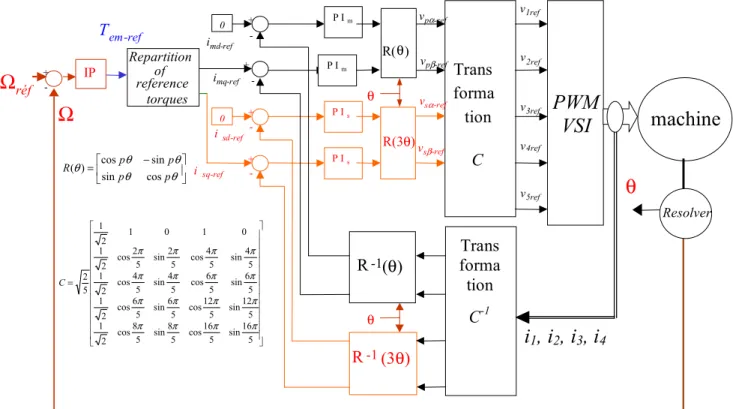
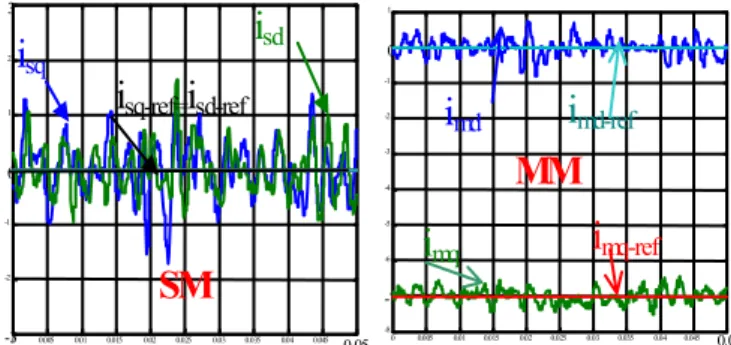
controller in the D-Q frame and the total compensation controller with integrators, we shall impose same proportional and integral action for the closed loop on the axis Q.

As an alternative to using standardized biomarker levels, some authors include sampling characteristics as covariates in regression models describing associations between

The present paper is devoted to the computation of two-phase flows using the two-fluid approach. The overall model is hyperbolic and has no conservative form. No instanta- neous

A Two-Dimensional Relaxation Scheme for the Hybrid Modelling of Gas-Particle Two-Phase Flows.. Kateryna Dorogan,

L’archive ouverte pluridisciplinaire HAL, est destinée au dépôt et à la diffusion de documents scientifiques de niveau recherche, publiés ou non, émanant des

But in fact, our results can be compared to the Multifluid approach with a first order scheme and no velocity dispersion, as this method captures naturally the effects that are