HAL Id: tel-00162118
https://pastel.archives-ouvertes.fr/tel-00162118
Submitted on 16 Jul 2007
HAL is a multi-disciplinary open access
archive for the deposit and dissemination of
sci-entific research documents, whether they are
pub-lished or not. The documents may come from
teaching and research institutions in France or
abroad, or from public or private research centers.
L’archive ouverte pluridisciplinaire HAL, est
destinée au dépôt et à la diffusion de documents
scientifiques de niveau recherche, publiés ou non,
émanant des établissements d’enseignement et de
recherche français ou étrangers, des laboratoires
publics ou privés.
Experimental study and modelling of high temperature
creep flow and damage behaviour of 9Cr1Mo-NbV
Vincent Gaffard
To cite this version:
Vincent Gaffard. Experimental study and modelling of high temperature creep flow and damage
behaviour of 9Cr1Mo-NbV. Mechanics [physics.med-ph]. École Nationale Supérieure des Mines de
Paris, 2004. English. �NNT : 2004ENMP1269�. �tel-00162118�
Collège doctoral
THESE
Pour obtenir le grade de
Docteur de l’Ecole Nationale Supérieure des Mines de Paris
Spécialité : Sciences et Génie des Matériaux
Présentée et soutenue publiquement par
Vincent Gaffard
Ingénieur de l’Institut National Polytechnique de Grenoble (ENSEEG)
Le 13 décembre 2004
Experimental study and modelling of high temperature creep flow and
damage behaviour of 9Cr1Mo-NbV steel weldments
(Etude expérimentale et modelisation, du comportement, de l’endommagement et de la
rupture en fluage à haute température de joint soudés en acier 9Cr1Mo-NbV)
Directeur et directrice de thèse: M. Jacques Besson
& Mme Anne-Françoise Gourgues-Lorenzon
Jury
M. Gunther Eggeler
Ruhr-Universität Bochum
Rapporteur
M. Helmut Klöcker
ENSMSE
Rapporteur
M. Claude Prioul
ECP
Examinateur
M. Jacques Besson
ENSMP
Examinateur
Mme Anne-Françoise Gourgues-Lorenzon
ENSMP
Examinatrice
M. Roland Piques
ENSMP
Membre invité
Mme Marie-Thérèse Cabrillat
CEA Cadarache
Membre invité
M. Sylvain Leclercq
EdF
Membre invité
M. Jean-Marc Cloué
Framatome
Membre invité
M. Jean-Christophe Brachet
CEA Saclay
Membre invité
Centre des Matériaux P.M. Fourt de l’Ecole Nationale Supérieure des Mines de Paris
BP87 91003 Evry Cedex France
« Comme un iceberg se renverse, la mathématique, globalement a viré, en début de ce siècle, au formalisme. Elle a délaissé lʹintuition. Elle a oublié lʹintuition. Elle a même, parfois, condamné lʹintuition... La ruée logique, axiomatique, formelle, ne fut pas seulement propre aux mathématiques... Le tsunami a touché tous les rivages de la mer Encyclopédie. Physiciens ou philosophes, sociologues ou biologistes, nous étions tous des formalistes. Jusquʹà la rigueur, certes, et puis, jusquʹà lʹexcès. Quand je voulais connaître une bête, je lisais un livre sur cette bête, où jamais je ne voyais la bête, jamais. Nous sommes fatigués de ne plus rien voir. Je veux voir enfin derrière ces grimoires, et brûler ces écrans de mots et de signes. Voici. Lʹintuition revient. » M. Serres Le Passage du Nord-Ouest, Les Editions de Minuit (1980)
___________________________________________________________________________________________________________
Introduction
Context: New materials for future power stations
The efficiency of all type of power plant depends on the heat transfers between the vessel and the boiler. Therefore increasing service pressure and temperature should ensure better efficiency. Pressure of 240 bar and temperature of 550°C are currently the maximum service conditions encountered in the classical fossil fuel power plants. The great challenge for the new supercritical and ultra supercritical power plants is to match service values pressure larger than 300 bar and temperature larger than 650°C. Indeed, it will lead to a better efficiency of the production of electricity with two consequences :
1. Lower production costs.
2. A positive impact on environment as CO2 emissions would be reduced by 2% if efficiency is 1% better (Note that the
electrical power generation is responsible for over 20% of the worldwide emissions of CO2).
To reach this goal, it is necessary to develop new high temperature resistant materials to replace 316 and 304 austenitic stainless steels that are the most commonly used materials for reactor vessel, primary and secondary loops in power plants. Among all materials, chromium martensitic stainless steels have been largely studied during the last three decades. Research programs have been simultaneously conducted in the United States (EPRI), Japan (EFDC) and Europe (COST 501 and 522). The objective of COST 501 and 522 (see Staubli et al 2001)) programs are service conditions of 280 bar / 600-650°C. The next European program THERMIE which has started in 1998 has the objective to reach 375 bar / 700-720°C in 2013: it essentially concerns Ni-base alloys. The objectives in terms of in-service conditions of the new generation of power plants are given in figure In.1 and as underlined by Vandstone (1998), the typical basis of the power plant design is to reach in service durations of 100,000 hours. It is admitted that the life assessment generally requires long term tests at high temperature for at least one percent of the service life (i.e. 1,000 hours for a lifetime of 100,000 hours) to ensure the extrapolation accuracy.
Market Market
Figure In.1. In service conditions in classical and future power plants (extracted from Metcalfe and Scarlin (1998))
The main advantages of the chromium ferritic and martensitic stainless steels are: 1. Good corrosion resistance.
2. Interesting mechanical properties up to 600°C thanks to the addition of several strengthening alloy elements like V, Nb or Mo.
3. Good thermal conductivity and low thermal expansion coefficient ensure good weldability of the steel. 4. A low nuclear activation energy provided Mo, Ni, Nb and V contents are limited.
5. A lower material cost than austenitic stainless steels mainly as chromium is cheaper than nickel.
2.25Cr-1Mo stainless steels were the first generation of chromium steels that have been integrated in power plants, for example as tubing material in the evaporator of Phenix. Then, many efforts have been made these 20 last years to develop new alloys starting from the first 9Cr1Mo steel (already used in petrochemical applications since the 1950’s) which exhibited limited weldability, forgeability and fracture toughness. The initial composition of the steel has then been modified in the United States with the addition of niobium and vanadium (P91/T91 steels) whereas it was chosen to increase the chromium content and to add tungsten in Japan leading to the P92/P122/E911 series. The evolution of the alloy composition as well as the corresponding predicted long term creep properties are reported in figure In.2 (see also Von Hagen and Bendick (2001), Klueh and Harries (2001), Fujita (2001) and Von Hagen and Scarlin (1998)).
Figure In.2. Progress in chromium stainless steel designs (Hald (1996))
The present study is concerned with 9Cr1Mo-NbV steels which are not the last generation of chromium steels. They are already used in power plants for boiler and steam line (see Blum and Hald (1998)) like in Lippendorf (267 bar, 550-580°C), Boxberg (267 bar, 555-578°C) and Nordjylland (290 bar – 580°C) plants. They are also candidates for structural materials for the Fast Breedor Reactor in India and for the DEMO fusion reactor that would follow the ITER reactor. Therefore, there is a strong need to predict the evolution of their metallurgical and mechanical properties for long term service exposures.
Aim of the present study
The present study has benefited from a strong financial support from Electricité de France (EdF), le Commissariat à l’Energie Atomique (CEA) and Framatome and is a part of a large research program (see Cabrillat et al (2004)). It deals with studying creep flow and damage behaviour of 9Cr1Mo-NbV base metal and weldments in the temperature range
from 450°C to 650°C. Indeed, the use of 9Cr1Mo-NbV steels as structural materials in industrial facilities implies to join
large components as can be shown in figure In.3. The most common joining method is welding. This operation leads to several changes in the mechanical properties of the resulting structure that may have dramatic influences on the creep strength.
Figure In.3. Example of the welding operation on a pipe (source www.altavista.com)
More generally, several problems can be related to the welding operation:
1. The solidification of the weld metal may lead to the formation of cracks especially for very thick components. 2. The solidification is accompanied by a metal contraction leading to stress concentrations that may be significant. As a
3. Local heating of the base metal induces phase transformations and several microstructural and mechanical properties changes in the so called heat affected zone whose thickness is not much larger than 5 mm.
One critical point in the design of 9Cr1Mo-NbV weldments is their very high sensitivity to type IV cracking (i.e. rupture in the HAZ parallel to the fusion line) in high temperature creep conditions. Six incidents of cracking and failure have yet been reported especially in the West Burton power plant in the United Kingdom after only 20,000 hours at 565°C i.e. largely under the maximum design temperature of 600°C. These incidents are reported in Shibli (2002), Brett et al (2001), Brett et al (1999), Allen et al (1999) and Middleton et al (1990). Even if Brett et al (1999) and Allen et al (1999) concluded that these incidents were probably due to incorrect heat treatment during manufacturing, they evidenced a great need to finely investigate the effects of welding on the microstructural and mechanical properties of 9Cr1Mo-NbV steel welded components. This need to predict the risk of type IV failure in 9Cr1Mo-NbV weldments is of particular importance as the steel is actually used at its maximum design temperature (i.e. 600°C) in Japan. Note also that in the synthesis of Parrot and Shibli (2004), the failure of a secondary superheater tube operating at 540°C and under an internal pressure of 8.2 MPa is reported after 63,000 hours of service.
The present study was performed in the framework of the local approach to fracture whose guideline principles are to “combine a detailed experimental analysis of the considered materials and of their specific damage mechanisms, a realistic modelling of these mechanisms and the implementation of these models into a numerical simulation of the response of the structural components under investigation” (A. Zaoui in Berdin et al (2004)).
The first part of this work (Part A) is dedicated to the description of material microstructures and general mechanical properties as they strongly determine the material creep strength. The effects of thermal ageing are especially studied as the microstructural stability is a key point in the material ability to retain its creep strength after long term exposure. Then, creep flow and damage behaviour of the base metal is analysed (Part B). Numbers of experiments, mainly creep tests, were performed at 625°C to investigate damage mechanisms and their relationships with mechanical fields. To predict creep time to failure up to 100,000 hours, a new creep model integrating coupled influences of creep flow and damage behaviour was designed. The accuracy of the extrapolation of creep results from about 1,000 hours to 100,000 hours is especially questioned. From literature data and experimental results, the model was extended to the temperature range from 550°C to 650°C. It is shown in the present manuscript that extrapolations above or below this domain may be extremely hazardous.
Special attention was then focused on determining the creep properties of the weldments (Part C). The reduction in the creep lifetime is due to the lower creep strength of part of the heat affected zone. To identify the intrinsic creep flow and damage behaviour of the weakest part of the heat affected zone, a Gleeble 1500 thermal mechanical simulator was used to obtain bulk specimens having the same metallurgical properties as this zone but on a larger volume. The new creep model used for the base metal was also used to fit on the creep response of this simulated microstructure.
Moreover, creep flow properties of the weld metal were also studied. Consequently, one model, with three different sets of parameters, i.e. for the base metal, for the weld metal and for the heat affected zone, integrating coupled influence of creep flow and damage mechanisms, were determined. Using this three-material representation, simulation of the creep response of weldments was possible (Part D). Structural effects due to mismatch in material creep properties could thus be evaluated. Finite element (FE) calculations were performed to investigate the effects of geometrical parameters (weld angle, relative proportion of each material, specimen diameter …) on the weldment creep response. The ability to use the model for design purposes was finally investigated.
For the sake of clarity, the synthesis of experimental results and descriptions of experimental techniques are given in appendices A and B. All the micrographs presented in this study were taken using the two scanning electron microscopes (the LEO 1450VP and the Field Emission Gun 200 DSM 982 Gemini) of the Centre des Matériaux of the Ecole Nationale Supérieure des Mines de Paris. Transmission micrographs were taken both at the CEA Saclay and the CEA Grenoble. All mechanical tests were carried out at the Centre des Matériaux of the Ecole Nationale Supérieure des Mines de Paris and at the Centre de recherches des Renardières of EdF. The author wishes associate to the experimental results of the present study: M. Rousselot (ENSMP), F. Grillon (ENSMP), J. Valy (ENSMP), A. Naslot (ENSMP), D. Pachoutinsky (ENSMP), Y. Rousseleau (EdF), G. Lindet (EdF), B. Brugier (Framatome), Dr. L. Guetaz (CEA), Dr. Y. Decarlan (CEA), C. Meurin (ENSMP), J. Gibier (ENSMP), G. Cassas (ENSMP), J.L. Ajzenberg (ENSMP), J. Labrousse (ENSMP) and A. Laurent (ENSMP). Dr. Roland Piques who largely contributed to the birth of this research project is also strongly acknowledged and associated to the present study. Many thanks are due to Marie-Thérèse Cabrillatand Bruno mICHEL (CEA Cadarache)? Sylvain Leclercq (EdF) and Jean-Marc Cloué (Framatome).
I’m very grateful tomy supervisors : Anne Françoise Gourgues-Lorenzon and Jacques Besson for fruitful discussions and their strong supportin experimental and theoretical developments of the present work.
References
Allen D.J., Brett S.J. (1999). Premature failure of a P91 header encap weld: minimising the risks of additional failures.
Proceedings of the conference on case histories in failure investigation – Milan. 133-143.
Berdin C., Besson J., Bugat S., Desmorat R., Feyel F., Forest S., Lorentz E., Maire E., Pardoen T., Pineau A., Tanguy B. (2004). Local approach to fracture. Edited by J. Besson in les presses de l’école des mines de Paris. Préface. 9-10.
Blum R., Hald J. (1998). Benefit of advanced steam power plants. Materials for advanced power engineering - 6th Liege
Conference. 1009-1016.
Brett S.J., Allen D.J., Pacey J. (1999). Failure of a modified 9Cr header endplate. Proceedings of the conference on case histories
in failure investigation – Milan. 873-884.
Brett S.J. (2001). Identification of weak thick section modified 9Cr forgings in service. Proceedings of the Swansea creep
conference. CDRom.
Cabrillat M.T., Reytier M., Sauzay M., Mottot M., Gaffard V., Seran J.L., Billot P., Riou B. (2004). Studies on mechanical behavior of mod. 9Cr-1Mo steel - CEA R&D program. HTR 2004 conference - Beijing China.
Fujita T. (2001). Advances in 9-12%Cr heat resistant steels for power plants. Advances in materials technology for fossil power
plants – Edited by Viswanathan R. 33-65.
Hald J. (1996). Metallurgy and creep properties of new 9-12%Cr steels. Steel research. 67(9). 369-374.
Klueh R.L. and Harries D.R. (2001). High chromium ferritic and martensitic steels for nuclear applications. American
Society for Testing Materials
Metcalfe E., Scarlin B. (1998). Advanced high efficiency power plant. Materials for advanced power engineering - 6th Liege
Conference. 33-51.
Middleton C., Metcalfe E. (1990). A review of laboratory type IV cracking data in high chromium ferritic steels. Paper
C386/027 published in ImechE proceedings – London.
Parrot A., Shibli A. (2004). Performance du P91 et des autres aciers martensitiques à 9%Cr : Expérience industrielle et en laboratoire. EdF report n°HT-26/02/006/A. In French (Private communication).
Shibli I.A. (2001). Overview of the HIDA project. International journal of pressure vessels and piping. 78. 729-735.
Staubli M., Mayer K.H., Kern T.U., Vandstone R.W., Hanus R., Stief J., Schonfeld K.H. (2001). Cost 522 – Power generation into the 21st century; advanced steam power plant. Advances in materials technology for fossil power plants – Edited by Viswanathan R. 15-32.
Tavassoli A.A.F (1998). Materials design data for fusions reactors. Journal of nuclear materials. 258-263. 85-96.
Vandstone R.W. (1998). Alloy design and microstrutcural control for improved 9-12%Cr power plants steels. Materials for
advanced power engineering - 6th Liege Conference. 1035-1047.
Von Hagen I., Bendick W. (2001). Creep resistant ferritic steels for power plants. Niobium science and technology –
proceedings of the international symposium Niobium 2001. 753-776.
Von Hagen I., Scarlin B. (1998). Advanced high efficiency power plant. Materials for advanced power engineering - 6th Liege
Conference. 33-51.
Viswanathan R., Bakker W.T. (2000). Materials for boilers in ultra supercritical power plants. Proceedings of the
Contexte : de nouveaux matériaux pour les futures unites de production d’électricité
L’efficacité des unités de production électrique dépend intimement des pertes énergétiques lors des différents transferts de chaleur. C’est pourquoi, une augmentation des pressions et températures admissibles en service devraient assurer une amélioration non négligeable du rendement des unités de production électrique. Une pression de 240 bars et une température de 550°C sont actuellement les conditions de service dans les centrales thermiques classiques. Le développement de nouvelles unités de production dites supercritiques et ultra-supercritiques dont la pression et la température en service visées sont respectivement de 300 bar et 650°C est un objectif ambitieux. De telles unités présenteraient cependant des rendements bien meilleurs avec pour conséquence :
3. Une diminution des coûts de production.
4. Un impact positif sur l’environnement avec une réduction de 2% des émissions de CO2 pour une augmentation de
1% du rendement.
Pour atteindre un tel objectif, il est apparu nécessaire de développer de nouveaux matériaux résistants aux sollicitations haute température pour remplacer les aciers inoxydables austénitiques type 304 et 316 et les aciers ferritiques type 1Cr-Mo ou 2.25Cr-1Cr-Mo qui sont actuellement des matériaux couramment utilisés. Parmi les matériaux pressentis, les aciers martensitiques à 9-12% de chrome sont les plus largement étudiés depuis les trente dernières années. De nombreux programmes de recherches ont été entrepris aux Etats Unis (EPRI), au Japon (EFDC) et en Europe (COST 501 et 522). L’objectif des programmes COST 501 et 522 (cf. Staubli et al 2001)) était d’identifier les matériaux susceptibles de résister aux sollicitations de fatigue et fluage pour des conditions de service de 280 bar / 600-650°C. Le projet européen suivant : THERMIE qui a débuté en 1998 est encore plus ambitieux puisque les conditions de service visées sont de 375 bar / 700-720°C à l’horizon 2013.
Les objectifs des différents programmes de recherche en termes de conditions de service sont résumés figure In.1. Comme l’indique Vandstone (1998), le critère de résistance en fluage retenu est la contrainte maximale admissible permettant d’atteindre une durée de vie de 100000 heures en fluage. La pratique courante est de réaliser des essais en laboratoire avec des temps d’essais beaucoup plus courts à partir desquels les prédictions de durée de vie à 100000 heures sont établies (i.e. 1000 heures d’essais en laboratoire pour prédire la durée de vie à 100000 heures).
Les avantages des aciers martensitiques inoxydables au chrome sont nombreux : 6. Une bonne résistance à la corrosion.
7. De très bonnes propriétés mécaniques jusqu’à 600°C grâce à une optimisation de la composition en V, Nb ou Mo. 8. Une bonne conductivité thermique et un faible coefficient d’expansion thermique (Bonne soudabilité).
9. Une faible sensibilité à l’irradiation si les teneurs en Mo, Ni, Nb et V sont limitées.
10. Un coût très inférieur à celui des aciers austénitiques (Prix du chrome inférieur celui du nickel).
Les aciers inoxydables 1Cr-Mo et 2.25Cr-1Mo constituent les deux premières générations d’aciers inoxydables au chrome qui sont déjà utilisés comme matériaux de structure dans les centrales thermiques du parc EDF. Ces trente dernières années, de nombreux efforts ont été consacrés à l’optimisation de la composition des aciers 9Cr1Mo afin d’améliorer leur résistance mécanique mais aussi leur soudabilité. La composition initiale du matériau a ainsi été modifiée aux Etats-Unis avec l’optimisation de la teneur en niobium et vanadium (aciers P91/T91) tandis qu’il a été choisi au Japon d’augmenter la teneur en chrome et d’ajouter du tungstène (aciers P92/P122/E911). Les évolutions de la composition chimique de l’acier et la tenue en fluage des nuances ainsi obtenues sont répertoriées figure In.2 (voir aussi Von Hagen et Bendick (2001), Klueh et Harries (2001), Fujita (2001) et Von Hagen et Scarlin (1998)).
Notre étude concerne les aciers 9Cr1Mo-NbV qui ne sont pas la dernière génération des aciers au chrome. Ils sont notamment déjà largement utilisés dans les circuits vapeurs (cf. Blum and Hald (1998)) d’unités de production comme à Lippendorf (267 bar, 550-580°C), Boxberg (267 bar, 555-578°C) et Nordjylland (290 bar – 580°C). Par conséquent, il est important d’être capable de prédire l’évolution des propriétés mécaniques et métallurgiques de ces alliages pour des sollicitations de fluage longue durée.
Objectif de l’étude
Ce travail de thèse a été financé par Electricité de France (EdF), le Commissariat à l’Energie Atomique (CEA) et Framatome. Il s’inscrit dans un vaste programme de recherche (cf. Cabrillat et al (2004)). Il s’intéresse au comportement,
à l’endommagement et à la rupture en fluage de l’acier 9Cr1Mo-NbV et de ces produits soudés dérivés dans la gamme de température 450 - 650°C. En effet, l’utilisation des aciers 9Cr1Mo-NbV comme matériaux de structure sur les
installations industrielles requiert l’assemblage de composants de grande taille comme le montre la figure In.3. La méthode d’assemblage la plus couramment utilisée est le soudage. Cette opération conduit à des modifications microstructurales qui peuvent avoir une influence très importante sur les propriétés mécaniques et plus particulièrement la tenue en fluage.
D’une manière générale, l’opération de soudage peut induire plusieurs types de problèmes:
4. la solidification du métal d’apport peut conduire à la formation de criques notamment pour les produits épais. 5. Le retrait consécutif à la solidification du métal déposé engendre des contraintes résiduelles importantes. Un
traitement de détensionnement post-soudage est ainsi quasi-systématiquement réalisé.
6. L’échauffement local du métal de base dans la Zone dite Affectée Thermiquement (ZAT) induit des transformations de phases qui s’accompagnent de modifications plus ou moins importantes de la microstructure et des propriétés mécaniques.
Le point le plus critique des assemblages soudés en acier 9Cr1Mo-NbV est leur très grande sensibilité à la rupture de type IV (i.e. rupture dans la ZAT parallèlement à la ligne de fusion) dans les conditions de fluage à haute température. Six incidents majeurs ont déjà été reportés comme dans l’unité de production électrique de West Burton en Angleterre où la rupture d’un assemblage soudé a été constatée après 20000 heures de fonctionnement à 565°C c’est à dire pour une température très inférieure à 600°C qui était la température d’utilisation maximale conseillée. Ces incidents sont décrits dans Shibli (2002), Brett et al (2001), Brett et al (1999), Allen et al (1999) et Middleton et al (1990). Même si Brett et al (1999) et Allen et al (1999) ont conclu que ces incidents étaient probablement dus à un mauvais traitement thermique lors de la fabrication des composants, ils ont mis en évidence la nécessité de comprendre plus finement les effets du soudage sur la tenue en fluage des aciers 9Cr1Mo-NbV.
Notre étude a été réalisée dans le cadre de l’approche locale de la rupture qui combine une analyse expérimentale détaillée des matériaux considérés, de leurs propres mécanismes d’endommagement, une modélisation représentative de ces mécanismes et l’implémentation de ces modèles pour la simulation numérique de structures réelles.
La première partie de ce travail (Partie A) est dédiée à la description des microstructures des matériaux et de leurs propriétés mécaniques car elles influencent fortement la tenue en fluage. Les effets de vieillissements thermiques statiques sont également étudiés car la stabilité microstructurale est représentative de la capacité du matériau à conserver sa résistance mécanique en fluage pour des temps d’exposition longs à haute température.
Ensuite, le comportement et l’endommagement de fluage du métal de base sont étudiés (Partie B). De nombreux essais mécaniques (principalement de fluage) ont été réalisés à 625°C pour identifier les mécanismes d’endommagement. Pour prédire la durée de vie en fluage à 100000 heures, un nouveau modèle de fluage intégrant plusieurs mécanismes de déformation et d’endommagement a été formulé. La validité de l’utilisation de résultats d’essais de laboratoire n’excédant pas 1000 heures voir 10000 heures pour prédire des durées de vie à 100000 heures est en particulier remise en cause. A partir de données de la littérature et de résultats expérimentaux, le modèle a pu être utilisé dans la gamme de température 550 - 650°C. Il est montré dans ce manuscrit que des extrapolations en dehors de ce domaine de température peuvent être dangereuses (Modification des mécanismes physiques de déformation et d’endommagement).
Une attention toute particulière a été apportée à la détermination de la résistance en fluage des joints soudés (Partie C). Il est notamment mis en évidence une réduction significative de la résistance en fluage qui est attribuée à la mauvaise tenue de la ZAT intercritique en fluage. Pour déterminer les propriétés de fluage intrinsèques de cette ZAT faible, un simulateur thermo-mécanique Gleeble 1500 a été utilisé pour simuler sur de larges volumes la microstructure de cette ZAT faible. Le nouveau modèle de fluage identifié pour le métal de base a aussi été utilisé pour représenter la réponse en fluage de la microstructure simulée.
Les propriétés intrinsèques du métal d’apport ont également été déterminées. Ainsi à partir d’un seul modèle intégrant plusieurs mécanismes de déformation et d’endommagement, trois jeux de paramètres différents i.e. pour le métal de base, pour le métal d’apport et la zone affectée thermiquement ont été identifiés. A partir d’une représentation à trois matériaux, la simulation de la réponse des assemblages soudés à la sollicitation de fluage a ainsi été possible (Partie D). Nous avons notamment pu, à partir de ces simulations, évaluer les effets de structure induits par les hétérogénéités de comportement et de résistance au fluage. Les calculs éléments finis ont également permis d’étudier l’effet de différents paramètres géométriques (angle de la soudure, taille des éprouvettes testées, largeur de ZAT …). L’aptitude du modèle à prédire la durée de vie en fluage de composants industriels a également été démontrée.
___________________________________________________________________________________________________________
Table of contents
(Table des matières)
Part A. Materials
Chapter A.I. Base metals
Chapter A.II. Weldments
Part B. Creep flow and damage mechanisms of 9Cr1Mo-NbV steels at high temperature: Experiments and Modelling
Chapter B.I. State of the art.
Chapter B.II. Experimental investigations of creep mechanisms and cavitation processes in P91 steel at 625°C (smooth round specimens).
Chapter B.III. Modelling creep mechanical and damage behaviour of the P91 steel at 625°C: “Creep failure
model of a tempered martensitic stainless steel integrating multiple deformation and damage mechanisms”. V. Gaffard, J. Besson, A.F. Gourgues-Lorenzon. Submitted to international journal of fracture.
Chapter B.IV. Validation of the model: Ability of the model to represent creep tests on CT and plate notched specimens.
Chapter B.V. Formulation and use of a locally coupled version of the model.
Chapter B.VI. Creep flow and damage behaviour of the T91 steel at 450°C and 550°C.
Part C. Creep flow and damage mechanisms of 9Cr1Mo-NbV weldments at high temperature. Experimental evaluation and modelling of creep flow and damage behaviour of the weakest area of weldments
Chapter C.I. State of the art
Chapter C.II. Comparison between creep flow and damage behaviour of the P91 base metal and the WJP91 weldment at 625°C: “High temperature creep flow and damage properties of 9Cr1Mo-NbV steels: base metal
and weldment” V. Gaffard, A.F. Gourgues-Lorenzon and J. Besson. Intended to be submitted to Nuclear
engineering and design.
Chapter C.III. Creep flow and damage properties of the weakest area of the WJP91 weldment at 625°C:
“High temperature creep flow and damage properties of the weakest area of 9Cr1Mo-NbV steel weldments”, V. Gaffard, A.F. Gourgues-Lorenzon and J. Besson. Intended to be submitted to ISIJ international.
Chapter C.IV. Modelling creep flow and damage behaviour of the weakest area of the WJP91 weldment:
“Modelling high temperature creep flow and damage properties of the weakest area of 9Cr1Mo-NbV steel weldments”, V. Gaffard, J. Besson. and A.F. Gourgues-Lorenzon. Intended to be submitted to engineering fracture
mechanics.
Part D. Modelling creep flow and damage behaviour of weldments
Chapter D.I. State of the art.
Chapter D.II. Modelling coupled creep flow and damage behaviour of weldments: “Modelling high
temperature creep flow and damage behaviour of 9Cr1MoNbV steel weldments”. Intended to be submitted to
european journal of mechanics.
Chapter D.III. Predictions of creep lifetime of cross-weld specimens by means of elasto-viscoplastic calculations and the use of a rupture criterion in post-calculation.
Chapter D.IV. Modelling creep flow and damage behaviour of the WJT91 weldment at 450°C and 550°C.
Chapter D.V. Use of the model to predict creep lifetime of welded components for industrial applications.
Conclusions and further works
17 21 49 67 71 103 117 145 155 161 175 179 188 205 227 249 253 269 289 297 307 321
Part A
Materials
(Matériaux)
Introduction
This first part is dedicated to the description of the materials of the study which consist in two base metals of type 9Cr1Mo-NbV steels and two weldments that are studied in terms of metallurgical and general mechanical properties. Effects of ageing are also explored.
In the following:
1. P91 and T91 will refer to base metals.
2. WJP91 and WJT91 will refer to weldments respectively corresponding to the P91 and the T91 base metal. 3. WMP91 and WMT91 will refer to weld metals respectively used for the WJP91 and the WJT91 weldments.
Attention is first focused on base metals (chapter A.I) which are tempered chromium martensitic stainless steels. Alloy composition and thermal treatment characteristics are described. The presentation of the resulting microstructure is made throughout optical, scanning electron microscope (SEM) and transmission electron microscope (TEM) observations. A description of inclusions and of the precipitation behaviour is also included.
Then, evaluation of general mechanical properties throughout tensile tests at high temperature is presented. Strain rate effects on tensile response are in particular explored. The last part about base metals is dedicated to the study of thermal ageing. T91 and P91 steels were respectively submitted to 450°C, 550°C and 550°C, 625°C thermal ageings for 1,000 hours, 5,000 hours and 10,000 hours. Identification of second phase particles and measurements of the evolution of the average particle size, using carbon extraction replicas, were done. TEM and electron backscattered diffraction (EBSD) investigations were also performed to explore the microstructural changes during thermal ageing.
Attention is then focused on welded components (chapter A.II). The welding procedures, the composition and the properties of the weld metals are described. Some recommendations to ensure the integrity of the weldments are also given. The main point that is explored is the modification of metallurgical and mechanical properties in the so called heat affected zone of weldments. This heat affected zone is classically divided into three main parts related to local phase transformations. Hardness measurements, SEM and TEM investigations are performed to characterise the resulting microstructures.
Contents
Chapter A.I. Base metal
Chapter A.I. Base Metal
1. Alloy composition and general feature of the microstructure
The P91 steel was supplied by Mannesmann and Vallourec as a seamless pipe of 295 mm in outer diameter and 55 mm in thickness. The T91 steel was supplied by Creusot Loire as a plate of 150 mm in thickness. The chemical composition of the steels of this study is shown in table A.I.1.
C Si Mn P S Al Cr Ni Mo V Nb N
P91 0.09 0.31 0.41 0.014 0.005 0.016 8.56 0.26 0.92 0.21 0.065 0.042
T91 0.105 0.240 0.44 0.008 0.00016 0.013 8.41 0.08 0.95 0.25 0.08 0.033
Table A.I.1. Chemical composition of the steels examined in the present study (wt %)
One should notice several differences between P91 and T91 alloys composition as nuclear specifications require a strict controll of segregating elements like P, S or Si. Some comments can be done about roles of elements:
1. Cr is added to ensure a good resistance to corrosion and good mechanical properties.
2. Nb,V restrict the austenite grain growth during austenitization and have a strengthening effect by precipitation of MX particles during tempering.
3. Mo is added for solid solution strengthening.
4. P and S contents are strictly controlled as they are potentially segregating elements at grain boundaries.
5. Ni is detrimental by forming a brittle Fe rich phase but also considerably lowers the Ac1 temperature so that its
addition must be strictly controlled.
For the sake of completeness, the synthesis of Maruyama et al (2001) about the role of elements is given in figure A.I.1. where the role of the newly used alloy elements as W or Re, are also reported (Note that “D” designates the austenie grain size in figure A.I.1).
Moreover, the balance between all elements must be controlled to avoid δ ferrite formation. Schneider’s sketch and equivalent Ni and Cr percentages formulae are often used to predict possible presence of δ ferrite. For chromium steels, equivalent Ni and Cr percentages are given by:
C % 30 N % 25 Cu % 3 . 0 Mn % 5 . 0 Co % Ni % Ni
%eq = + + + + + (in wt %) (eq. A.I.1)
W % 75 . 0 Ti % 5 . 1 Nb % 75 . 1 V % 5 Al % 5 . 5 Mo % 5 . 1 Si % 2 Cr % Cr
%eq = + + + + + + + (in wt %) (eq. A.I.2)
where the compositions are in wt%. The calculated values of %eqNi and %eqCr are reported in the Schneider (1960)
diagram of figure A.I.2 established by Orr and DiFrancesco (1993) from a study on 9Cr1Mo-NbV steels. It shows that no δ ferrite should appear during P91 and T91 steels elaboration. This prediction was experimentally confirmed as no δ ferrite was detected in any of the two base metals of this study by scanning electron microscopy (SEM) investigations.
% chrome équivalent % N ic kel é quiva le nt 10 11 12 13 14 3 4
5
6Figure A.I.2. Schneider diagram established by Orr and Difrancesco for 12CrMoV type steels
Evaluation of P91 and T91 %Nieq and %Creq
Note also in figure A.I.2 that the steels of the study are within the specifications limits of the ASTM with %Creq ≈ 11.8%
and %Nieq = 4.2 %, and also that it exists chemical compositions of steel 91, set within the ASTM ranges, that could result
in a material containing up to 10% of δ ferrite for %eqCreq > 12.5%.
The two steels are martensitic chromium stainless steels obtained after normalising at high temperature and rapid quench followed by a tempering treatment. The resulting microstructure is a lath martensite arranged in packets in prior austenite grain boundary (figure A.I.3). Microstructure of the steel is also characterised by a high dislocation density and the precipitation of numbers of carbides of mainly M23C6 type at grains boundaries (preferentially at lath interfaces and
dislocations: see Jones et al (1991)) but also precipitates of type MX which are both located at prior austenite grain boundary and along dislocations in the matrix of martensite lath (see Kaneko et al (2004) and Taneike et al (2004)). Although primary carbides, contain a balance of Nb and V, it was shown by Suzuki et al (2003) that a two phase separation of primary MX into V rich and Nb rich precipitates occurs during tempering. This point is also confirmed by the present study. Taneike et al (2004) have also shown that MX precipitates along grain boundaries contain more vanadium and less niobium than these found within lath martensite. Note finally that in the steels of the present study, no M2X precipitates were detected.
10 µm
a b
Figure A.I.3. (a) Sketch of P91 steel microstructure extracted from Masuyama (2001) (b) Optical micrograph after villela etching
Inclusion characterisation:
The volume fraction of inclusions is said to be very low in 9Cr1Mo-NbV steels and Zhang et al (2000) have reported that it does not exceed 5 .10-4. In the present study, no measurement of the volume fraction of inclusions was carried out but
X-ray dispersive wavelength spectroscopy analysis, using a Castaing electron microprobe, was performed. Results of the study are reported in table A.I.2 (Note that only qualitative results are given as the small size of the inclusion did not allow to determine the exact chemical compositions of inclusions).
Material Inclusion type Size Reference
P91 Al, Mn, O 2 µm – 3 µm Soussan (2000)
T91 Al, Cu, Mn, O / SiO2 1 µm – 2 µm This study
Table A.I.2. Inclusions in base metal
Formation of these inclusions is mainly due to the elaboration process. Indeed, desoxidation is necessary as oxygen that is trapped during the solidification step may lead to the formation of a high number of cavities. Therefore, elements like Si, Al or Mn which have a strong affinity for oxygen are added. As it has already been underlined by Bush (2001) this step is critical because these elements, especially Al, have also a great affinity for nitrogen and may avoid carbonitrides
of type MX or M2X precipitation during tempering. Note also that SiO2 and Mn2O3 inclusions can come from the
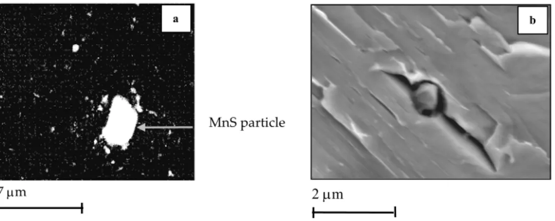
refractory materials which are in contact with the steel in the liquid state. No MnS particles were detected which is a
good point as they would lower the impact toughness but it also shows that the sulphur probably segregates at grain boundaries. As optical and SEM observations confirm a very low inclusion content, no quantification of the area fraction of inclusion was performed. It will also be shown later on, that inclusions play a negligible role in the high temperature creep cavitation process for the steel of the study.
2. Heat treatments and resulting properties
The determination of the prior austenite grain size is quite difficult. Several techniques are proposed especially by Brachet (1991) who proposed both a technique based on a two step cooling (a dwell near 600°C is especially performed) which promotes the formation of pro-eutectoid ferrite at austenite grain boundaries and a use of a special etching reagent (Béchet-Beaujard = saturated aqueous picric acid and 1% of surfactant sodium tridecylbenzene sulfonate). A technique of thermal etching is also proposed by Garcia de Andres et al (2001). It consists in heating a polished sample to the austenitization temperature under vacuum. It follows that grooves form at austenite grain boundaries due to surface tension effects.
In the present study an etching reagent (100 ml of water solution saturated in picric acid + 10 ml of Xylen + 5 ml of Photoflo produced by Kodak®), already successfully used by Schacht and Richter (1998) for a 21/4Cr steel, was used. The
size of the martensitic packet was determined after Villela etching of the material microstructure. The determination of the average austenite grain and packet sizes were done from the image analysis of optical micrographs using a public domain analysis software Scion® (see appendix B.H for a finer description of the technique). In both cases, the average
grain size was determined from the analysis of more than four hundred grains. The size of the lath martensite i.e. their thickness was determined from transmission electron microscopy (TEM) investigations.
To study the precipitation state, second phase particles were extracted on carbon replicas. The procedure described in the following is largely used in the present study:
1. Mechanical grinding and then polishing with diamond paste up to 1 µm.
2. Villela etching: 100 ml methanol, 5 ml hydrochloric acid and 1g picric acid (For information, note that another etching reagent is proposed by Grobner and Hagel (1980) and Vitek et al (1983) who recommended the use of a 10 ml HCl, 1 ml tartric acid and 100 ml methanol for extraction).
3. Carbon deposition under vacuum (The carbon layer deposed on the specimen surface is of few hundreds nanometers in thickness).
4. Extraction in Villela and cleaning in methanol before deposition on 3 mm diameter copper grids.
In a second step, the same carbon extraction replicas were observed with the field emission gun scanning electron microscope (FEG-SEM) of type Gemini DSM 982. The X-ray dispersive energy spectroscopy (EDS) facility was used to identify the chemical composition of the second phase particles. Moreover image analysis could be performed on SEM micrographs and then, using the Scion® public domain image analysis software the average particles sizes were determined from the analysis of more than four hundred particles. Finally, hardness measurements were done as a first characterisation of the steel mechanical properties. The corresponding characteristics of P91 and T91 microstructures are given in table A.I.3.
Material Normalising Quenching Tempering Grain sizes (Optical and TEM
observations) Vickers hardness HV 0.5 Precipitates (Carbon extraction replica) P91 1065°C (1h00) Air 765°C (2 h) PAG = 90 – 100 µm Packet = 30 – 40 µm Lath = 0.4 – 1.0 µm 230 M23C6 (90 - 100 nm) MX (10 - 20 nm) T91 1070°C (4h30) Water 765°C (6h45) + 750°C (15h18) PAG = 100 – 120 µm Packet = 50 – 60 µm Lath = 1.0 – 2.0 µm 215 M23C6 (130 - 140 nm) MX (10 - 20 nm)
Table A.I.3. Characteristics of the steels examined in the present study
The evolution of the austenitic grain size dependence on normalising temperature and time has been described by Barcelo and Brachet (1994). They found that the mean diameter of the austenite grain followed:
n moy Kt D = where − = RT E exp K a 0 K (eq. A.I.3)
with the activation energy Ea = 113 ±12 kJmol-1, K0 = 1 ms-0.13 and n = 0.13. This formula was used to compare calculated
and experimentally measured austenite grain sizes. Good agreement was found between measured and calculated values. The model gives: Dmoy, calc = 110 µm for 1h at 1065°C and for 4h30 at 1070°C: Dmoy, calc = 140 µm, which corresponds
to values of grain size slightly higher than those experimentally measured.
One should notice that the T91 steel was subjected to two tempering treatments. The second one is currently performed on welded components. A double tempering treatment was also carried out on several P91 base metal specimens (765°C 2h + 760°C 2h ). It could then be ensured that, despite a decrease in measured hardness at room temperature, the steel exhibits similar creep properties after one or two tempering treatments.
It is also very interesting to determine the phase transformation points and their relative position in comparison with temperatures of thermal treatments. To do so, dilatometric tests were performed on small cylindrical specimens (10 mm in length and 3.0 mm in diameter) at low heating rates respectively 1.0 °C s-1 and 0.5 °C s-1. They consisted in a heating at
a constant rate up to 1000°C immediately followed by a rapid helium cooling in order to induce the martensitic transformation (The maximum temperature of 1000°C was chosen imposed by the specifications of the furnace used for these experiments). The results are given in table A.I.4.
Material Rates Transformations Start End Austenitic Ac1 = 852 °C Ac3 = 888 °C P91 steel Martensitic Ms = 395°C Mf = 287 °C Austenitic Ac1 = 840 °C Ac3 = 890 °C T91 steel 1.0 °C s-1 * 60 °C s-1 ** Martensitic Ms = 402 °C Mf = 306 °C Austenitic Ac1 = 849 °C Ac3 = 890 °C P91 steel Martensitic Ms = 383°C Mf = 295 °C Austenitic Ac1 = 854 °C Ac3 = 901 °C T91 steel 0.5 °C s-1 * 60 °C s-1 ** Martensitic Ms = 404 °C Mf = 308 °C
Table A.I.4. Phase Transformation points for the base metals (* = heating, ** = cooling)
The positions of Ac1 and Ac3 temperatures are quite similar for the two steels. Ac1 is also 100°C higher than the tempering
temperature which should ensure no significant formation of austenite during tempering. The measured values of Ms
can be compared with the results given by the formula proposed by Beres et al (2001) from a study on 350 types of martensitic stainless steels:
Cu 21 ) Si 5 . 1 W V Mo Cr ( 5 . 9 Mn 8 . 7 Ni 27 C 2 . 4 C 210 454
Ms= − + − − − + + + + − (in wt%) (eq. A.I.4)
The calculated value of Ms (≈ 375°C) is lower than the measured ones. This difference can be explained by the non
dissolution of existing precipitates which leads to lower carbon and chromium contents in the solid solution both because no dwell at the austenitising temperature was done and because the normalising temperature was maybe too low especially to dissolve all MX precipitates. Moreover, Ms is higher in T91 than in P91 steel, probably because carbides
are larger in size in the T91 steel and are consequently more difficult to dissolve.
An experiment of differential scanning calorimetry was also carried out to determine the temperature of M23C6 carbides
dissolution. The event was unfortunately not observed but the Curie temperature could be determined as TCurie = 760°C.
Attention was then focused on heat treatments as materials properties strongly depend on them. Normalising temperature must not be too high for two reasons:
1. To avoid precipitation of δ ferrite that is very harmful for creep strength .
2. To avoid growth and coarsening of the austenite grain. Note that Orr et al (1993) experimentally evidenced that the coarsening of austenite grain starts at 1125°C. They also showed that for normalising at 1050°C or 1100°C and up to 24 hours, the austenite grain only slightly coarsen and confirms by TEM investigations that part of Nb(C,N) and VN carbides remains undissolved at 1050°C - 1100°C.
However, a normalising temperature as high as possible is necessary to dissolve main parts of primary carbonitrides. As a matter of fact normalising conditions must be carefully chosen. To obtain martensitic structure during quench, cooling rates must be up to 20°C per hours (Klueh and Harries (2001)). The martensite transformation is not diffusive as it occurs by shear of prior austenite. In its pioneering work, Kelly (1965) has distinguished two shear systems:
System I: (110)A [1-11]A ⇔ (112)M [11-1]M
System II: (111)A [1-21]A ⇔ (101)M [10-1]M (A = Austenite, M = Martensite)
However both theory and observations have largely evolved. The habit plane of the lath martensite is not well
determined: (557)γ or (223)γ according to Sandwick and Wayman (1983). Laths organisation also depends on carbon
weight percentage which was studied by Maki et al (1980). For wt %C < 0.2 (i.e. for P91 and T91 steels), laths of same orientations are gathered in packets. It is obviously confirmed by microstructural observations of the steels of the present study (see figure A.I.2). The resulting microstructure has, in fact, a very complex crystallography. Morito et al (2003) have carefully described the lath morphology and crystallography. The orientation relationships between lath martensite and austenite nearly matched one of the 24 Kurdjumov and Sachs (1930) orientation relationships. The 24 K.S. variants can be divided into fourth categories of 6 variants depending on the four main planes orientation between austenite and martensite:
1. (111)γ // (011)α‘ 2. (1-11)γ // (011)α‘ 3. (-111)γ // (011)α‘ 4. (11-1)γ // (011)α‘
Packets are characterised by lath that have the same plane parallel relationship (i.e. one of the fourth previous). Blocks which corresponds to laths of single variants are sometimes distinguished and Morito et al (2003) deduced from TEM and EBSD investigations that the 6 blocks of all variants are randomly distributed in packets.
The particularity of the quench martensite is to be very hard (HV 0.5 up to 400) but with a low ductility level and a low impact toughness (see Materkowski and Krauss (1979)). Consequently, performing a tempering treatment which softens martensite but increases mechanical strength is necessary. The tetragonality of the martensite crystal structure is given by: ss ] C [ 045 . 0 000 . 1 a c= + (eq. A.I.5) (see also figure A.I.4) therefore, when all the carbon is in the solid solution, the tetragonality of the crystal structure, c/a = 1.004 for the P91 steel and c/a= 1.0047 for the T91 steel. The ratio c/a is nearly equal to 1.0 which means that the martensite crystal structure of the studied steels is nearly body-centred-cubic like ferrite. This crystallography particularly increases the sensitivity of the microstructure to softening mechanisms such as recovery or recrystallisation.
Carbon content (wt%) C rys ta l la ttic e pa ra me te rs a & c
Body centred cubic tetragonal
Figure A.I.4. Effect of carbon content on the structure of the martensite
The evolution of the microstructure from the quench state (i.e. high dislocation density martensite over-saturated in carbon and no precipitates) strongly depends on the temperature of the tempering heat treatment (see Shantsky et al (2000)):
1. In the temperature range between 450°C and 500°C, penny shaped M2X particles precipitates.
2. In the temperature range between 500°C and 550°C, the precipitation of carbides of type M7C3 occurs and coarsening
of M2X is reported.
3. For temperatures higher than 550°C: M7C3 carbides and M2X precipitates are replaced by MX precipitates and M23C6
carbides. Moreover low angle boundary configurations start to form (i.e. recovery proceeds).
4. For temperatures higher than 650°C, carbide coarsening starts and is accompanied by the formation of subgrains. 5. For temperatures higher than 750°C, the recovery of the lath martensite into equiaxed subgrains but also carbide
coarsening largely occur. It is reported that for tempering times larger than one hour, all the carbon initially in solid solution is precipitated into M23C6 carbides.
As can be shown in table A.I.3, 9Cr1Mo-NbV steels are mainly submitted to high temperature tempering (> 750°C) on which attention will be focused in the following. During the high temperature tempering treatment (>750°C), the precipitation of carbides occurs following the sequence described by Laha et al (2000) and Vitek and Klueh (1983). Their precipitation is said to be un coherent or semi coherent with the matrix (Cadek et al (1997)):
6 23 3 7 3C M C M C Fe → → (eq. A.I.6)
This sequence is confirmed by Bjarbo and Hattestrand (2001) who performed thermodynamical calculations to follow nucleation and growth of M23C6 and M7C3 particles. Their calculations show that the dissolution of M7C3 occurs after 400s
at 750°C. Sometimes, the precipitation of M6C, M7C and M3C carbides is reported but Andrews (1972) have concluded
that for 9Cr1Mo steels only M23C6 precipitation occurs. Note also that Jones et al (1991) indicated the formation of a Cr2C
phase preceding that of M23C6 carbide. Another precipitation sequence is reported by Robson and Bhadhesia (1997a and
6 23 2 6 23 2 3 2 3C M X M C M X M C M X M C M + → + + → + (eq. A.I.7)
From experimental results, one should assume that the sequence reported by Robson and Bhadhesia (1997a and 1997b) does not well describe the precipitation in P91 and T91 steels during tempering > 750°C as rather MX than M2X particles
were experimentally detected in the tempering state (see also Okamura et al (1996)). The proposed precipitation sequence for tempering at temperatures larger than 750°C is as follows:
6 23 6 23 2 3 2 3C M X M C M X M C MX M C M + → + + → + (eq. A.I.8)
Note also that as shown by Shantsky and Inden (1997) the presence of molybdenum was evidenced in M23C6 carbides.
Moreover, the MX precipitates, which are generally of type Nb(C,N) or V(C,N), are very stable. They only dissolve at very high temperature (larger than 1100°C) as shown in figure A.I.5a and A.I.5b.
0.1 0.2 0.3 0.4 0.05 0.1 V ( w t % ) N (wt %) b a P91 steel T91 steel
Figure A.I.5. Solubility of Nb(C,N) and VN in 9Cr1Mo-NbV steels from Otoguro et al (2000) and Orr and Di Francesco (1993) (The solubility limit in the P91 and the T91 steel are also reported)
The solubility curves given in figure A.I.5 have been determined by Otoguro et al (2000) and Orr and Di Francesco (1993). Dutta and Palmiere (1998) gave the following expression for Nb(C,N) solubility in wt%:
[ ]
T 6700 06 . 2 N 14 12 C Nblog + = − (eq. A.I.9)
The equation A.I.9 was modified by Klueh and Harries (2001) to take into account interactions between carbon, nitrogen and chromium:
[ ]
e e [Cr] 2 1 T 6700 06 . 2 N 14 12 C Nb log Cr N Cr C + − − = + Cr (eq. A.I.10)[ ][ ]
V N 5.2 10500T e [Cr]log = − − N (eq. A.I.11)
with: 0.017log(T) T 8 . 145 056 . 0 e and T 180 09 . 0 e Cr N Cr C = − =− − +
Other parameters than the tempering temperature strongly influence the evolution of the microstructure. Parameswaran et al (1996) studied both the effect of the cooling rate and the effect of the tempering time on carbide precipitation for a 9Cr1Mo-NbV steel after a normalising treatment at 1050°C. They have plotted in the same representation (figure A.I.6a) the corresponding TRC and TTT diagrams.
P91 T91 Time (minutes) Te mpe ra tur e .1 0 2 K Dislocation density ρ.m-2 a b
Ed = dislocation line energy per unit length
σ = grain boundary surface energy ULC = 0.006 wt% C and LC = 0.1 wt%C Cooling = 0.1°C s-1
Figure A.I.6. Evolution of the 9Cr1Mo-NbV steel microstructure during tempering (a) evolution of the precipitation state from Parameswaran et al (1996) and (b)softening mechanisms from Tsuchiyama et al (2001)
From the results of Parameswaran et al (1996), it can be first concluded that no ferrite should appear during quench as it would require cooling rates lower than 0.1 °C s-1, then, more than 50% of carbides have precipitated after 2 hours at
765°C for the P91 steel and as a double tempering treatment of more than seventeenth hours on the whole is performed, Parameswaran et al (1996) predict that nearly 100% of carbides have precipitated for the T91 steel.
The sensitivity of low carbon steels, like the chromium steels, to recovery during tempering is reported by Klueh and Harries (2001) for tempering larger than 1 hour at 750°C . The steps of the recovery are described as follow:
1. Growth and coarsening of the new carbides of type M23C6.
2. Decrease in dislocation density. The evolution of dislocation density during tempering has already been measured by Pesicka et al (2003). It drops from 4.2 1014 m-2 for the as quenched microstructure to 0.79 .1014 m-2 after 0.25 hours
of tempering at 750°C and 0.06 .1014 m-2 after 100 hours. They also evidenced that the dislocation density is very
heterogeneous as some subgrains exhibited a very low and other a very high dislocation density.
3. Polygonisation of the dislocation substructure leading to formation and growth of subgrains within laths (Also observed by Fougères (1975) and Carron and Krauss (1972)). This sensitivity of low carbon steel to recovery processes is obviously due to the growth and coarsening of the precipitates which induces the ability for dislocations to move more freely.
Lath recovery during tempering was recently investigated by Sawada et al (2003) who performed TEM in situ observations during a temper of 4 hours at 730°C. They observed a change in lath morphology from an elongated shape to an equiaxed one. The lath boundary moves by repeated migration of local parts. Sawada et al (2003) consider that the driving force for lath recovery is the strain accumulated during martensitic transformation as recovery is not homogeneous and proceeds only in the high thickness area of the foil. The recovery process observed by Sawada et al (2003) is in quite good agreement with the Li’s mechanism as already proposed by Guttmann D. (1974) for a micro-alloyed martensitic steel. Tsuchiyama et al (2001) studied the effect of a 700°C tempering and showed that the evolution of the microstructure both depends on the dislocation density and the carbide spacing. Thus, in the case of a low carbon content (LC ⇔ 0.1 wt% C), they evidenced that recovery of the lath martensite occurs and that for a ultra low carbon content (ULC ⇔ 0.006 wt% C) recrystallisation of the microstructure may occur (see figure A.I.6b).
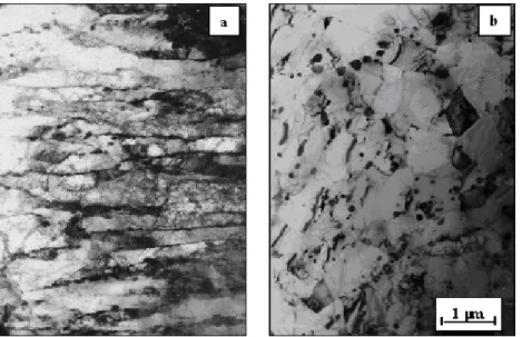
In the present study, TEM and SEM investigations were carried out to determine the characteristics of the tempered microstructures. On the TEM micrograph (see figure A.II.9a in the following), one can see lath martensite with M23C6
carbides at boundaries and formation of polygon dislocations substructures of only few microns in size within lath martensite.
It was evidenced in the present study that light optical observations after etching do not allow to evidence the recovery of the lath martensite microstructure as carbides remain aligned following the initial lath boundary. To do so, it is necessary to perform SEM investigations with the backscattered (BSE) channelling contrast after colloidal silica polishing
of the specimens. In this case, image contrasts corresponds to changes in crystallographic orientations. SEM-BSE micrographs are shown in figures A.I.7a and A.I.7b. Both the two micrographs evidence breaks in the laths and the beginning of their decomposition into fine equiaxed grains. The comparison between the P91 and the T91 steel also evidences a higher lath thickness in the T91 steel which can be related to the longer tempering time.
a b
2 µm
Figure A.I.7. Microstructures (a). Tempered P91 steel (SEM observation after colloidal silica polishing) (b). Tempered T91 steel (SEM observation after colloidal silica polishing)
3. Mechanical properties
3.1. Manufacturing reports
For the P91 steel, no information about mechanical properties of the steel was given. However, Prunier et al (1998) have reported a 0.2 proof stress of 325 MPa and 538 MPa respectively at 625°C and 22°C, and tensile strengths of 338 MPa and 688 MPa respectively at 625°C and 22°C. Unfortunately, Prunier et al (1998) did not give the testing conditions, especially the strain rate that is a very important factor as it will be shown later. For the T91 steel, both Charpy impact tests at – 20°C, 0°C and + 20°C and tensile tests at 20°C and 550°C were carried out. Tensile properties of the T91 steel are reported in table A.I.5. No differences in tensile properties in the rolling and transverse directions were evidenced at 20°C and 550°C.
Direction Test temperature 0.2 % proof stress Tensile strength Final elongation Reduction of area
Rolling direction 20°C 466 MPa 639 MPa 25.0 % 74.2 %
Rolling direction 550°C 323 MPa 378 MPa 21.0 % 84.8 %
Transverse direction 20°C 458 MPa 634 MPa 27.0 % 75.1 %
Transverse direction 550°C 331 MPa 374 MPa 21.0 % 84.8 %
Table A.I.5. Tensile properties of the T91 steel reported in the fabrication report (Welding Framatome (2003))
The values of KCV at 20°C ranged from 25.8 to 27.8 daJcm-2 whereas the specification for acceptance is 9.0 daJcm-2
(minimum accepted value).
3.2. Tensile strength and 0.2% proof stress calculations
In Bestwick and Escaravage (1998), equations of evolution of the 0.2% proof stress, in the following, and the tensile
strength, in the following, with respect to the temperature have been determined for 9Cr1Mo-NbV steels as:
2 . 0 p R m R 3 6 2 3 2 . 0 p 494.636 0.45486T 1.3264.10 T 1.9024.10 T R = − + − − − (T en °C) (eq. A.I.12) 4 9 3 6 2 3 m 677.95 1.4279T 6.6248.10 T 13.187.10 T 7.4131.10 T R = − + − − − + − (T en °C) (eq. A.I.13)
( = 260 MPa at 625°C, 326 MPa at 550°C and 383 MPa at 450°C and = 285 MPa at 625°C, 381 MPa at 550°C and 479
MPa at 450°C). Note that equations A.I.12 and A.I.13 were established from results of tensile tests probably carried out at a strain rate of 10 2 . 0 p R Rm
-5 s-1 and at two temperatures: the room temperature i.e. 20°C and 550°C so that their validity is
Warreing (1994) has established the following formulas for the Young’s modulus: ) C 650 T C 500 ( T . 240 295000 ) T ( E and ) C 500 T C 20 ( T . 58 . 64 207300 ) T ( E = − ° < < ° = − ° < < ° (eq. A.I.14)
(E = 150,000 MPa at 625°C, 163,000 MPa at 550°C and 178,000 MPa at 450°C).
Some authors like Pickering (1997), have suggested that the 0.2% proof stress can be described by an Hall-Petch type relationship with adding the strengthening contribution of carbides precipitates:
P 2 / 1 2 . 0 =A+Bd +σ σ − (eq. A.I.15) b 2 D ln C P= λ σ (eq. A.I.16)
where λ = interparticle spacing, D = particle diameter and b = burgers vector of slip dislocations and C is a constant .
3.3. Experiments and results
The experimental facility used to carry out the tensile tests of the present study is described in appendix B.D. Tensile tests were performed on smooth cylindrical bars having a maximum gauge length of 19 mm and a gauge diameter of 3 mm (see figure A.I.8) at 450 and 550°C on the T91 steel and 625°C on the P91 steel in the strain rate domain from 10-5 to
10-2 s-1.The elongation of the specimen was determined, using a linear variable transducer with a sensitivity of 1 µm, as:
0 g g L L ∆ = ε (eq. A.I.17)
where ∆Lg is the elongation of the gauge length and Lg0 is the initial gauge length equal to 10 mm.
19 mm
Lg0 = 10 mm
Figure A.I.8. Geometry of the smooth round tensile specimens
Tensile tests were both carried out using specimens manufacturing in the transverse (T) and longitudinal (L) directions of the pipe for the P91 steel and the sheet for the T91 steel. Results show no difference between both loading direction so that the two materials exhibit isotropy in mechanical properties. A similar study was carried out by Sasaki et al (1991) on a pipe of the same origin than the P91 steel with the conclusion that the tensile properties were very similar along L and T directions. a b E ngineer ing str es s (MP a) E ngineer ing str es s (MP a) Elongation (%) Elongation (%) 450°C 550°C 625°C 5 10 15 20 5 10 15 20 0 100 100 0 200 300 400 200 300 400 500 0 0 5 .10-2 s-1 10-2 s-1 10-3 s-1 10-4 s-1 10-5 s-1 a b
Figure A.I.9. Tensile tests on P91 steel - (a) at 625°C and strain rates of 5.10-2, 10-2, 10-3, 10-4 and 10-5 s-1 (b) at 1.10-3 s-1 and
temperatures of 450°C, 550°C and 625°C
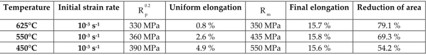
Young’s modulus were found to be in accordance with those given by equation A.I.14. 0.2% proof stress, tensile strength, uniform elongation and reduction of area are given in table A.I.6 where the uniform elongation is the value of
elongation when the value of the tensile strength, , is reached. More experimental results are given in appendix A
table A.A.1. The results are also in agreement with these of Sasaki et al (1991). It can be noticed in table A.I.6 that the material ductility, represented by the reduction of the specimen area, does not depend on the tensile strain rate at 625°C.
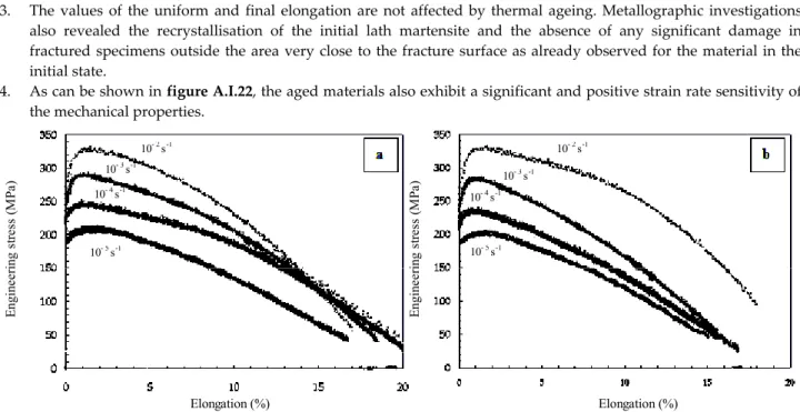
m R