Science Arts & Métiers (SAM)
is an open access repository that collects the work of Arts et Métiers Institute of
Technology researchers and makes it freely available over the web where possible.
This is an author-deposited version published in: https://sam.ensam.eu
Handle ID: .http://hdl.handle.net/10985/6377
To cite this version :
Hristiyan KANCHEV, Di LU, Frédéric COLAS, Vladimir LAZAROV, Bruno FRANCOIS - Energy management and operational planning of a microgrid with a PV-based active generator for Smart Grid Applications - 2011
Abstract— The development of energy management tools for consumers and next generation PV installations, including storage units, provides flexibility to distribution system operators. In this paper the aggregation and implementation of this new energy management method for business customers in a microgrid power system is presented. The proposed energy management system is organized according to different functions and is implemented in two parts: a central energy management of
the microgrid and a local power management at the
customer side.The central and local management systems exchange data and orders through a communication network. The power planning is designed according to the prediction for PV power production and the load forecasting
by taking into account the capabilities of dispatched customers. According to received grid power references, additional functions are also designed to manage locally the power flows between the various sources. Application to the case of a hybrid supercapacitor battery based PV active generator is presented.
Index Terms—Smart grids, sustainable energy, power planning, energy management, micro grid, renewable energy prediction, load forecasting
I. INTRODUCTION
he need to reduce pollutant gas emissions and the liberalization of the electricity market have led to a large scale development of distributed renewable energy
generators in electrical grids [1]. Nowadays renewable
energy generators, such as photovoltaic or wind power
generators, are used to reduce fuel consumption and
greenhouse gas emissions. However, the output power fluctuation of renewable energies may cause excess variations of the grid’s voltage and frequency. In recent
years, storage systems have been used to design active
generators, which are able to provide an energy reserve with a less fluctuating output power [2-4]. As example, fig. 1 shows a home application with PV panels and a
demand response capability via some controllable loads and storage units. During the day this home application may be a power producer or a consumer – also known as a “prosumer”.
A few years ago, Energy boxes (E-boxes) were
developed in order to follow energy consumption [5].
Fig.1. Prosumer with load demand response and production capabilities.
They have been upgraded to increase consumer satisfaction with the option for automatic control of some
loads. Customer-enabled management provides
opportunities for consumption adaptation to time pricing
and new grid services for higher quality power supply (Yellow Strom’s meter, Linky meter, …). In this paper we consider advanced E-boxes with on-board intelligence, which receive signals from the grid operator and are able to reduce home demand or increase power production as in
the NEDO project of Ohta City [6].
Considerable research activity is focused on the integration of large amounts of Distributed Energy Resources (DER) in the electrical system. The attention is now oriented toward the use of DER for improving grid operation by contributing to ancillary services, increasing
the energy reserve and reducing CO2 emissions. In
practice, new facilities are expected to reduce congestion, to minimize the production costs and to maintain the frequency and voltage. These developments require a fundamental redesign of the grid control. Here an aggregated architecture of an urban power system is
considered as means to facilitate the integration of
distributed prosumers both in the electrical system and in the market.
In this study home applications are coordinated with conventional production units by a central Energy Management System (EMS) to form a microgrid (fig. 2).
The global objective consists in matching the total power
production to demand in an optimal way [7,8]. This concept is pertinent in the framework of smart grids through the combined use of an additional communication network within an intelligent energy management system and local controllers [9,10]. This scheme is a step between current grid requirements and future needs.
Energy management and power planning of a
microgrid with a PV-based active generator for
Smart Grid Applications
This paper tackles the problem of the optimal planning of smart grids in the presence of prosumers. A coordinated management of energy resources is proposed through a
communication network. An E-box exchanges data with the central EMS and receives references. In section II, the
paper recalls the organization of the embedded local energy management of a prosumer. Section III is focused on the general scheme of the microgrid EMS. Finally, our planning and long-term energy management is detailed in the fourth section.Section V describes the local controller in charge of the coordination of home energy resources
whose function is to satisfy grid power references.
Experimental results are presented in the last section.
Loads
Urban power network Local Controller Active generator Gas Turbine Power Prediction Load forecasting Power points setting Power/energy Availability Electricity Market Techno-economic optimization of power/energy management Microgrid Central Energy Management System
E nviron nem en tal Im pa ct P rosu m er Local Controller Communication Bus MCEMS Loads Communication Bus
…
Distributed System Operator
…
…
Controllable loads Local Controller
Fig.2. Framework of the central energy management system.
II. LOCAL ENERGY MANAGEMENT
To facilitate the presentation of theoretical developments a single prosumer and a micro gas turbine
are considered in this microgrid (fig. 3). The E-box
integrates three functions: a load manager, an advanced meter and a local energy management.
The load manager enables customers to automatically pre-program appliances to turn on when prices are lower or to create energy consumption habits, such as:
uninterrupted supply of critical loads, time programmable use, etc. Moreover it can reduce a part of the home power demand when the grid is under stress by disconnecting offered controllable loads [11]. An advanced meter feeds the local energy management system as well as the load manager. Moreover the utility is able to ping the meter.
Photovoltaic panels are associated with a storage system, which includes a set of batteries as a long-term storage device [12, 13] and a set of ultracapacitors as a fast dynamic power regulator [14, 15] (fig. 1). These are coupled via a DC bus by choppers and are connected to the
microgrid by a three-phase inverter [16]. The interesting aspect of this hybrid generator is that it is able to deliver a prescribed power level (Pag_ref) like a conventional generator (for example, a gas micro turbine). The local energy management thus allows the use of PV energy according to the grid operator requirement also at times
when the sun is not shining. In this case batteries are
tapped to provide the required power. To highlight the
difference to conventional PV panels, this concept is called an active generator. Excess PV energy is stored in batteries for use when needed and the local real time power control is performed with ultracapacitors.
The E-box gives a remote control of facility to the grid operators to allow faster adjustments to conditions and to give more flexibility to re-route power in a certain offered margin.
Micro Grid
Central energy management
Micro Gas Turbine Controlable Loads Critical Loads Ultracapacitors Inverter
Local energy management
DC bus PV Batteries Loads Prosumer Pmt_ref Pag_ref Ebat tt Load manager Advanced meter Controllable loads E. B o x
Fig.3. Microgrid integration of a prosumer and a micro gas turbine.
III. MICROGRID ENERGY MANAGEMENT
From a general point of view the task of the central
EMS is to manage the power and the energy between sources and loads into the microgrid. The real and reactive power production must then be shared among the Distributed Energy Resource (DER) units (here a single prosumer) and the gas microturbine. So the central energy management system must assign real and reactive power references and also other appropriate control signals to the DER units, conventional production units and controllable loads. Microgrid management is analyzed through various functions that are classified in a timing scale (fig. 4).
Long-term energy management includes:
- the hourly “RES production forecast” including the time dependency of the prime source, environmental impacts and cost of generation,
- the management of controllable loads that may be disconnected/shed according to the supervision requirement,
- the provision of an appropriate level of power reserve capacity according to the electricity market and the load
demand forecast,
- the maintenance intervals.
Short-term power balancing includes:
- the RMS voltage regulation and primary frequency control,
- the real time power dispatching among internal sources of a DER (PV generator, batteries, ultracapacitors for our exemple in fig. 1).
According to the different management objectives, the proposed energy supervision system is implemented in two locations: a central EMS of the whole micro grid for the long-term energy management, and a local energy management system in the E-box for the short-term power balancing.
A communication between these two management units
is set up because the data acquisition and information
about the states of each resource (such as the energy capacity and the real-time produced power) are very important for the central EMS of the microgrid. The control orders from the microgrid central energy management are also sent to the local supervisor (fig. 2).
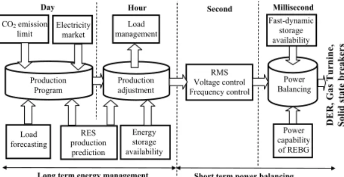
In order to integrate active generators into the electrical system, the central energy management has to be upgraded. Several functions in the central EMS have to be modified or created as power prediction of the renewable energy, load forecasting, energy storage reserve, peak shaving, maximized use of renewable energy source, reduction of CO2 emissions and new power planning (fig. 4). In the next section a long-term energy management is proposed. Power capability of REBG Fast-dynamic storage availability Electricity market Load management RMS Voltage control Frequency control Millisecond Second Hour RES production prediction Day Load forecasting Production Program Production adjustment Power Balancing
Short term power balancing Long term energy management
Energy storage availability D E R, Gas Tu rnin e, So li d state b rea k er s CO2 emission limit
Fig.4. Timing classification of control functions for EMS.
IV. LONG-TERM ENERGY MANAGEMENT
A. PV power prediction and load forecasting
In the case study, the naturally poor predictability of the
level of solar energy is a weakness for the purpose of its
use in an electric system. Photovoltaic panels provide electrical power only during the day with a power peak around the midday. Meanwhile huge production variations may occur.
According to the weather forecasting and the historic
database of PV power, a 24-hour-ahead approximated PV
power prediction profile (PPV_24h
~ ) can be obtained each half an hour (fig. 5). The load forecasting is also very important for the energy management.
Based on historic electrical power production demands, the behavior of the loads can be forecast and estimated. Several factors influence the load in the electrical network: the weather situation (temperature, cloud coverage, etc.), economic activity (huge modifications of load forecasting
are necessary during the holiday periods), standard
working hours, etc.
Fig. 5. 24-hour-ahead PV power prediction ( h PV P _24
~ ).
“Classic” methods of load forecasting are based on meteorological information and historic consumption data [17]. A 24-hour-ahead load forecasting profile (P~Load_24h) is given in fig. 6 with data recorded each half hour.
We have set out the pattern of daily home power consumption in time-related categories: the morning peak (fig.6, zone A), the lunch peak (fig.6, zone B), the sag in the afternoon (fig.6, zone C), the evening peak (fig.6, zone D) and the night sag (fig.6, zone E).
B. Energy estimation
For the energy estimation, the initial time point is considered as the start of the day (t0) and the day’s duration is named (∆t) (fig. 7). Both parameters depend on the season and the weather conditions.
The scheduled energy of the PV production during each 1/2h interval can be calculated with data from the PV power prediction as: ( ) ) . ( ~ . ) ( ~ ~ 0 24 _ 1 24 _ 2 / 1 _ 0 0 Te n t P Te dt t P E t n Te PV h nTe t PV h h PV =
∫
= + + + + (1)with Te=30min and n∈
{
0,1,...,47}
.In order to plan the production program, the energy, which is demanded by the load is also estimated during the same interval: ( ) ) . ( ~ . ) ( ~ ~ 0 24 _ 1 24 _ 2 / 1 _ 0 0 Te n t P Te dt t P E t n Te Load h nTe t Load h h Load =
∫
= + + + + (2)The rated power of the micro gas turbine (
P
MGT_max) is33kW. In order to minimize energy losses and air pollution at each start of the gas turbine, the gas turbine should always work.Therefore, in the case of low power demand, the turbine is forced to work with a low power level ( PMGT_min ); corresponding to the minimum energy:
min _ 0 _min min _ 2 / 1 _ . ~ MGT Te MGT h MGT P dt Te P E =
∫
= (3)Because of the rated power of the batteries (Pbat_max), the
exchanged energy during 1/2h with the batteries is limited as:
max _ 0 _max max _ 2 / 1 _ . ~ bat Te bat h bat P dt Te P E =
∫
= (4) t0 t0+∆t t0+24h t day nightFig. 7 Time axis for the PV power application
C. Setting of half-hour power references
In this studied case two power sources are considered: a PV based active generator (at the prosumer home) and a micro gas turbine. Because of the renewable energy benefits (less gas emission and low operating cost), the PV based active generator is considered the prior source, and the micro gas turbine a back-up source for the missing energy. The objective is to set one charging/discharging cycle for batteries every day. The depth of discharge is maintained between 0% and 70%
during normal operation to increase the battery lifetime. Here the storage battery capacity is 10 kWh. Moreover the rated
battery power (Pbat_max) is also considered.
According to daily predictions of the available power and energy from the PV (P~PV_24h,E~PV_1/2h ) and the required power
and energy of the loads ( PLoad_24h ELoad_1/2h
~ ,
~ ), a power production planning for the prosumer (PAG_ref0) and for the micro turbine (PMGT_ref0) must be determined. The central energy management system refreshes the power references each 30 minutes. As no power is available from PV panels during the night, power references are calculated separately for the night and for the day.
In the day (t0<t<t0+∆t), and for each 1/2h period, two cases are considered.
Case 1: If the available PV energy added with the minimum
gas turbine energy is less than the demanded load energy (E~PV_1/2h+E~MGT_1/2h_min<E~load_1/2h), the PV panels can work
with a Maximum Power Point Tracking (MPPT) algorithm and all PV power is injected in the grid. The micro gas turbine has to generate the missing power:
h _ PV ref _ AG P ~ P 0= 24 , (5) 0 24 0 Load_ h AG_ref ref _ MGT P P ~ P = − . (6)
Case 2: Otherwise, the available PV energy added to the
minimum gas turbine energy is more than the demanded load energy. Priority is then given to the renewable energy for the electrical production so that the micro gas turbine works with minimum power and the active generator power is limited to the missing power:
min _ MGT h _ Load ref _ AG P P ~ P 0= 24 − , (7) min _ MGT ref _ MGT P P 0 = . (8)
The excess PV energy will be managed by the local controller (paragraph V).
The energy management during the night (t0+∆t<t<t0+24h) depends on the available energy from batteries in homes. This energy can be estimated or communicated by the E-box to the central EMS. In the night two cases are also distinguished. For both cases batteries have to be discharged in order to be ready for charging the next day at t0. According to the stored energy (E~bat(t0+nTe)) and the rated energy (E~bat_1/2h_max), the available energy of batteries during the next 1/2h is obtained:
[
E~ ,E~ (t nTe)]
min ) t (
E~bat_1/2h_rest = bat_1/2h_max bat 0+ (9)
Case 1: If the available stored battery energy, added to the
minimum gas turbine energy is more than the demanded energy from loads (E~bat_1/2h_rest+E~MGT_1/2_min>E~load_1/2h), priority is given to the active generator for the electrical production since it has enough previously stored energy from PV panels. The gas turbine will work with minimum power:
min _ MGT h _ Load ref _ AG P P ~ P 0= 24 − , (10) min _ MGT ref _ MGT P P 0 = . (11)
Case 2: Otherwise, the stored battery energy added with the minimum gas turbine energy is less than the demanded energy from the loads. Then the power reference of the active generator is calculated in order to discharge batteries and the gas turbine must generate the missing power:
Te E P bat h rest ref AG _ 2 / 1 _ 0 _ ~ = , (12) 0 _ 24 _ 0 _ ~ ref AG h Load ref MGT P P P = − . (13)
D. Implementation and obtained results
In order to illustrate the theoretical results, the power planning (24h-ahead) of the load forecasting (fig. 6) is considered, as well as the estimated PV power (fig. 5) with
t
0 =7h00 and∆
t
=12h30. Estimations of the required energy for the loads (E~Load_day) and the available energy fromthe PV panels (EPV_day
~ ) during the day (
t t t
t0< < 0+∆ ) show that too much renewable energy is available (fig. 8).
As the gas microturbine must produce the minimum energy during the day, the surplus energy is estimated as:
max _ min _ _ _ _ ~ ~ ~ ~ bat day MGT day Load day PV E E E E E= − + < ∆ . (14)
∫
+ = t h t MGT day MGT P dt E _ _min 24 _min 0 0 ~ (15) This energy can be stored in batteries. The required energy from the gas microturbine for night operation is then deduced (fig. 9): night bat night Load night MGT E E E~ _ = ~ _ −~ _ . (16)With E~bat_night =∆E~.
day _ MGT E~ day _ PV E~ day _ Load E~ Ebat_day ~ min _ day _ MGT E~ max _ bat E ini _ bat E E~ ∆
Fig. 8. Energy analysis for the day.
night _ Load E~ max _ bat E night _ bat E~ EMGT_night ~ Fig. 9. Energy analysis for the night.
As a communication network exists, it is easy to replace the estimated value of the battery energy with a sensed value, which is sent by the E-box at the beginning of the night (t0+∆t). Between 7h00 and 9h00, the PV power is not enough (fig. 5); the power reference is well calculated for the gas microturbine (fig. 10).
After 9h00 the turbine power reference is set to the minimum value until 17h00. At 19h30, the power reference for the prosumer is adapted to discharge batteries; the peak value of the turbine power reference is reduced (fig. 10). Fig. 11 shows the sensed value of the PV power and the theoretical one, which can be generated with a MPPT algorithm. Between 11h00 and 12h30 the available PV power exceeds the requested power from loads. Fig. 11 shows that all the PV power is not delivered to the grid. The local energy management system has stored or
limited part of the available PV power; the implementation is detailed in the next section.
Fig. 12 shows that the real sensed value of the total load power may be significantly different from the 24h-ahead estimated one. The task of the primary control is to eliminate
these errors. This primary control is included inside each local energy management of generators.
7h00 9h00 11h00 13h00 15h00 17h00 19h00 21h00 23h00 1h00+1day 3h00 5h00 7h00 -4 -3 -2 -1 0 1 2 3 -4 Time Po we r( kW ) PLoad24h PAGref PMGTref
Fig. 10. Power references from the power planning in the central energy management. 7h000 9h00 11h00 13h00 15h00 17h00 19h00 21h00 23h00 1h00+1day 3h00 5h00 7h00 0.5 1 1.5 2 2.5 3 Time P o w e r(k W ) PPV PPVMPPT
Fig. 11. The measured PV power and the estimated PV power.
7h000 9h00 11h00 13h00 15h00 17h00 19h00 21h00 23h00 1h00+1day 3h00 5h00 7h00 0.5 1 1.5 2 2.5 3 3.5 4 4.5 Time Po we r( kW ) PLoad PLoad
V. LOCAL CONTROLLER OF THE PV ACTIVE GENERATOR
A. Local energy management
The central EMS sends a requested power reference
0
ref _ AG
P to the active generator each half of an hour. The local controller has to distribute this power reference inside the PV active generator.
In the active generator of the prosumer, two different types of energy storage technologies are coupled with the PV generator. Lead acid batteries are chosen because of their low cost and
their wide availability. They can be used as long-term energy storage in case of PV overproduction. In the case of PV energy shortage, they will be used to provide power. However PV panels are not an ideal source for battery charging as the output is unreliable and is dependent on weather conditions. It can cause deep discharging, undercharging and overcharging of batteries. They may damage batteries and shorten their lifetime [18, 19]. Therefore, in order to optimize battery use, a single charging/discharging cycle is set during the day. Moreover, during every half of an hour, the battery charging power reference (Pbat_ref0) is constant.
The charging of batteries is decided if the available PV power in MPPT (P~PV_24h) is higher than the requested power reference (PAG_ref0) and if batteries are not full (fig. 13). The
State Of Charge (S~OC) has to be estimated [20, 21] and
compared with the maximum value ( max
~
OC
S ).
The night case is simpler as the PV power is null. The batteries are considered as the main source until that the minimum value of the batteries S~OC is achieved.
For security reasons the obtained battery power reference is limited to the rated power value (Pbat_max).
h PV ref AG P P _ 0 _24 ~ ≤ max ~OC SOC S ≤ 0 0= ref _ bat
P bat_ref0 PPV_24h PAG_ref0 ~
P = −
Start
Fig.13. Flow diagram of the battery charging for the battery management.
B. Primary frequency regulation
The central energy management system sends a wished power referencePAG_ ref0 to the active generator each half of an hour. This quantity is the planned exchanged power of the active generator in a long time range. As uncertainties exist in the load forecasting but also in the PV power prediction, a primary frequency control must be used to adjust the power production of generators in real time in order to achieve the real-time power balancing. A primary frequency control has been implemented onto the active generator in order to ensure the short-term power balancing (fig. 3).
The grid frequency control is a conventional solution to the
real-time power balancing [22, 23]. When the frequency deviation exceeds a pre-defined threshold value, the controller
is activated to increase or decrease the power for restoring the power balance. The primary frequency control contribution of the generator is based on a droop constant, which gives the additional power that is supplied as a function of the frequency deviation [24-26] (fig. 14):
( )
t k f( )
t k(
f f( )
t)
PAG ref ) − − = ∆ − = ∆ _ 0 . (17) 0f the frequency in the normal operation (50 Hz for our case study), f) is the sensed value of the frequency. The power/frequency constant is calculated as:
0 _ 1 f P s k= AG rated
with the droop: s 5= %and PAG_rated is the maximum available
power, which can be exported to the microgrid.
k + + + _ ∆f fo f ) pAG_ref(t) PAG_ref0 ∆PAG_ref(t)
Fig.14. Droop controller for primary frequency control.
C. Real-time power balancing inside the active generator
The active generator has to provide the real time power reference (pAG _ref
( )
t ), which is the sum of the secondary power reference ( PAG_ref0 ) with the primary power reference (( )
tPAG _ref
∆ ).
In the active generator of the prosumer, batteries are used to provide guaranteed energy to the microgrid operator. The
real-time power balancing must be implemented by a power buffer with fast dynamic capabilities. Ultracapacitors are fast dynamic storage systems with high power exchange capabilities. They are suitable for the optimal charging of the battery and for supplying peak power to the grid if necessary, but their energy density is low.
The real time power balancing depends on the availability of the ultracapacitors. They can be checked if the sensed value of the ultracapacitor voltage (u)uc) is in the security domain, i.e. between a minimum value (uuc_min) and a maximum value (uuc_max ). In this “Storage mode”, ultracapacitors can be used to increase or decrease the exchanged power with the grid in order to represent a faithful real-time power reference (pAG_ref(t)).
If ultracapacitors are over-loaded (u)uc >uuc_max ), excess PV power can not be stored in them so the produced PV power must be limited to satisfy the real time power reference. This mode is called “PV Limitation Mode”.
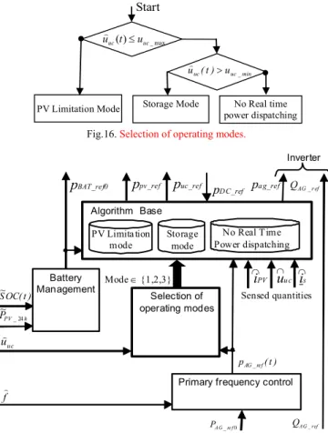
If the PV power is insufficient and ultracapacitors are discharged it is not possible to supply the real time power reference. This mode is called “No real time power dispatching mode”. Thus, one algorithm (corresponding to one operating mode) is executed and calculates power references for each source according to the selected operating mode and the measured quantities (fig. 16). These power references are then
transformed to current or voltage references for closed loop controls [27]. max _ ) ( uc uct u u) ≤ Start min _ uc uc(t) u u) >
PV Limitation Mode Storage Mode No Real time power dispatching
Fig.16. Selection of operating modes.
Sensed quantities is ∩ uu c ∩ ∩ iPV Algorithm Base ppv_ref pBAT_ref0 puc_ref p DC_ref PV Limitation mode pa g_ref Mode ∈ {1,2,3} uc u) ) t ( pAG_ref ref A G Q _ Selection of operating modes Battery Management ) t ( OC S~ No Real Time Power dispatching Storage mode
Primary frequency control
0 _ re f A G P h PV P~ _24 Inverter r ef AG Q _ f )
Fig. 17. Organization of the power control of the local controller.
D. Real-time power dispatching
The real-time power dispatching among the batteries, the ultracapacitors and the PV generator must be set in order to deduce the prescribed power references.
• Mode N°1 (Storage mode)
For this mode the produced electric power from PV panels may be higher or lower than the power reference (pAG_ref(t)). Moreover, ultracapacitors are available and can
be used to compensate for this difference. So the active generator can deliver the electric power to meet grid power references.
During the day, the photovoltaic panels are working in MPPT with a particular algorithm (
f
MPPT), which requires the sensed value of the PV currenti
)
pv:)
(
_ref MPPT pv
pv
f
i
p
=
)
. (18)For the theoretical analysis, batteries and ultracapacitors are assumed to be in generating mode. The power flow from the
sources to the grid is described in the Fig. 18. The total exchanged power with both storage units is called
p
sto. The exchanged power with the capacitor of the DC bus is calledp . In figDC .18 this power is composed of a positive part ( pDC_load to increase the DC voltage if necessary) and anegative part ( pDC_disload to decrease the DC voltage if
necessary). Modelling equations of the power flow are summarized in table I.
If the resistor of the grid filter ( R ) is known, losses can be estimated with the sensed grid currents (i) ): s
2 3 ~ s filter R i L = ⋅ ⋅) (19)
They are used to calculate the total AC power reference (pAC_ref), which must be supplied by the grid power electronic inverter (control equation R4c in table 1) [28]. Part of this power is required to regulate the DC bus (pDC_ref).
This power reference is taken into account in the power flow management (R3c in table 1). The reference of the exchanged power with both storage units is calculated by using an estimation of the produced PV power (R2c). Then the power
reference for ultracapacitors is obtained by taking into account the value sensed of the batteries’ power (
p)
bat) in the control equation (R1c). pp v pb a t pu c Lfilte r pa g S o u r ce s C o n n ec t io n t o g r i d B u s D C pA C psto pc o n v lo a d D C p _ d i s l o a d D C p _Fig. 18. Power flow in the storage mode. TABLE I.
MODELING AND CONTROL EQUATIONS OF THE POWER
Modeling equations Power management
uc bat
sto p p
p = + (R1) puc_ref =psto_re f−p)bat (R1c) sto
pv
conv p p
p = + (R2) psto_ref =pconv_ref −p~pv (R2c)
DC conv
AC p p
p = − (R3) pconv_ref =pAC_ref +pD C_ref (R3c) filter
AC
ag p L
p = − (R4) AC_ref ag_ref Lfilter
~ p
p = + (R4c)
• Mode N°2 (Limitation mode)
In this mode ultracapacitiors cannot be used to manage the real time power dispatching because they are fully charged. If the available power from the PV panels (in MPPT, P~PV_MPPT) is more than the required power reference, it is not possible to send all PV power into storage units. Hence, ultracapacitors have to be setup in a stand by mode:
0 = ) t ( puc_ref (20)
The produced power from the PV panels must be limited to the power reference set point:
) t ( p ) t ( p ) t (
ppv_ref = conv_ref − bat_ref (21)
The PV converter controller can reduce the PV power production by regulating the voltage across the PV panels (u ). PV
Mode N°3 (No real time power dispatching mode)
In this mode, ultracapacitors are disloaded and so cannot be discharged anymore. They cannot be used to give more power if the PV power is not enough for the power supply. Hence ultracapacitors have to be setup in stand by:
0 = ) t ( puc_ref (22)
And the PV panels must work in MPPT.
VI. EXPERIMENTAL RESULTS OF A CASE STUDY
In order to test our energy management, a prototype of the studied active generator has been built. A set of 10kWh batteries and two 112kW (peak power) ultracapacitor modules are used as storage components. The control system is implemented into a DSpace card (fig.18). Experimental results are presented when the hybrid generator is operated in the storage mode and uses ultracapacitors.
In night mode, there is no electrical production from PV power. Fig. 19 shows the variation of the grid power and the powers from both storage units when a step change of the grid power reference (PAG_ref0) from 0 to 200W occurs. The batteries
are ordered to be discharged. However, their power increases slowly and can not instantaneously satisfy a sudden power
change. Experimental results show that the ultracapacitors are are discharged with a high power in order to meet this power reference.
The second experimental test presented corresponds to
daytime operation. A constant 200W power reference (PAG_ref0)
is received. The batteries are charged with a power of 100W. In presented experimental results the PV power production varies from 300W to 450W (fig. 20). When the PV production
increases quickly, the ultracapacitors help to perform the power balancing while charging more power with a higher current. The sensed batteries’ power remains constant and variations of the generated grid power are smaller.
Fig.18. Prototype hybrid system for the experimental test.
pAG_mes(Ch1): 100W/div; pbat_mes(Ch2): 50W/div ;
puc_mes(Ch3): 50W/div; udc_mes(Ch4): 150V/div.
Fig.19. Experimental results in the night mode.
pAG_mes(Ch1): 100W/div; pbat_mes(Ch2): 100W/div ;
puc_mes(Ch3): 150W/div; pPV_mes (Ch4): 150W/div.
Fig.20. Experimental results in the day mode.
VII. CONCLUSION
In this paper a microgrid organization is studied in order to define the roles and the required control systems for massive dispersed PV generators’ integration in the electrical system. The main problem is that the output power from most renewable energy based generators fluctuates depending on
weather conditions when the power quality of the grid may decrease. A solution is proposed to promote and coordinate more efficiently conventional and PV-based generators in the plan to lower energy costs for customers, to achieve energy independence and to reduce greenhouse gas emissions. This work falls into the framework of Smart Grids since the solution relies on an enhanced energy management system and a communication network.
Power planning has been proposed to perform the day-ahead power scheduling for the conventional and PV generators. The presented scheme relies on PV power predictions and load forecasting. The scheme also sets out plans for the use of the distributed battery storage. Power references are communicated to customers. An open local controller inside an energy box has been developed and presented in order to satisfy grid operator requirements according the local state of the sources (state of
the batteries’ charge, solar radiation, etc). At the customer side, two storage technologies are used to enable grid demand
management and renewable energy integration. Batteries are used to ensure an energy reserve for the grid operator.
Supercapacitors are used to balance fast power variations coming from the PV generator and from the primary frequency control. A strategy has been presented to drive them according to the solar energy resources and grid requirements. Experimental results of the proposed smart grid solution for planning and operating the microgrid are presented. Currently, further research is aimed at hypothetical business cases associated with smart grids and distributed resource integration to provide more value to the microgrid management.
VIII. ACKNOWLEDGMENT
This work is supported by the French National Agency for Research (ANR SuperEner Project) and the AUF.
REFERENCES
[1] M. Liserrre, T. Sauter, J. Y. Hung, “Future Energy Systems, integrating renewable energy sources into the smart power grid through industrial electronics”, IEEE Industrial Electronics magazine, pp18-37, vol. 4, no1, march 2010.
[2] T. Zhou, B. François, “Modelling and control design of hydrogen production process for an active wind hybrid power system”, International Journal of Hydrogen Energy, Elsevier, vol.34, 2009, pp 21-30.
[3] I. Hadipaschalis, A. Poullikkas, V. Efthimiou, “Overview of current and future energy storage technologies for electric power applications”, Renewable and sustainable energy reviews, 13, 2009, pp 1513-1522. [4] M.E. Glavin, P.K.W. Chan, S. Armstrong, W.G. Hurley, “A stand-alone
photovoltaic supercapacitor battery hybrid energy storage system”, 13 th
Power electronics and motion control conference, 2008, CDROM. [5] J. Hirsch, “Performance of open-standard PLV technologies on ERDF
distribution network”, Metering’09, 9-10 June 2009, London, UK [6] R. Hara, H. Kita, T. Tanabe, H. Sugihara, A. Kuwayam, S. Miwa,
“Testing the technologies – Demonstration Grid-Connected Photovoltaic projects in Japan“, IEEE PES Power & Energy Magazine, May-June 2009, p. 77-85.
[7] N. Hatziargyriou, H. Asano, R. Iravani, C. Marnay, “Microgrids”,IEEE Power&Energy magazine, pp78-94, july/august 2007.
[8] B. Kroposki, R.Lasseter, T. Ise, S. Morozumi, S. Papathanasiou, N. Hatziargyriou, “Making microgrids work”, IEEE Power&Energy magazine, May-June 2008.
[9] D. Lu, B. Francois, “Strategic framework of an energy management of a microgrid with photovoltaic-based active generator”, Electromotion 2009 EPE chapter, Lille, 1-3 July 2009, CD-ROM.
[10] M. Mcranaghan, A. Chuang, “Functions of a Local Controller to Coordinate Distributed Resources in a Smart Grid“, IEEE PES General Meeting, 20-24 July 2008, CD-ROM.
[11] X. Vallvé, A. Graillot, S. Gual, H. Colin, “Micro storage and demand side management in distributed PV grid-connected installations”, 9th
international conference, Electrical power quality and utilization, Barcelona, 9-11 October 2007, CD-ROM.
[12] S.J. Chiang, K.T. Chang, C.Y. Yen: Residential photovoltaic energy storage system, IEEE Transactions on Industrial Electronics, vol. 45, iss. 3, pp385 – 394, June 1998.
[13] G. Delille, B. Francois, “A review of some technical and economic features of energy storage technologies for distribution systems integration“, Ecological Engineering and Environment Protection, No1, p. 40-49, ISSN 1311-8668, 2009.
[14] C. Abbey and G. Joos, “Supercapacitor Energy Storage for Wind Energy Applications“, IEEE Transactions on Industrial Electronics vol.43, iss.3, pp.769-776, May 2007.
[15] F. Baalbergen, P. Bauer, J.A. Ferreira, “Energy Storage and Power Management for Typical 4Q-Load“, IEEE Transactions on Industrial Electronics, vol.56, iss.5, pp. 1485 - 1498, May 2009.
[16] E. Figueres, G. Garcera, J. Sandia, F-G Espin, J. Rubio, “Sensitivity study of the dynamics of three-phase photovoltaic inverters with an LCL grid
filter”, IEEE Transactions on Industrial Electronics, vol.56, no.3, March 2009.
[17] RTE (Réseau de Transports d’Electricité) de France, “Consommation francaise d’éléctricité caracteristiques et methode de prevision”, web site http://www.rte-france.com/
[18] R. Kaiser, “Optimized battery-management system to improve storage lifetime in renewable energy systems”, Journal of Power Sources, Vol. 168, Iss. 1, 25 May 2007, pp58-65.
[19] M. Lafoz, L. Garcia-Tabarés, M. Blanco, “Energy management in solar photovoltaic plants based on ESS”, Power Electronics and Motion Control Conference, EPE-PEMC 2008. 13th, Poznan, 1-3 Sept. 2008,
CD-ROM.
[20] Y. Lee, W. Wang, T. Kuo, “Soft computing for battery state of charge (BSOC) estimation in battery string systems”, IEEE Transactions on Industrial Electronics, vol.55, no.1, January 2008
[21] R. Kaiser, “Optimized battery-management system to improve storage lifetime in renewable energy systems”, Journal of Power Sources, Vol. 168, Iss. 1, 25 May 2007, pp58-65.
[22] J. Morren, S. W. H. de Haan, J. A. Ferreira, “Contribution of DG units to primary frequency control”, European transactions on electrical power, 2006, 16, pp. 507-521
[23] V. Courtecuisse, B. Robyns, B. François, M. Petit, J. Deuse, “Variable speed wind generators participation in primary frequency control”,Wind engineering, vol. 32, no3, pp 299-318, 2008.
[24] J. Vasquez, J. Guererro, A.Luna, P. Rodriguez, R. Teodorescu, “Adaptive droop control applied to voltage source inverters operating in grid-connected and islanded mode”, IEEE Transactions on Industrial Electronics, vol.56, no.10, October 2009
[25] B. Awad, J.Wu, N. Jenkins, “Control of distributed generation”, Elektrotechnik & Informationstechnik, August 2008
[26] P. Li, P. Degobert, B. Robyns, B. François, "Participation in the frequency regulation control of a resilient microgrid for a distribution network", International Journal of Integrated Energy Systems, vol.1, no1, January-June 2009.
[27] D. Lu, T. Zhou, H. Fakham, B. Francois, “Design of a power management system for a PV station including various storage technologies“,13th International Power Electronics and Motion Control Conference, EPE-PEMC 2008, Poznan, 1-3 septembre 2008, 9-2008, CD-ROM. [28] D. Lu, T. Zhou, H. Fakham, B. Francois, "Application of Petri Nets for the
energy management of a photovoltaic based power station including storage units", Renewable energy, Elsevier, vol. 35, Iss. 6, pp. 1117-1124, 2010.