Type here the email address of the main author as a footnote.
Review of advanced modelling methods for lattice steel towers
S. LANGLOIS
1, S. PRUD’HOMME
2, F. LÉGERON
1, F. POURSHARGH
1 1Université de Sherbrooke
2
Hydro-Québec
Canada
SUMMARY
The analysis of transmission line steel lattice towers is usually performed with simplified linear numerical methods. However, the actual behaviour of bolted lattice towers is complex and may be affected by different factors such as rotational stiffness of connections, bolt slippage, eccentricities at the connection, initial deformations of the members, etc. For this reason, most utilities perform full-scale tests for the qualification of new design of steel lattice transmission towers. These tests are expensive and add delays in the planning of the construction of new transmission lines. Advanced numerical methods were developed over the years and they may effectively provide more insight into the force distribution scheme and loading condition of individual members found in the steel structure and hence, help to optimize the use of full-scale experimental tests. The objective of this paper is to review the main strategies that were identified in order to model accurately the behaviour of steel lattice towers. It reviews a number of documents that were published on this subject and presents recent advances made with research projects performed at Université de Sherbrooke. First, the choice of elements is reviewed and traditional methods using truss elements, beam elements, or a combination of truss and beam elements are discussed. The possibility to use shell and 3D elements is also evaluated. Second, the behaviour of bolted connection is studied and strategies for including the effect of slippage, rotational stiffness and eccentricities are discussed. Third, a review of research works using static and dynamic analyses is presented. Finally, a novel hybrid simulation method combining experimental tests with numerical modelling is explained. In summary, many options are available for improving modeling of the complex behaviour of steel lattice towers. One needs to select hypotheses carefully to make sure that the model is compatible with the problem studied and that its complexity is minimized. Future works needed include the simplification of model building methods, further development of hybrid testing techniques, and validation of modeling techniques with full-scale lattice tower tests.
KEYWORDS
Transmission line design, lattice structures, finite element analysis, steel joints modelling, hybrid simulations.
2016 CIGRE-IEC Colloquium
21, rue d’Artois, F-75008 PARIS May 9-11, 2016
1
INTRODUCTION
The analysis of transmission line steel lattice towers, most often composed of steel angle members, is usually performed with simplified linear numerical methods. The analysis method used by designers around the world was compared to experimental tests in benchmarks realised by CIGRE working groups in 1991 and 2009 [1-2]. These documents showed that the hypotheses used by engineers could influence the accuracy of the predicted forces in tower members, especially for diagonal or bracing members that are lightly loaded. It also showed that this type of linear modelling works fine for design purposes because the forces in heavily loaded members can be accurately predicted. However, the actual behaviour of bolted lattice towers is complex and may be affected by different factors such as rotational stiffness of connections, bolt slippage, eccentricities at the connection, initial deformations of the members, etc. These complexities may result in unforeseen failures at tower members or joints. For this reason, most utilities perform full-scale tests for the qualification of new design of steel lattice transmission towers. These tests are expensive and add delays in the planning of the construction of new transmission lines. On the other hand, advanced numerical methods were developed over the years and they may effectively provide more insight into the force distribution scheme and loading condition of individual members found in the steel structure and hence, help to optimize the use of full-scale experimental tests. The objective of this paper is to review the main strategies that were identified in order to model accurately the behaviour of steel lattice towers. It reviews a number of documents that were published on this subject and presents recent advances made with research projects performed at Université de Sherbrooke. Advanced modelling methods have evolved rapidly over the last decades. This paper explains how theses modelling techniques can now be used by designers to perform advanced studies on the behaviour of steel lattice towers under various static and dynamic loading. Advanced modelling techniques are particularly useful for engineers to analyse past failure events or to avoid unexpected failures at full-scale qualifications tests. The following topics are discussed: (i) elements type (truss, beam, shell, solid) and constitutive law of materials; (ii) behaviour of bolted connection and strategies to include the effect of slippage, rotational stiffness and eccentricities; and (iii) type of analysis either static or dynamic. Finally, a novel hybrid simulation method combining experimental tests with numerical modelling is presented as a compromise between full scale testing and numerical prediction only.
SELECTION OF ELEMENTS
Lattice towers were traditionally analysed with hand calculations and then needed to be simplified as a simple plane truss system. In numerical analyses, they are therefore naturally modelled with truss elements that allow only compression and tension resisting forces. However, in a truss system, it is supposed that the rotation is free at every node of the structural system. This may create instabilities in 3D truss systems that are not realistic because many members are continuous and not hinged at every node point as supposed in the model. To prevent these numerical instabilities, a commonly used solution is to add fictitious elements with low stiffness at various locations where instabilities are observed. Their purpose is to eliminate any null values on the diagonal of the stiffness matrix, hence eliminating numerical instabilities. Another solution that allows more flexibility to include advanced modelling features is the use of beam elements, in particular for continuous members. Beam elements include rotational degrees-of-freedom (DOFs) and therefore can resist to flexural and torsional loads. These elements can be used in combination with truss elements or to model the whole lattice structures with releases at nodes where joints offer little restriction against rotation. A study by da Silva et al. [3] shows significant differences in the maximum stresses, natural frequencies, and buckling loads obtained for the analysis of lattice towers when using truss or beam elements.
Shell and solid elements could also be used for modelling lattice towers. These elements can account for material and geometrical non-linearities and may allow to closely match the complex behaviour of steel angles. When using a nonlinear constitutive law, it may also reproduce accurately local yielding and local buckling phenomena which cannot be predicted with simple beam elements. Shell and solid
2
elements also enable for a more accurate evaluation of stress and strain at critical locations. However, in the context of large lattice structures, this is done at the expense of a much larger number of degrees-of-freedom and very large computation times. Therefore, their use is normally limited to specific applications and generally involves a small part of the tower.
Many researchers have developed strategies to obtain a more accurate representation of steel angle behaviour while controlling the computation time. For example, Rao and Kalyanaraman [4] showed a comparison between beam element, shell elements, and a third option which is composed of shell elements at the center of the member and beam elements at both extremities. Other authors, such as Kitipornchai and Chan [5] and Lee and McClure [6], proposed special formulations of beam elements that are able to reproduce the complex behaviour of thin-walled angles sections while keeping computation efforts low. For members subjected to a compressive load only, an alternative method was recently developed at Université de Sherbrooke using the open finite element software Code_Aster. It consists of using multifiber beam elements and modifying the nonlinear stress-strain curve of steel depending on the local plate slenderness of the angle sections. Figure 1 shows examples of curves fitted to the results of experimental tests so that it can be inserted as the behaviour law of steel angles and hence take into account globally the effect of local bucking on the resistance of angle members.
Figure 1: Stress strain curves to be inserted in as material behaviour law of multifiber beams
For a refined study in critical parts of the tower, isolating parts of the tower and modelling them with solid elements can be realised with a reasonable computation time. This strategy was used for example by Bouchard [7] with the objective of evaluating the rotational stiffness of specific connections in a tower. Using solid elements eases the inclusion of contact in the model and can be a powerful tool to obtain a realistic behaviour for steel joints. This is an example where a local refined model can be used to obtain information to feed a simpler global model of the structure. Solid elements could also be combined with beam elements within the same model. For example, solid elements could be used to model one or a small number of critical connections or members and the rest of the structure could be
modelled with beam elements.
MODELLING OF JOINTS
The analyses normally performed by tower designers rarely take into account the complex behaviour induced by bolted joints of angle members. Joint effects could have a significant impact on the structural behaviour of lattice towers. Some of these effects are included in the resistance equations of design codes, namely the effect of eccentricities and rotational restraints. However, for advanced
3
studies, engineers may want to include directly these effects in the numerical model. Joint effects that need to be considered include joint eccentricity, bolt slippage and rotational stiffness of joints.
Joint eccentricity is caused by the fact that angle members are often connected on one leg only in lattice towers. This can cause bending moments in the members and hence influence their buckling behaviour. One simple way to take into account this eccentricity is to add rigid links between the angle section centroid and the connection point [7]. However, defining eccentricity can be a tedious task, and tools might need to be developed to speed up the process.
Bolt slippage is another joint effect observed in lattice towers. It is caused by the fact that bolt holes are always slightly larger than the bolt itself to facilitate assembly and to account for fabrication tolerances. When applying an important shear load on a bolted connection, the friction caused by the pretension of the bolt will not be sufficient to restrict movement, and the connection will slip, hence inducing further displacements between tower nodes and potentially increasing overall tower displacements. This effect was studied in details by Kitipornchai et al. [8]. They found that bolt slippage has a significant effect on tower displacement but little effect on the ultimate capacity of towers. Jiang et al. [9] compared models taking into account bolt slippage and joint eccentricity with full-scale tower tests. They showed that considering bolt slippage helps predicting global tower displacements. They indicate also that in some cases, the ultimate capacity could be affected by joint effects, in particular when large vertical loads are present, causing significant second order (P-delta) effects.
Because the bolt slippage behaviour is not necessarily easy to evaluate, a method was recently developed at the Université de Sherbrooke. This method is based on the evaluation of bolt slippage for a single bolt with the empirical equation of Rex and Easterling [10]. The properties of nonlinear springs used to model the connection have a behaviour as shown in Figure 2. These springs are then introduced in a model of multibolt connections made of shell elements. The output of this model is subsequently used to identify the properties of a new nonlinear spring that has a similar behaviour as the single bolt springs (see Figure 2), but that represents the global joint behaviour. This strategy helps simplifying the model to beam elements with one nonlinear spring at each member end.
A last effect is caused by the rotational stiffness of connections. As discussed before, members are normally considered as perfectly hinged or continuous. Common practice is to consider multibolt joints as continuous and single bolt joints as hinged. In reality, rotational stiffness may vary for different types of connection and the stiffness around the three axes of a given connection could also differ. This rotational stiffness may have a significant effect on the appearance of certain buckling modes. Rotational stiffness could be obtained through experimental tests or finite element models with plate or solid elements. For example, Bouchard [7] evaluated rotational stiffness of typical tower connections with a numerical model composed of solid elements. The rotational stiffness obtained was then used as input for rotational spring elements added at connections of a beam element model. The results of a buckling analysis on this model showed that buckling load is very sensitive to rotational stiffness of connections.
4
Figure 2: Theoretical behaviour of a bolted joint under tension load.
STATIC ANALYSIS
Many types of loading on transmission lines such as wind, ice shedding and broken conductor loads are in reality dynamic loads, but their effect is often evaluated in static analyses using quasi-static approaches. It should be noted that the approach used for the evaluation of internal forces should be consistent with the method used for evaluating member resistance. The standard approach in design is to use resistance equations that take only the axial load into account. This tends to be consistent with a truss model where all internal forces are in tension/compression. Therefore, designers should evaluate carefully the importance of bending moments that are predicted by a numerical model made of beam elements. Advanced numerical studies will often aim at evaluating resistance directly with the model, hence avoiding this kind of consideration.
In design, linear analyses are normally used. However, in the context of advanced numerical studies, a nonlinear analysis is most likely to be selected. One reason to select a nonlinear analysis is to take into account geometric non-linearities, i.e. large displacements of the structure. A nonlinear analysis will perform iterations to ensure that the stiffness matrix used for the resolution of the system is representative of the structure in its deformed state and that the forces are in equilibrium. Depending on the tower stiffness and the load applied, not considering large displacements could lead to non-conservative evaluation of internal forces. Considering large displacements is in particular essential to simulate numerically the buckling of a tower member because the instability is caused by second order effect. A nonlinear analysis also allows integrating material non-linearity, i.e. the change in the stress-strain curve observed during yielding of steel components. When material non-linearity is considered, an incremental static analysis is required to keep track of the variations in the material properties.
Examples of nonlinear analyses applied to transmission tower include the works of Albermani et al.[11], and Lee and McClure [12].
Kempner et al. [13] made a review of advanced analysis methods and softwares used specifically for lattice towers. AK TOWER program is a software developed by Al-Bermani and Kitipornchai that uses geometric and material nonlinear analysis to simulate the ultimate structural behaviour of lattice towers. MORENA program, developed in Brazil, also allows nonlinear analyses and can incorporate probabilistic studies on the strength of members. LIMIT program, developed by Bonneville Power Administration, performs a first order analysis, but the post-buckling stiffness of lattice tower members is incorporated through a secant method. The main advantage of this type of software is that it can include tools that are specifically designed to facilitate the input of the tower geometry, member section and member orientation and eccentricity. General softwares, such as ADINA, ANSYS or open source Code_Aster, can also be used to perform advanced analysis or transmission towers. These general purpose finite element softwares have the advantage that the elements and behaviour laws available in the program evolve rapidly. However, the development of tower geometry and meshing for a complete tower can be a tedious task. At Université de Sherbrooke and at Hydro-Québec,
5
Code_aster was selected in part because it allows developing preprocessing tools to speed up model development.
Another type of analysis sometimes performed on lattice towers is called linear buckling analysis. It consists of calculating the load at which elastic buckling modes can occur. This type of analysis was performed for example by da Silva et al. [3]. If introduced in the model, the joint eccentricity and rotational stiffness are considered in the calculation of the buckling loads. This method cannot however be used directly to calculate the resistance of members because it does not take into account local buckling effects or elastoplastic buckling of members. Bouchard [7] used this method in combination with design equations from codes to evaluate resistance. An example of a mode identified with this method is shown in Figure 3a. The main advantages of this method are its low computation time and its ability to provide refined evaluation of elastic buckling loads. Another strategy is to combine a buckling analysis with an incremental static analysis. In that case, the mode or modes of interest identified in the buckling analysis can be used to predeform the model used for the push-over analysis according to fabrication tolerance. This may allow simulating, in a nonlinear analysis, buckling modes that may be initiated at a certain load level only if initial deformation is present in the member. When material non-linearity is introduced in this type of simulation, it can be used to observe member failures.
Figure 3: a) Identification of a buckling mode on a tower [7]; b) Evaluation of an experimental substructure for hybrid simulations [21]; c) Test setup for hybrid simulations [21]
DYNAMIC ANALYSIS
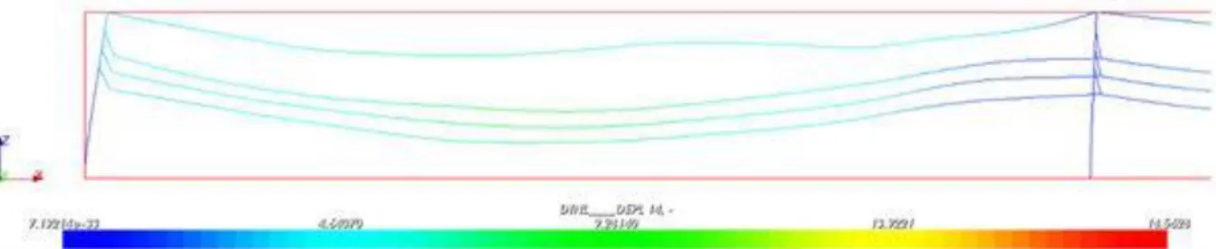
Dynamic analysis of transmission lines have mostly been used in the past to study cascading failures due to broken conductor events. Figure 4 shows an example of a dynamic analysis simulating broken conductors. The first finite element models to study this phenomenon were developed by Thomas and Peyrot [14]. McClure and Lapointe [15] used a commercial software to perform such studies and allowed to include a more precise definition of the structure’s model. Kempner [16] also used a dynamic model, in combination with small scale experimental tests, to evaluate a design philosophy
6
for failure containment. More recently, Bérubé [17] introduced material non-linearity in the behaviour
of the structures during cascading events.There is a common agreement that the numerical tools now
available can be used to successfully reproduce the dynamic behaviour of transmission lines in the case of broken conductor events [18]. Dynamic analysis can also be used to study wind, ice shedding, or seismic effects.
Figure 4: Example of a dynamic analysis simulating broken conductors
Most considerations discussed for static analyses also apply to dynamic analyses. In dynamic analyses, special care must be taken to correctly evaluate mass distribution, stiffness and damping of the structure. Damping is particularly difficult to evaluate. Measurements and discussions on this subject are presented in the literature [19-20]. An intermediate step in performing a dynamic analysis is normally to evaluate frequencies and mode shape of the system. This step helps to verify that the dynamic behaviour of the structure is reproduced adequately. Modal superposition is sometimes used to evaluate the response of structures to dynamic loading. However, this method is limited to linear analyses. Direct integration methods such as Newmark or HHT-alpha are used for nonlinear analyses because they allow actualizing matrices when solving the equation of movement at every time step. These methods can however become computationally intensive when using a nonlinear behaviour (sometimes causing many iterations per time step) and a large number of DOFs. Hence, in the case of nonlinear analysis, it is normally recommended to simplify the tower model and focus on reproducing correctly the global dynamic behaviour of the tower and overall transmission line system. Dynamic analyses will normally include cables because there will be interaction between the cable and tower structures. Because cable analysis needs to consider geometric non-linearity, nonlinear dynamic analysis is almost always used for studying the dynamic behaviour of transmission lines. Material non-linearity will typically only be included if the ductile behaviour of some component, used for example with the objective of dissipating energy during a cascading event, is studied.
HYBRID SIMULATIONS
Even with advanced models, the ultimate capacity and failure mode of transmission towers remain difficult to identify numerically and experimental tests are often required. On the other hand, the civil engineering field has seen over the last decades the development of a new testing technique that includes both experimental and numerical methods. This technique, called hybrid testing, involves the experimental testing of a sub-structure and the interaction during the test with a numerical model of the complete structure. This type of technique was mostly developed for the application of dynamic analysis of buildings and bridges under the action of seismic loads. It is therefore a dynamic analysis method, but it can be adapted to static analyses. Typically, one part of the structure is tested at the laboratory and the whole structure, except for the properties well represented in the lab (the mass, damping and stiffness for full dynamic testing or the stiffness for static/quasi-static testing) is included in the numerical model. A load is applied in the numerical model at the first time step. The model yields a displacement at the interface with the experimental sub-structure. This displacement is applied at the lab and then the restoring forces obtained are sent back to the model. Then, the second time step can be evaluated and the procedure continues until the loading sequence ends. To avoid numerous iterations between the numerical model and the physical model, an explicit integration scheme is used. In recent works performed at Université de Sherbrooke, the hybrid technique was adapted to lattice towers to evaluate buckling modes and ultimate capacity. A buckling analysis and a static analysis of
7
the complete tower were used to identify a sub-structure to test experimentally that could reproduce the same modes and capacity as evaluated by the complete numerical model (see Figure 3b). Then hybrid tests were performed with a section of the lattice tower at the laboratory and the rest of the tower in the numerical model. Finally, experimental tests were performed on the complete tower to serve as a validation point for the hybrid simulations. All analyses (numerical, hybrid, experimental) were performed on a structure taken from a real transmission tower but transferred to a reduced 1:4 geometrical scale. Figure 3c shows the setup used to apply displacements and measure forces at the tower section at the laboratory. Results for the hybrid tests showed close agreement with the results for the complete tower experimental tests [21]. Further development and validation of the method is ongoing at Université de Sherbrooke, but it is expected that hybrid tests could provide an alternative to advanced numerical models and full-scale testing.
CONCLUSIONS
This paper reviews recent advances in the use of advanced modelling methods for the application of steel lattice towers. It explains the types of elements, behaviour law, and type of analysis that could be used. It also presents briefly the method of hybrid simulations and how it could be used for lattice towers.
Numerical tools to perform advanced numerical analyses of lattice towers are now widely available and well-documented. However, one needs to choose wisely the modelling strategy and hypotheses to suit the problem studied. Unnecessary complexity of a model is normally avoided because it increases the number of assumptions and could lead to additional model uncertainty. When complex models are required, they should always be validated with simpler numerical models, and if possible, with experimental tests. Also, fabrication and erection tolerances could have an impact on the tower behaviour and these needs to be considered in the interpretation of results. Nevertheless, in many cases, advanced numerical models represent a powerful tool for the analysis of lattice towers and could lead to a reduction or an optimization of the need for full-scale testing.
Future works needed include the simplification and speeding up of model building methods. Hybrid simulations also need further development and validation before its use can be generalized to lattice tower applications. Finally, advanced modeling techniques continuously need to be validated with results from full-scale tower tests.
ACKNOWLEDGEMENTS
The authors would like to acknowledge the financial support of Hydro-Québec, RTE, and the National Sciences and Engineering Research Council of Canada (NSERC). The contribution of the following engineers and researchers from Hydro-Québec, RTE and Université de Sherbrooke to the development of advanced knowledge on numerical modelling and hybrid simulations of lattice towers is also acknowledged: Alex Loignon, Pierre-Luc Bouchard, Louis-Philippe Bérubé, Charles-Philippe Lamarche, Alexis L-Desrochers, and Hervé Ducloux.
BIBLIOGRAPHY
[1] Working Group SC 22-08 CIGRE. “An experiment to measure the variation in lattice tower design” (Electra number 138 October 1991 pages 83-110)
[2]
Working Group B2-08 CIGRE. “Influence of the hyperstatic modeling on the behavior of
transmission line lattice structures” (Brochure number 287 August 2009, 235 pages)
[3]
J
.G.S. da Silva, P.C.G. da S. Vellasco, S.A.L. de Andrade, M.I.R. de Oliveira “Structuralassessment of current steel design models for transmission and telecommunication towers” (Journal of Constructional Steel Research Vol. 61, 2005, pages 1108–1134)
[4] N. Prasad Rao, V. Kalyanaraman “Non-linear behaviour of lattice panel of angle towers”
8
[5] S. Kitipornchai, S.L. Chan “Nonlinear finite element analysis of angle and tee beam-columns”
(ASCE Journal of Structural Engineering Vol. 113, 1987, pages 721–739)
[6] P.-S. Lee, G. McClure “A general three-dimensional L-section beam finite element
for elastoplastic large deformation analysis” (Computers and Structures Vol. 84, 2006, pages 215–229)
[7] P-L Bouchard “Calcul de la capacité de pylônes à treillis avec une aproche stabilité (Master thesis, Université de Sherbrooke, Canada, 2013)
[8] S. Kitipornchai, A. Al-Bermani, A.H. Peyrot “Effect of bolt slippage on ultimate behavior of
lattice structures” (ASCE Journal of Structural Engineering Vol. 120, 1994, pages 2281–2287)
[9] W.Q. Jiang, Z.Q. Wang, G. McClure, G.L. Wang, J.D. Geng “Accurate modeling of joint effects
in lattice transmission towers” (Engineering Structures Vol. 33, 2011, pages 1817–1827) [10] C.O. Rex, W.S. Easterling “Behavior and modeling of a bolt bearing on a single plate” (ASCE
Journal of Structural Engineering Vol. 129, 2003, pages 792–800)
[11] F. Albermani, S. Kitipornchai, R.W.K. Chan “Failure analysis of transmission towers” (Engineering Failure Analysis Vol. 16, 2009, pages 1922–1928)
[12] P.-S. Lee, G. McClure “Elastoplastic large deformation analysis of a lattice steel tower structure and comparison with full-scale tests” (Journal of Constructional Steel Research Vol. 63, 2007, pages 709–717)
[13] L. Kempner Jr, W. H. Mueller III, S. Kitipomchai, F. Albermani, R. C. de Menezes, J. BGF da Silva “Lattice transmission tower analysis: beyond simple truss model” (Electrical
Transmission in a New Age, Ed. D.E. Jackman, 2002)
[14] M. Thomas, A.H. Peyrot “Dynamic response of ruptured conductors in transmission lines” (IEEE Transactions on Power Apparatus and Systems, Vol. PAS-101(9), 1982, pages 3022-3027)
[15] G. McClure, M. Lapointe “Modeling the structural dynamic response of overhead transmission lines” (Computers and Structures Vol. 81, 2003, pages 825-834)
[16] L. Kempner Jr “Longitudinal impact loading on electrical transmission line towers: a scale model study” (PhD thesis, Portland State University, Unites States, 1997)
[17] L-P Bérubé “Effets de l'ajout d'un mécanisme ductile à la console sur la réponse d'un pylône aux bris de conducteurs” (Master thesis, Université de Sherbrooke, Canada, 2012)
[18] Working Group SC 22-22 CIGRE. “Mechanical security of overhead lines - Containing
cascading failures and mitigating their effects” (Brochure number 515, October 2012, 80 pages) [19] M.J. Glanville, KCS Kwok, R.O. Denoon “Full-scale damping measurements of structures in
Australia” (Journal of Wind Engineering and Industrial Aerodynamics, Vol. 59, 1996, pages 349-364)
[20] J-Y Taillon, F. Légeron, S. Prud'homme “Variation of damping and stiffness of lattice towers with load level” (Journal of Constructional Steel Research Vol. 71, 2012, pages 111–118) [21] A. Loignon, F. Légeron, C.-P. Lamarche, S. Langlois “Développement d’un protocole d’essai
hybride par sous-structuration pour les pylônes à treillis” (Technical Report, Université de Sherbrooke, Canada, 2015
![Figure 3: a) Identification of a buckling mode on a tower [7]; b) Evaluation of an experimental substructure for hybrid simulations [21]; c) Test setup for hybrid simulations [21]](https://thumb-eu.123doks.com/thumbv2/123doknet/5004344.124651/6.892.106.783.463.926/figure-identification-buckling-evaluation-experimental-substructure-simulations-simulations.webp)