READ THESE TERMS AND CONDITIONS CAREFULLY BEFORE USING THIS WEBSITE. https://nrc-publications.canada.ca/eng/copyright
Vous avez des questions? Nous pouvons vous aider. Pour communiquer directement avec un auteur, consultez la première page de la revue dans laquelle son article a été publié afin de trouver ses coordonnées. Si vous n’arrivez pas à les repérer, communiquez avec nous à [email protected].
Questions? Contact the NRC Publications Archive team at
[email protected]. If you wish to email the authors directly, please see the first page of the publication for their contact information.
NRC Publications Archive
Archives des publications du CNRC
This publication could be one of several versions: author’s original, accepted manuscript or the publisher’s version. / La version de cette publication peut être l’une des suivantes : la version prépublication de l’auteur, la version acceptée du manuscrit ou la version de l’éditeur.
Access and use of this website and the material on it are subject to the Terms and Conditions set forth at
Damping of a floor sample
Rainer, J. H.; Pernica, G.
https://publications-cnrc.canada.ca/fra/droits
L’accès à ce site Web et l’utilisation de son contenu sont assujettis aux conditions présentées dans le site
LISEZ CES CONDITIONS ATTENTIVEMENT AVANT D’UTILISER CE SITE WEB.
NRC Publications Record / Notice d'Archives des publications de CNRC:
https://nrc-publications.canada.ca/eng/view/object/?id=20120820-c700-4953-b3e6-a94076db4049
https://publications-cnrc.canada.ca/fra/voir/objet/?id=20120820-c700-4953-b3e6-a94076db4049
National Research Conseil national
N21d
Council Canada de recherches Canadano.
985
c .
2
m
C
;
-1L-7-
-.
-r
DAMPING
OF A
FLOOR SAMPLE
by J. H. Rainer and G. Pernica
Reprinted from
Proceedings, ASCE Specialty Conference on
AMA.LYZED
Dynamic Response of Structuresheld 15
-
16 January 1981, Atlanta GA., p. 859-
873.
I
DBR Paper No. 985
Division of Building Research
I
Price
$1.25OTTAWA
8 "BLDG.
RES:
'
L I B R A R Y
82- 02-
09
B I B ~ I O T H ~ Q U '
Rech.
BStirr
C 6 ; Z C-
1 . C ) ANRCC
19457SOMMAIRE
Des e s s a i s v i s a n t
B
c o n n a r t r e l e comportement dynamique d e s p l a n - c h e r s o n t 6tC e f f e c t u e s s u r un p l a n c h e r 1 une s e u l e t r a d e d e 28 p i x 29 p i (8534 x 8839 mrn), c o n s i s t a n t e n une d a l l e de b e t o n c o m p o s i t e e t e n d e s p o u t r e l l e s d ' a c i e r t r i a n y l e e s . Ce document p o r t e p r i n c i p a l e m e n t s u r 1 ' Q t u d e d e s e f f e t s d e q u a t r e d t h o d e s d ' e s s a i d i f f e r e n t e s s u r l e s c o e f f i c i e n t s d ' a m o r t i s s e m e n t c o r r e s - pondant au mode f o n d a m e n t a l de v i b r a t i o n du p l a n c h e r . I1 a 6 t 6 demontre que l ' e s s a i d e s chocs d e t a l o n s couramment u t i l i s e p e r m e t t a i t d ' o b t e n i r d e s v a l e u r s d ' a m o r t i s s e m e n t modales i n v a r i a - blement s u p g r i e u r e s 1 c e l l e s o b t e n u e s p a r l a n o u v e l l e d t h o d e d ' e s s a i aux chocs du v i b r a t e u r , p a r l e b r u i t b l a n c ou p a r l e s e x c i t a t i o n s v i b r a t o i r e s e n regime s t a b l e . Ces v a l e u r s d ' a m o r t i s - sement s u p e r i e u r e s s o n t a t t r i b u a b l e s 1 l ' a m o r t i s s e m e n t suppl6men- t a i r e dC 1 l a p e r s o n n e q u i e f f e c t u e l e s chocs de t a l o n . L ' e f f e t d e s d i f f e r e n t e s m o d i f i c a t i o n s s t m c t u r a l e s e t a r c h i t e c t u r a l e s s u i v a n t e s s u r l e c o e f f i c i e n t d ' a m o r t i s s e m e n t fondamental a Q g a l e - ment 6 t 6 e t u d i 6 : v a r i a t i o n de l a b o r d u r e du p l a n c h e r , a j o u t d'un p l a f o n d suspendu ou d ' u n p l a f o n d e n p l a q u e s de p l b t r e , e t boulon- nage de bandes d ' a m o r t i s s e m e n t e n acier-n&oprSne 1 l a membrure i n f g r i e u r e d e s p o u t r e l l e s .Reprinted from the Proceedings of the Specialty Conference on DYNAMIC RESPONSE OF STRUCTURES
A ~ c ~ j ~ t l a n t a , GAj~anuary 15-1 6, 1981
DAMPING OF A FLOOR SAMPLE
By Johann H. Rainer, l Affil. ASCE, and Gerald ~ernica'
ABSTRACT
The dynamic behavior of floors was investigated by constructing a
28 ft x 29 ft (8534 x 8839 nun) single bay floor sample, consisting of a composite concrete slab and open-web steel joists. This paper is primarily concerned with an examination of rhe effect of four different
test methods on the modal damping ratios determined for the fundamental
mode of vibration of the floor sample. It
was
found that the commonly used heel impact test gave consistently higher values of modal damping than a new shaker impact test, white noise or steady state shaker excitations. The higher damping values were a result of the additional damping contributed to the floor sample by the person performing theheel impact. The effect on the fundamental damping ratio of the follow- ing structural and architectural modifications to the Floor sample were
also investigated: varying the edge conditions of the floor sample, adding
a
suspended ceiling or a gypsum board ceiling, and, bolting steel-neoprene damping strips to the bottom chord of the joists. INTRODUCTIONDynamic properties of floors have received considerable attention lately because many floors have exhibited unsatisfactory vibration behavior. More efficient designs and higher strength materials tend to make these components softer and lighter and thus more sensitive to vibration sources such as persons walking, mechanical equipment, and road and rail traffic. To arrive at acceptable designs or appropriate remedial measures, various criteria for floor vibrations in residential buildings have been proposed. A number of these have been summarized and compared by 1,lurray. (6)
Damping is one of the most important parameters that affects floor vibrations. Highly damped floors are rarely cause for complaint; those with low damping are likely to be troublesome. In the former, vibra- tions caused by footsteps die out quickly, but in the latter they persist and can build up and propagate from the source to adjacent regions of a floor system. The amount of damping in a floor has to be determined by measurements since it cannot as yet be reliably computed or predicted. It is therefore important that test methods give
consistent and reproducible results. In this investigation it was found that the values of damping determined from measurements can differ
l~esearch Officers, Noise and Vibration Section, Division of Building Research, National Research Council of Canada, Ottawa, Ontario KIA OR6
860 DYNAMIC RESPONSE OF STRUCTURES
greatly depending on the experimental procedure. Reasons and explana- tions for these differences are presented as well as damping ratios for several floor and ceiling configurations. The majority of the results only deal with the fundamental mode of the floor sample.
DESCRIPTION OF FLOOR SAMPLE AND INSTRUMENTATION
The experimental floor sample consisted of six 18-in. (457-mm) deep
open web steel joists forming a composite construction with a 3-in.
* I
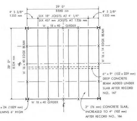
(76-mm) concrete slab. The sample had a total width of 29 ft (8840 mm)and a span of 28 ft (8534 mm). The shoes of the joists rested on the top flange of the end girders which in turn were supported by four corner steel columns. The columns were joined by edge beams parallel to the joists (Fig. 1). After record* No. 147, a 6 - x 9-in. (152 x 229-mm) concrete stiffening beam was added on the underside of the slab normal to the joists, as indicated by the dotted lines in Fig. 1. After record No. 166, a 1-in. (25-mm) concrete topping was applied to the concrete slab. The joists were instrumented with strain gages and accelerometers were attached to the top of the slab. The accelerometer stations are shown in Fig. 2, labelled 1 to 28; not all were used for every test. Transducer signals were fed into signal conditioners and three 7-channel
FM magnetic tape recorders. A portable spectrum analyzer, strip chart
~
recorder, and oscilloscope proved invaluable in assessing the quality of 1the signals and in providing partial answers as the test progressed. An electrodynamic shaker**,was the exciter. An external, band-limited white noise source, sinusoidal signal oscillator and a variable d-c supply I
provided the desired inputs and offset positions for the shaker
armature. The locations where the floor sample was excited are shown in Fig. 2, labelled A to E.
METHODS OF DYNAMIC TESTING
Two impulse methods and two continuous excitations were employed to test the floor sample. Heel impact and shaker impact were the impulse methods; continuous excitations were white noise and steady-state shaker tests.
Heel Impact. - In the heel impact test, a person weighing approxi- mately 170 lb. (77 kg) shifts his weight onto the balls of his feet
(thus raising his heels approximately 2 in. (50 mm) off the floor) and then suddenly shifts the body weight onto his heels and impacts the floor. This test has been widely used in floor vibration studies and was incorporated in floor vibration criteria (1, 4) because it is simple, relatively reproducible, and readily available. The impulse has a roughly triangular shape and lasts 50 ms. (5) The initial peak acceleration amplitude is obtained from the resulting free vibrations of the floor and the damping value is calculated from the rate of decay. Filtering is usually required to eliminate vibration components other than those for the mode of vibration that is of interest. For the
* A sequential numbering scheme was used during testing.
**
Type "Electro-seis" Model 113, manufactured by Acoustic Power Systems, Inc., Anaheim, California.FLOOR SAMPLE DAMPING
4' 5 3/8" 4' 5 3/8"
SIX 1 8 JOISTS AT 4' 1/4" 1355 rnm
6 " x P' (152 n 22P m m ) DEEP CONCRETE BEAM ADDED UNDER
SL4B AFTER RECORD
NO. 147 W 18 x 40 GIRDER
W 8 x 24 (1 829 rnm) 3" '66 mm) CONCRETE SLAB, COLUMNS 6' HIGH INCREASED TO 4" (102 mm)
AFTER RECORD N O . 166
X TEMPORARY JACK SUPPORTS FIG. 1-Layout of floor sample
FIG. 2-Locations of accelerometer stations ( 0 ) and dynamic force application ( )
862 DYNAMIC RESPONSE OF STRUCTURES
fundamental mode, peak floor accelerations from the heel impact were approximately 3 to 4% g.
Shaker Impact.
-
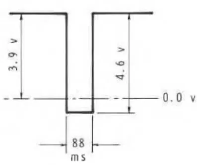
The armature of the shaker was used as a mass that was impacted onto the base of the shaker frame and thence onto the floor. The base of the shaker frame was covered with a 3-in. (6-mm) cellular rubber pad to cushion the impact of the armature. By trial-and-error, a rectangular voltage pulse from a pulse generator was selected to give suitable amplitude and duration of impulse. (The voltage input is shown in Fig. 3 and the resulting armature acceleration pulse in Fig. 4.) The duration of the impact can be seen to be approximately 7 ms. Lift-off of the armature was achieved before multiple rebounds could occur. A typical filtered impulse response of the floor sample is shown in Fig. 5, from which initial peak amplitudes and damping ratios from the decay rates were obtained. Initial amplitudes of floor vibrations from the shaker impact were 1 to 1.5% g for the fundamental mode.After several thousand impacts this apparent "abuse" of armature impacts has not caused any deterioration in the shaker's performance or its physical characteristics.
White Noise. - The signal from a band-limited white noise source, either from 0 to 25 Hz, or 0 to 50 Hz, was fed to the power amplifier of the shaker. Floor response and shaker armature acceleration were recorded for 20 min. Discrete Fourier amplitude spectra were then computed with Hanning weighting and the spectra averaged over 10 min. with analysis bandwidths of 60 and 150 mHz. Damping was computed from the half-power bandwidth method, which for Fourier spectra corresponds to the frequencies at 0.707 times the amplitude of the resonance peak. As the acceleration spectrum of the shaker output was held constant over a wide frequency range, relative spectral peak amplitudes also provide a measure of change in damping as floor modifications are examined. This is demonstrated in Figs. 6 and 7. The damping ratios for any mode are inversely proportional to the resonance amplitudes for that mode. But if the modification is accompanied by a change in the modal frequency, w, then a correction factor has to be applied to the damping ratio, 6, since for a mode, 6 = C/(2Mw), where C is the damping coefficient and M the modal mass. For constant values of C and M, the damping ratio is seen to be inversely proportional to the modal frequency.
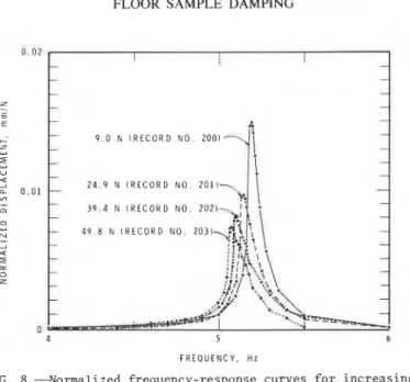
Steady State. - The shaker was driven by a constant amplitude sinusoidal voltage from a push-button signal oscillator. The vibration response of the floor was monitored on a strip chart recorder so that suitable frequency increments could be selected to define the frequency response curve adequately. The frequency was incremented once the response from the previous frequency had stabilized. This proved difficult to achieve on the steep ascending portion of the resonance curve, where a frequency increment held for over 1000 cycles still did not achieve full amplitude stability. Elsewhere the peak amplitudes stabilized in less than 300 cycles. Four peak force levels were used: 2.02 lb (9.0 N), 5.60 lb (24.9 N), 8.84 Ib (39.4 N), and 11.2 lb
(49.8 N). The resulting plots of frequency response were normalized relative to shaker force (Fig. 8).
FLOOR SAMPLE DAMPING
FIG. 3.Yoltage pulse to shaker
FIG. 4.--Measured acceleration of shaker armature (0.01 s/division)
FIG. 5.-Typical impulse decay curve (Station 3,
864 DYNAMIC RESPONSE OF STRUCTURES
,*...
B A R E F L O O R ( R E C O R D 7 9 1 F L O O R W I T H S U S P E N D E D 3 - 5 C E I L I N G ( R E C O R D 8 6 ) :1. .
. .
..
2-
. .
. .
. .
M O D E 1 f i-
::,.
M O D E 2 : i. .
. .
.
.
. .
. .
.
. .
.
: :.
.
: : I F R E Q U E N C Y , H z~
FIG. 6.---Effect of suspended ceiling on Fourier amplitude spectra of floor response (Station 3, white noise shaker excitation at E, end girders fully supported) 4I
WI
0 3 BARE FLOOR I- (RECORD NO. 169) 3-
1 PERSON AT A 2 - (RECORD NO. 171) 1-
\
(RECORD NO. 172) 0-
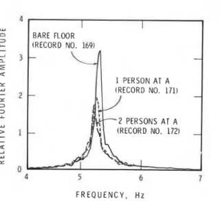
F R E Q U E N C Y , H zFIG. 7.---Effect of people on Fourier amplitude spectra of floor response (Station 3, white noise shaker excitation at (A)
FLOOR SAMPLE DAMPING I -
t
I - - - - - - - A-
- 9 . 0 N I R E C O R D N O . 2 0 0 1 1 , ' - -I
--
--
- 2 4 . 9 N [ R E C O R D NO. 2011- - - - + 3 9 . 4 N I R E C O R D NO. 2 0 2 ) --
- 4 9 . 8 N ( R E C O R D N O . 2 0 3 1 - - - --
-
-
-
-
- A A 4 5 6 F R E Q U E N C Y . H zFIG. 8.--Normalized frequency-response curves for increasing
force levels
F R E Q U E N C Y . H z
FIG. 9 . 4 f f e c t of steel-neoprene strips on Fourier
amplitude spectra of floor response (Station 3, white noise shaker excitation at E, girders fully supported
866 DYNAMIC RESPONSE OF STRUCTURES VARIATION OF FLOOR PARAMETERS
The effect of the following variables on the damping ratio of the fundamental mode is presented: simply and fully supported end girders; suspended ceiling; gypsum board ceiling; and steel-neoprene damping strips applied to joists.
Simply and Fully Supported Girders and Beams. - The floor sample was constructed with edge beams and end girders spanning between the four corner columns, i.e., the simply supported condition. For some of the measurements the vertical motion of the end girders and/or the edge beams was restrained by temporary jacks, 3 per side, shown by the symbol
X in Fig. 1. This is termed the fully supported condition for beams or girders.
Suspended Ceiling.
-
The suspended ceiling consisted of 2 ft x 4 ft (610 x 1220 mm) press-fibre panels laid in an interlocking network of inverted aluminum T bars which were suspended by wires from the lower chords of the joists. Each panel weighed 7.25 Ib (3.29 kg). To simulate the additional weight of recessed lighting fixtures, a 20-lb (9.07-kg) bag of lead shot laid over 2 angle-irons weighing 8 lb (3.63 kg) was placed on every third panel of two rows of the suspended ceiling.Gypsum Board Ceiling. - Sheet metal channels were wired tightly onto the underside of the joists and sheets of f-in. (12.7-mm) gypsum board 4 ft x 8 ft(1220 x 2440 nnn) were screwed onto the channels. The ceiling terminated at the beams and girders.
Steel-neoprene Damping Strips on Joists. - A 3-in. (76-mm) wide sandwich was constructed of strips of neoprene, in. (6.3 mm) thick, glued between f-in. (6.3-mm) and f-in. (12.7-mm) strips of steel by means of a rubber glue. The &-in. (6.3-mm) steel strip was bolted onto the underside of the joist by means of f-in. (12.7-mm) diameter bolts inserted between the two joist angles at intervals of roughly 2 ft (610 mm). Holes of 1;-in. (32-mm) diameter through the lower steel strip and the neoprene permitted the lower steel plate to restrain the neoprene. Thus longitudinal shear strains were induced in the neoprene core as the joists deflected. The sandwich dimensions were determined according to a previous theoretical investigation into the action of damping strips (2) although the mechanical properties for the present sandwich construction were dictated by availability of stock items. The manufacture of these strips proved to be time consuming and some local delamination occurred near the bolt locations, where the upper steel plate was permanently deformed by the bolt tension.
RESULTS
The damping ratios for the fundamental mode of the floor sample as obtained from the four test methods are presented in Tables 1 and 2. For the impulse methods the damping ratios were computed using the logarithmic decrement of the first 20 cycles of the filtered accelero- meter signals, except where otherwise noted. For the white noise and steady state results the half-power bandwidth method was employed. The numbers used to identify the various diagrams and sets of damping values in the tables are the record numbers associated with the measurement
868 DYNAMIC RESPONSE OF STRUCTURES TABLE 2.-Damping Description of Floor and Modifications a) floor without modifications b ) suspended ceiling with "lights" c) gypsum board ceiling d) steel-neoprene damping strips a) floor without modifications i) end girders and edge beams fully supported ii) only end
girders fully supported b) suspended ceiling with "lights" C) gypsum board ceiling d) steel-neoprene damping strips * Analysis bandwidth = 0.060 Hz
** Extrapolated from comparisons between other cases of shaker impacts and heel impact tests
Ratios for Various Floor Modifications, 3 in. (76.2 mm) Slab
Natural Frequency, Mode 1 Hz pp Damping Shaker Impact Record Number, Loca- tien of Force
A. Simply supported beams
6~ '6 ratio, 6, % of Heel Impact Record Number, Loca- t ion of Force critical White Noise, from (0.41** 0.62 0.44 0.76 and girders 135. A 98. A B C D 103, A B C D 119. A sup:~orted, 77. A B C D 112, A B C D 93, A B C D 108, A B C D 114, A C 5.41 5.30 5 . 3 8 5 . 8 double 6 . 2 peak 8 ha1 f bandwidth* Record Number, ~ o c a - tion of Force 146, E 97, E 100, E 118, E noted 111, E 94, E 106, E 113, E 0.91 1.10 0.90 0.88 0.85 0.98 0.97 0.88 0.81 0.97' except as 1.19 0.85 0.82 0.72 1.25 0.95 0.86 0.65 1.67 1.55 1.17 1.06 1.30 1.18 1.07 0.96 1.74 1.65 99, E 104, E 121, -power 6~ % 0.37 0.47 0.38 0.20 0.58 0.40 0.95
B. End girders fully
6.4 6 . 3 8 6.20 6.36 7. R 76, E 92, E 109, E 115, E 0.37 (0.4)** 0.71 0.44 1.0
FLOOR SAMPLE DAMPING 869
procedure; the letter syn~bols refer to the location of dynamic force application (Fig. 2).
Damping for Simply and Fully Supported Girders.
-
From the results given in Table 2 A f o r the simply supported girders, and Table 2 B for the fully supported girders, it can be seen that except for one white noise comparison [record No. 111 in Table 20 vs. record No. 146 in Table ZA3 damping ratios for the siqly supported case are lower than for the fully supported one. This is contrary to what one might expect on acursory examination of damping in a single-degree-of-freedom equivalent
system. Since 6 = C/(ZMw), one might expect 0 to decrease
as
the frequency, w , is increased by supporting the girders. However, the increase in floor frequency is also accompanied by changes in M and C.The equivalent mass, M, is reduced due to changes in the mode shape and
the damping coefficient C is changed since damping mechanisms that are
1
associared with the g i r d e ~ motions are modified. Prediction of damping ratios corresponding to changes in structural configurations should therefore be approach4 cautiously. In most cases prediction of damping ratios may not be possible since changes in the damping coefficient Care not measurable or quantifiable.
Comparisons of Damping Ratios from Heel Impact, Shaker Impact and I White Noise Excitation. - Damping ratios from shaker impact and heel
impact tests differed substantially For the same floor configuration [Table I), This was recognized to be the result of the additional damp-
ing contributed to the floor sample by the person performing the heel impact. This is illustrated by comparing the damping ratios from rhe
shaker impacts, first on the empty floor, then with 1 person. 2 persons,
and sometimes 3 persons present. For the simply supported case the percentage
of
critical damping increased by approximately 0.3 per person for the 4-in. (102-mm) slab, 0.4 per person for the 3-in. (76-mm] slab, and by 1.0 per person for the 3-in. (76-mm) slab with supported girders. I This pattern of increased damping with increasing number of persons isevident from the heel impact tests. With the same number of people on the floor during shaker impact and heel impact tests damping ratios were comparable. A similar difference in damping values for the heel impact
l
and steady state shaker tests was found in a field test of a floor (7). I Another variable that affects the damping ratio as obtained from the
heel impact is the location of the person performing the test. Tables 2A
I and 20 show that the damping ratios from the heel impact decrease considerably as the impactor moves from locations A through D. This can be ascribed to a decreased effectiveness of the human "damper" as the modal amplitude of vibration decreases. It should be emphasized that this is not a phenomenon of the amplitude dependent damping mechanism of
I
the floor, but rather one of amplitude dependence of the human "damper"as it changes location relative to the modal deflection pattern of the floor. The influence of people on the damping level of floors has also been noted and described by Lenzen. (4)
The effect of humans on the damping level of the floor is also illus- trated by the white noise results where a decrease in the resonance peak indicates a proportional increase in the damping ratio. In Fig. 7 the ratio of decrease of the peaks is 1:0.64:0.58 showing ,; 56% increase in
870 DYNAMIC RESPONSE OF STRUCTURES
damping for 1 person and a further 10% increase for the second person.
The increase in damping ratio for the second person is smaller f o ~ white
noise than for the impact tests. One can attribute this to the fact
that a person finds it difficult to remain motionfess over an extended
period of time. Consequently some floor vibration will be induced by
involuntary movements of the subjects on the floor.
Steady State.
-
The results from the steady state tests presented inTable 1 and in the frequency response curves in Fig. 8 indicate a trend
of increasing damping ratios with increasing amplitude of vibration. The frequency response curves in Fig. 8 also show a reduction in
resonance frequency of 0.107 Hz as the vibration amplitudes a t resonance
increase from 0.0054 to 0.0148 in. (0.137 to 0.375 mm). The floor thus
exhibits the characteristics of a softening spring system. Such a system
can exhibit stability problems in the ascending partion of the resonance curve, giving rapid increases in amplitude for very small increases in
frequency. (3) The descending portion of the frequency response curve
is relatively higher than the ascending portion, also a typical charac-
teristic of softening sprinp, systems. Given such non-linear behavior, the half-power bandwidth method for calculating damping ratios is not strictly applicable. For small non-linearities, however, this should not introduce large errors and in Table 1 the damping ratios from the
frequency response curves are seen to be comparable to those obtained
from the shaker impact method. Whether this non-linear behavior is
present in the other floor configurations is not certain since only this one set of steady state tests was carried out.
White Noise Excitation.
-
Band-limited white noise, when applied tothe shaker, produced a random-type excitation with nearly constant force
output aver the selected frequency range. Natural frequencies and mode shapes were readily determined from the Fourier spectra of the ~esultiny!
t e s y n s e signals. Unfortunately, it was not as easy to obtain reliable
damping ratios from the half-power bandwidth method for this lightly
damped system.
As seen in Tables 1 and 2, damping ratios from white noise shaker tests are not fully consistent with the shaker impact or heel impact
tests. The overall trends
of
an increase in modal damping with anincrease TI the number of people on the floor, and an increaseindamping
with the steel-neoprene strips are present, but the degree of consis-
tency is not sufficient to permit their use in quantitative comparisons
of test methods or structural configurations.
For consistent results, the excitation needs to be stationary. which
means a relatively long recording time. The analysis should thm be carried out to sufficient resolution so that the bandwidth of the Fourier transform process is a small fraction of the half-power band-
width used to calculate the damping ratio. A high resolution analysis
may, however, accentuate small local nonuniformitjes in spectral
content of the excitation and thereby introduce a distortion in the
Fourier spectrum of the response.
Damping for Different Ceiling Types.
-
Damping ratios for the floorsample with two different types of ceiling are presented in Table 2A
FLOOR SAMPLE DAMPING 87 1
supported end girders. For both support conditions the suspended ceiling produced increases of 0.2 to 0.3 in the percentage of critical damping compared to that of the bare floor. The gypsum board ceiling, on the other hand, showed practically no increase in damping. Two possible causes suggest themselves. First, the large number of loose panels inserted into the T-frame of the suspended ceiling provides a horizontal source of energy dissipation along the edges of the T-bars as the floor vibrates up and down. Second, the suspended ceiling may act like a tuned damper and thereby reduce the floor motion. The more
I rigidly installed gypsum boards do not appear to offer the same opportu-
I ities for energy dissipation. The small increase in fundamental
I
contributes to the floor stiffness and as a consequence relatively less frequency of the floor sample indicates that the gypsum board actuallyenergy is dissipated by friction. The relative effectiveness of these two types of ceiling is opposite to that reported by Lenzen. (4) This would indicate that details of installation and construction of ceilings play a role in the mobilization of damping.
Steel-neoprene Damping Strips. - The steel-neoprene sandwich strips bolted to the lower chord of the steel joists increased the damping ratio of the floor sample by about 0.2% of critical for simply supported end girders and by about 0.5% of critical for the fully supported ones (Tables 2A and 2B). In addition, the steel-neoprene strips increased the fundamental frequency by about 20% (Tables 1 and 2). However, these changes in characteristics of the floor sample were still not sufficient to result in acceptable vibration behavior under footstep excitation. The effectiveness of these particular steel-neoprene sand- wich strips has thus been somewhat disappointing.
For the white noise tests, Fig. 9 shows that the strips reduced the root-mean-square acceleration by a factor of 4.7 for the first mode, and 2.0 for the second mode.
DISCUSSION
This floor sample was constructed to investigate the effect of various parameters on the dynamic characteristics of floors. Because the physical dimensions of the sample were limited, its behavior is not representative of multi-bay floor systems in buildings where adjacent panels and different support conditions yield additional sources of damping. The low level of damping of this sample, however, provided an opportunity to detect relatively small changes in damping with changes in floor configurations and experimental methods.
Even though the heel impact test does not yield the damping charac- teristics of an unoccupied structural floor system, it is the simplest
' and probably most realistic test method to be used in tests that involve
the reaction of people to floor vibrations, since at least one person has to be present on the floor to perceive the vibrations. However, for the application of floor vibration data to situations other than human '
perceptibility, such as placement of sensitive instrumentation or machinery, the heel impact test may overestimate the amount of damping present in lightly damped floors and thus give an erroneous assessment.
872 DYNAMIC RESPONSE OF STRUCTURES
The non-linear stiffness and damping characteristics of the floor sample were most distinctly portrayed by the steady-state tests. Non-linear effects were not discernible from the Fourier spectra obtained from the shaker impact, heel impact, or white noise tests. It should be noted, however, that for these three methods no special attempt was made to investigate non-linear behavior by varying the amplitude of floor excitation.
The non-linear behavior in this floor sample may in part be ascribed to the structural modifications made to the original floor, namely the
I
addition of the transverse 6 in. x 9 in. (152 x 229 mm) concrete beam~
and the 1-in. (25-mm) concrete topping. Both beam and topping showedsome cracks which would contribute to non-linear vibration behavior. I
CONCLUSIONS I
In a lightly damped system the damping ratios obtained from the heel impact test are larger than those from a shaker impact test or other shaker tests due to the additional damping contributed by the person performing the heel impact test. Increasing the number of persons present on the floor (up to 3 investigated here) results in a propor- tional increase in the measured damping ratios.
The damping ratio obtained from the heel impact test varies with the location of the impactor, being largest when the floor was impacted at the point of largest modal amplitude and decreasing as the modal amplitudes corresponding to the impact location decreased.
For the floor sample with structural modifications, the steady-state frequency response curves indicated an increase in damping ratios with increasing amplitudes of floor vibration. The same conclusion was reached when the damping ratio was evaluated by the half-power bandwidth method. The frequency response curves also showed a reduction in resonance frequency with increasing amplitude of floor vibration and, together with the shape of the frequency response curves, indicated a softening spring system.
With this floor sample, a suspended ceiling was found to provide more damping in the fundamental mode than a gypsum board ceiling. Higher levels of damping were achieved with steel-neoprene sandwich strips but neither the ceilings nor the sandwich strips provided what could be considered large increases of damping over those exhibited by the original bare floor.
ACKNOWLEDGEMENTS
This paper describes results obtained from a cooperative testing program involving Public Works Canada and the Division of Building Research of the National Research Council of Canada. The authors wish to thank all contributors for their help in this study.
FLOOR SAMPLE DAMPING 873
I
APPENDIX I. - REFERENCES1. Allen, D.E., and Rainer, J.H., "Vibration Criteria for Long-Span Floors," Canadian Journal of Civil Engineering, Vol. 3, No. 2,
June 1976, pp. 165-173.
2. Farah, A., Ibrahim, I.M., and Green, R., "Damping of Floor
Vibrations by Constrained Viscoelastic Layers," Canadian Journal of,
Civil Engineering, Vol. 4, No. 4, Dec., 1977, pp. 405-411.
3. Jacobsen, L.S., and Ayre, R.S., Engineering Vibrations, McGraw-Hill Book Co., Inc., New York, 1958, p. 286.
I
4. Lenzen, K.H., "Vibration of Steel Joist-Concrete Slab Floors,"AISC
Engineering Journal, Vol. 3, No. 3, July 1966, pp. 133-136. 5. Lenzen, K.H., and Murray, T.M., "Vibration of Steel Beam Concrete
Slab Floor Systems," Report No. 29, University of Kansas,
Lawrence, KA, 1969.
6. Murray, T.M., "Acceptability Criterion for Occupant-Induced Floor
Vibrations," Sound and Vibration, Vol. 13, No. 11, Nov., 1979, pp. 24-30.
7. Rainer, J.H., "Dynamic Tests on a Steel-Joist concrete-Sla6 Floor," Canadian Journal of Civil Engineering, Vol. 7, No. 2, June 1980, pp. 213-224.
This publication i q being distributed by the Division of Building R e s e a r c h of the National R e s e a r c h Council of Canada. I t should not be reproduced in whole o r in p a r t without p e r m i s s i o n of the original publisher. The Di- vision would be glad to b e of a s s i s t a n c e in obtaining s u c h permission.
Publications of the Division may be obtained by m a i l - ing the a p p r o p r i a t e r e m i t t a n c e ( a Bank, E x p r e s s , o r P o s t Office Money O r d e r , o r a cheque, m a d e payable to the R e c e i v e r G e n e r a l of Canada, c r e d i t NRC) t o the
National R e s e a r c h Council of Canada, Ottawa.
K1A
OR6.Stamps a r e not acceptable.
A l i s t of a l l publications of the Division i s available and m a y be obtained f r o m the Publications Section. Division of Building R e s e a r c h , National R e s e a r c h Council of Canada, Ottawa. KIA OR 6.
![[PDF] Formation général pour débuter avec le CMS Drupal | Cours informatique](data:image/gif;base64,R0lGODlhAQABAIAAAP///wAAACH5BAEAAAAALAAAAAABAAEAAAICRAEAOw==)