HAL Id: hal-01844813
https://hal.archives-ouvertes.fr/hal-01844813
Submitted on 19 Jul 2018
HAL is a multi-disciplinary open access
archive for the deposit and dissemination of
sci-entific research documents, whether they are
pub-lished or not. The documents may come from
teaching and research institutions in France or
abroad, or from public or private research centers.
L’archive ouverte pluridisciplinaire HAL, est
destinée au dépôt et à la diffusion de documents
scientifiques de niveau recherche, publiés ou non,
émanant des établissements d’enseignement et de
recherche français ou étrangers, des laboratoires
publics ou privés.
Internal stress reduction in filament wound composite
pipes by humid conditioning : numerical simulation
Frédéric Jacquemin, Alain Vautrin, Ronald Guillén
To cite this version:
Frédéric Jacquemin, Alain Vautrin, Ronald Guillén. Internal stress reduction in filament wound
composite pipes by humid conditioning :
numerical simulation.
International Conference on
Processing & Manufacturing of Advanced Materials (THERMEC’2003), 2003, Leganes, Spain.
�10.4028/www.scientific.net/MSF.426-432�. �hal-01844813�
Internal stress reduction in filament wound composite pipes
by
humid conditioning : numerical simulation
F. Jacquemin
1,A. Vautrin
2and
R.
Guillen
11
Laboratoire d'Applications des Materiaux
a
Ia Mecanique, IUT de Saint-Nazaire - Universite de Nantes, 44 600 Saint-Nazaire, France2
Mechanical and Materials Engineering Department, Ecole Nationale Superieure des Mines de Saint-Etienne, 42 000 Sant-Etienne, France
Keywords: Internal stress, hygrothermal treatment, filament winding process, polymer composite pipes.
Abstract. The paper introduces a new approach which tends to lower the internal stress state within composite pipe walls by using special post-cure hygrothermal treatment. Residual curing stresses in polymer composites are particularly critical in dry conditions, it is proved that an easy way to limit their effect on the material integrity is to introduce hygrothermal stresses. The residual stresses define the initial state of the pipe before it's service life. Usual ambient conditions generate internal stresses which add to the residual manufacturing stresses. It is shown that particularly hygrothermal conditions introduced just after the manufacturing can induce transient stresses which finally will reduce the global stresses. The proposed approach makes it possible to check the influence of time-variable process temperature and pressure, and hygrothermal in-service conditions on polymer matrix composites behavior.
Introduction
The composite pipes are usually manufactured by filament winding process. The filament winding process is commonly composed of three steps : (l) winding the composite tows onto a mandrel, (2) curing, and (3) cool-down and removal of the mandrel. After winding, the assembly composed of the mandrel and the composite pipe is introduced in an autoclave to cure the epoxy resin according to a prescribed temperature and pressure history [ 1]. The stress free state is supposed to be achieved at the cure temperature then there is no stress development prior to cool-down. In thin composites a uniform through-the-thickness temperature distribution assumption is justified. Such an approach is not appropriate for predicting the process-induced stresses in thick thermoset composites where complex temperature develops during the manufacturing process [2]. The residual stresses in the pipe wall, due to non-uniform temperature fields, are computed within the framework of thermo-elasticity. Special attention is then paid to the particular effect of the mandrel thickness on the residual stress development. When curing is completed, the mandrel is removed and the pipe is submitted to the environmental conditions. Ambient conditions generate internal stresses which add to the residual manufacturing stresses. Such residual stress growth may damage pipes manufactured by using thick mandrels. The scope of the paper is to show that the introduction of particular hygrothermal conditions just after the manufacturing process induce transient stresses which counteract the residual curing stresses.
Manufacturing process Temperature field.
We consider a pipe made up of n perfectly bonded plies, whose inner and outer radii are a and b respectively, manufactured by filament winding process onto a mandrel. Any ply i of it is a cylinder whose inner and outer radii are ri and ri+I respectively. The pipe and the mandrel are initially at the
by a coefficient of exchange h kept constant. The autoclave temperature T(t) follow the cure cycle. It is assumed that no heat transfer occurs at the inside of the mandrel [3]. Conditions of continuity of the temperature and heat flux are prescribed at ply-interfaces.
The temperature field in ply i (the internal ply being the mandrel) is solution of the equation set bellow, with Fourier's equation (1) and boundary and initial conditions (2) :
2
ori
a
Ti 1aTi
.
- = k · ( - - + - - ) a<r<b J= 1 ton
at
Iar2
r fu ' '(1)
Ti(ri, t) = Ti+l (ri, t)
A· 3Ti(ri,t) =A 3Ti+l(ri,t)
1
ar
HIar
aT1(a,t) = 0ar
(2)aTn~b,
t)- h(T(t)- Tn (b, t)) = 0 Ti(r,O) = T0The thermal field, in the composite pipe during the cool-down, is determined by using a finite difference scheme.
Process-induced stresses.
The residual stresses for every ply at any time are calculated by using the classical equations of solid mechanics : constitutive laws of thermoelastic orthotropic materials (3), strain-displacement relationship, compatibility and equilibrium equations and boundary conditions [ 4].
a= L: (E- a(T- To)) (3)
At the beginning of the cool-down, let us consider a stress-free state. Moreover a and L,
respectively the tensors of thermal expansion coefficients and stiffnesses, are assumed to be constants.
The axial and circumferential components of the displacement field of the ith ply, respectively u and v, are then express (4):
(4)
The temperature field is determined by using a finite difference scheme. To propose a close form solution of the displacement, we subdivide the mandrel-composite structure and assume on each subdivision a parabolic temperature field (6) :
T 1 =A r1 2 +B r+C 1 1 (6)
Thus, we obtain the radial component of the displacement field, solution of the equation (5), for each subdivision : (K1 -K2)T0r Lee Lrr(l-
L·-)
rr (7)Finally for n-layer tube the displacement field depends on 4n constants (R1, R2, R3 and~) to be
determined. The constants are calculated from the following conditions : continuity of the displacement components at each interply; global force balance of the cylinder; continuity of the normal stress at each interply and its nullity on the internal surface and an autoclave pressure applied on the external surface.
Internal stresses generated by the ambient conditions
When curing is completed, the mandrel is removed and the pipe is submitted to the environmental conditions. Ambient conditions generate internal stresses which add to the residual manufacturing stresses. The internal stresses in the pipe wall are computed within the framework of hygro-thermo-elasticity. We consider an orthotropic hygrothermoelastic constitutive law, strain-displacement relationship and compatibility and equilibrium equations [ 4]. To calculate the unknown constants, 4n constants for n-layer tube, we applied identical relations to the determination
of the process-induced stresses but with the nullity of the normal internal stress on the two lateral
surfaces of the composite pipe. Example
We consider a thick walled carbon-epoxy (T300/5208) pipe made up of 20 plies of equal thickness, the inner and outer radii being respectively 75 mm and 90 mm. The lamination sequence (corresponding to high buckling strength) studied is [906/60/-60/(30/-30)5/60/-60/902]. An aluminium mandrel 6061-T6 is used for the manufacturing process [5]. The mechanical properties
of the composite (T300/5208) and aluminium mandrel are respectively presented in Tables 1 and 2.
The cure temperature and room temperature are 180 °C and 20 °C respectively. The cooling rate is 3°C/min. The thermal properties of the composite (T300/5208) and aluminium mandrel are presented in Table 3. The thickness of the mandrel hm is chosen to be equal to one-third, one-fifth, one-seventh or one-ninth of the total thickness h (mandrel+ composite).
Table 1 : Mechanical properties in the reference frame linked to the fibres (1 ,2,3) Material E, [Gpa] E2, E3 [GPa] v12, v13 v23 G12 [GPa] a1 [K1] a2, a3 [K1]
T300/5208 181 10,3 0,28 0,43 7,17 0,02.10-6 22,5.10-6 Table 2: Mechanical properties for aluminium mandrel (6061-T6)
Material E [GPa] v a [K-1
] Aluminium 72.5 0,3 23.6.10-6
Table 3: Thermal properties of the composite (T300/5208) and aluminium mandrel (6061-T6) Materials A. [W.m-1 K 1
] p [kg.m-3] c [J.kg-1.K1] h [W.m-2Y1]
T300/5208 0,7 1590 857 50
Aluminium 180 2700 964
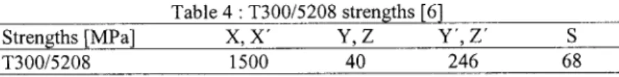
The use of the Tsai strength criterion allows us to estimate the internal stresses versus the ply resistance. The tensile failure stresses in the longitudinal, normal and transverse direction denoted respectively X, Y, Z are reported in Table 4. The corresponding failure stresses for compression are
X, Y', Z' and S stands for the plane shear failure stress. These strengths are assumed not to depend on humidity and temperature. R, the strength factor derived from the Tsai strength criterion, stands
for the ratio between the ultimate stress and the applied stress. Therefore, the failure occurs when R
is less or equal to 1.
Table 4: T300/5208 strengths [6]
Strengths [MPa] X, X' Y, Z Y', Z'
s
T300/5208 1500 40 246 68
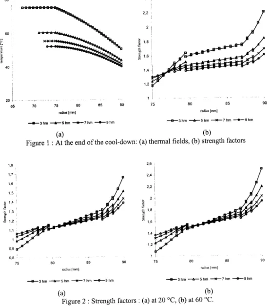
The cool-down from the cure temperature (180
aq
to the room temperature (20 °C) for a cooling rate of 3°C/min takes 3200 s. The thermal fields at the end of the cool-down, for different thickness of the mandrel, are plotted in Fig. l(a). There is a considerable lag between the tube and autoclave temperatures, especially at the inner surface where no heat transfer occurs. Thermal gradients are growing functions of the mandrel thickness. Fig. 1(b) shows that the minimum strength factor is reached at the inner surface (90° layer). Even if the strength factor remains encouraging for the composite plies, we recommend the utilization of thin mandrel which one the strength factor is higher on the inner surface.When curing is completed, the mandrel is removed and the pipe is submitted to the environmental conditions : a temperature of 20 °C and a relative humidity of 50 %. Since the temperature diffusion speed exceeds the moisture diffusion one by several orders, it is reasonable to assume that a uniform temperature of 20
ac
is reached in the composite pipe without change of the moisture concentration (dry conditions). This change of temperature induced internal stresses which add to the residual manufacturing stresses. Fig. 2(a) shows the corresponding strength factor. Critical values of the strength factor, less to 1, are reached for the pipe manufactured by using thick mandrels : one-third and one-fifth of the total thickness. To reduce the internal stress state a humid conditioning, temperature of 60ac
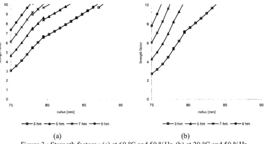
and a relative humidity of 50 %, is introduced before the placement at ambient conditions of the composite pipe. We check, in Fig. 2(b ), that the change in temperature, from the temperature at the end of the cool-down (Fig. 1) to a uniform temperature of 60 °C, no involves damage in the composite pipe for all the mandrels considered. The change of the moisture concentration from the dry conditions to a relative humidity of 50 % produce compressive stresseswhich induced a growth of the strength factor (plotted in Fig. 3(a) for values less than 1 0). Fig. 3(b) depicted the strength factor, for values less than 10, when the composite pipe is placed in the environmental conditions. The strength factor undergoes important gradients and it reaches a minimum value of about 2,75 on the inner surface. Finally, the material integrity is preserved by introducing transient hygrothermal stresses.
80 60 I 40 : 20
l-65 1,8 1.6 1,3 1,1 0,9 0,8 . -75 70 75 80 85 90 radius [rrun] 2.4 ' 2.2 . ~ 1,81' <! ~ 'J
1,6i
1,2 I 1 I 75 80 85 radius[mm] -e-3hm _.,_5hm ~7hm -+-9hm - B - 3 hm ---6--5 hm ---tt-7 hm --+-9 hm (a) (b)Figure 1 : At the end of the cool-down: (a) thermal fields, (b) strength factors
2.6 2,4 2,2 ~ 2 ; <! t 1,8
i
1.6 1,4 1,2 ' 80 85 90 75 80 85 radius[mm] radius[mm] --B--3 hm ---6-5 hm ---M-7 hm --+-9 hm - e - 3 hm ---6--5 hm ---M-7 hm --e--s hm (a) (b)Figure 2: Strength factors: (a) at 20 °C, (b) at 60 oc_
90
2 ' I I 0 : 75 80 85 90 75 80 85 90 radius[mm] radius[mm] --&-3 hm _,..__5 hm --*'-7 hm ---+--9 hm - a -3 hm ----6--5 hm ---M-7 hm --&-9 hm (a) (b)
Figure 3 :Strength factors: (a) at 60
oc
and 50 %Hr, (b) at 20oc
and 50 %Hr.Conclusion
The problem of internal stresses induced by processing and ambient conditions in thick polymer composite pipes is examined. The paper present an approach that allows to reduce the internal stress state and prevent process-induced damage by using a post-cure hygrotherrnal treatment. The growth of internal stresses, induced by the ambient conditions after the manufacturing process, can lead to
damage for thick composite pipes. It is shown that the introduction of a humid conditioning, before
the placement in the ambient conditions of the composite structure, involves a reduction of the internal stresses. The influence of the mandrel thickness on the residual stress development is investigated. It is emphasized that curing stresses can be manipulated by choosing tailored mandrel thickness.
References
[1] S.Y. Lee, G. S. Sringer and E.P. Calius: Jour. ofComp. Mater. Vol. 24 (1990), p. 1270. [2] T.A. Bogetti and J.W. Gillespie: Jour. ofComp. Mater. Vol. 26 (1992), p. 626.
[3] M.R. Wisnom, L.G. Stringer, R.J. Hayman and M.J. Hinton: Proc. ICCM 12, Paris (1999). [4] F. Jacquemin and A. Vautrin: Comp. Sci. and Tech. Vol. 62 (2002), p. 567.
[5] Y.K. Kim and S R White: Mech. ofComp. Mater. and Struc. Vol. 5 (1998), p. 327. [6] S.W. Tsai: Composite design (Think composites, 1987).