Publisher’s version / Version de l'éditeur:
Journal of Membrane Science, 100, 3, pp. 183-192, 1995-04-28
READ THESE TERMS AND CONDITIONS CAREFULLY BEFORE USING THIS WEBSITE. https://nrc-publications.canada.ca/eng/copyright
Vous avez des questions? Nous pouvons vous aider. Pour communiquer directement avec un auteur, consultez la première page de la revue dans laquelle son article a été publié afin de trouver ses coordonnées. Si vous n’arrivez pas à les repérer, communiquez avec nous à PublicationsArchive-ArchivesPublications@nrc-cnrc.gc.ca.
Questions? Contact the NRC Publications Archive team at
PublicationsArchive-ArchivesPublications@nrc-cnrc.gc.ca. If you wish to email the authors directly, please see the first page of the publication for their contact information.
NRC Publications Archive
Archives des publications du CNRC
This publication could be one of several versions: author’s original, accepted manuscript or the publisher’s version. / La version de cette publication peut être l’une des suivantes : la version prépublication de l’auteur, la version acceptée du manuscrit ou la version de l’éditeur.
For the publisher’s version, please access the DOI link below./ Pour consulter la version de l’éditeur, utilisez le lien DOI ci-dessous.
https://doi.org/10.1016/0376-7388(94)00134-K
Access and use of this website and the material on it are subject to the Terms and Conditions set forth at
Study on the effect of spinning conditions and surface treatment on the
geometry and performance of polymeric hollow-fibre membranes
Mok, S.; Worsfold, D. J.; Fouda, A. E.; Matsuura, T.; Wang, S.; Chan, K.
https://publications-cnrc.canada.ca/fra/droits
L’accès à ce site Web et l’utilisation de son contenu sont assujettis aux conditions présentées dans le site LISEZ CES CONDITIONS ATTENTIVEMENT AVANT D’UTILISER CE SITE WEB.
NRC Publications Record / Notice d'Archives des publications de CNRC:
https://nrc-publications.canada.ca/eng/view/object/?id=363cd483-6e26-48a9-abb6-9024417dd1ad https://publications-cnrc.canada.ca/fra/voir/objet/?id=363cd483-6e26-48a9-abb6-9024417dd1adjoumalof
MEMBRANESCIENCE
E L S E V I E R Journal of Membrane Science 100 ( 1995 ) 183-192
Study on the effect of spinning conditions and surface treatment
on the geometry and performance of polymeric hollow-fibre
membrane s 1
S. Mok a, D.J. Worsfold
a,
A.E. Fouda
a,:~,
T. Matsuura a,
S. Wang b, K. Chan b
Institute for Environmental Chemistry, National Research Council Canada, Ottawa, Ontario KIA OR6, Canada Advanced Membranes Inc., 101-1487 Cyrville Road, Gloucester, Ontario KIB 3L7, Canada
Received 27 November 1992; accepted in revised form 2 June 1994
Abstract
Hollow-fibre membranes were prepared by the wet-dry spinning technique from polyether sulfone (PES). The effect of spinning conditions such as the flow-rate of the internal coagulant and the flow-rate, composition and temperature of the polymer solution on the geometry and performance of hollow fibres was studied. In particular, five different ratios of pore former/polymer covering the range 0.2-1.0 were investigated while the polymer content was kept constant. Since the viscosity of the spinning dope affects the morphology of the hollow-fibre membrane, hollow fibres were prepared at different temperatures of the spinning dope from 25 to 60 °. By scanning electron microscopy (SEM) two layers sandwiching a finger-like cavity structure were observed. Also, the surface on the bore side of the hollow fibre was modified by grafting polyethylene glycol (PEG) with y-ray irradiation to improve the ultrafiltration performance.
Kevwords: Hollow-fibre membranes; Performance; Surface treatment; Spinning conditions
1. Introduction
Despite its usefulness and adaptability to different membrane separation processes [1-10], the funda- mental study on the hollow fibre is very scarce in the literature. The reason may be that flat-sheet membranes are relatively easy to prepare, and the fundamental prin- ciples underlying membrane formation and membrane transport are considered to be the same regardless of the membrane shape and membrane configuration.
However, there are some differences between hol- low-fibre and flat-sheet membranes. While hollow
t NRCC No. 37S88. * Corresponding author.
0376-7388/95/$09.50
© 1995
Elsevier Science B.V. All rights reservedS S D I O 3 7 6 - 7 3 8 8 1 9 4 ) O O I 3 4 - K
fibres are mechanically self-supporting, flat-sheet membranes are usually cast on solid backing materials. During the solution spinning process, hollow fibres often require internal and external coagulants causing polymer gelation both on the bore and on the shell side of the hollow fibre. The internal stress by the swelling or shrinking of the polymer during solvent evaporation and solvent exchange in the gelation process is also different from that of flat-sheet membranes because of the circular shape of the hollow-fibre cross-section. Excessive stress can result in the formation of cracks on the hollow-fibre surface. The hollow-fibre geometry including the inner radius and the fibre thickness is governed by the hollow-fibre spinning conditions such as the spinneret geometry, coagulant flow-rate, poly-
184 s. Mok et al. / Journal of Membrane Science 100 (1995) 183-192
mer solution viscosity, polymer solution flow-rate and air gap. The fibre geometry affects the hydraulic pattern ~f the feed and permeate solutions, which in turn affects the mass transfer coefficient and the pressure drop in the hollow fibre. All these problems should be addressed and elaborated in the research concerning hollow-fibre membranes.
The effect of the internal coagulant on the pore size and the pore size distribution of the hollow-fibre membrane and the effect of the mass transfer on the bore side on the ultrafiltration performance were dis- cussed by Liu et al. [ 11 ]. Previous study has shown that the spin solution composition, length of air gap and pressure used for fibre extrusion affect the fibre performance and fibre dimension [ 12].
The objective of this work is to investigate further in detail the effect of fibre spinning conditions on the fibre geometry. The effect of the spinning conditions on the ultrafiltration performance is also investigated. Another objective of the present work is to modify the surface on the bore side of the hollow fibre by grafting PEG with y-ray irradiation. The purpose of the surface mod- ification is to improve the ultrafiltration performance by increasing the hydrophilicity of the internal surface.
2. Experimental
2.1. Materials
Polyether sulfone 600P (PES), supplied by Imperial Chemical Industries, was used as membrane material. Polyvinylpyrrolidone (PVP) of molecular weight 10 000, supplied by Sigma, was used as the polymer additive to the spinning dope. N-Methyl-2-pyrrolidi- none (NMP), supplied by BDH, was used as the sol- vent. PEG of different molecular weights, supplied by Fluka, were used as the reference solutes to test hollow- fibre membrane performances.
of the polymer solution was governed primarily by that of the internal coagulant and the viscosity of the solu- tion. The PVP/PES ratio in the casting solution was changed from 0.2 to 1.0, while the polymer PES content was kept constant at 22 wt.-%. In order to study the effect of spinning conditions, the parameters involved in the hollow-fibre spinning process were changed in the range summarized in Table 1.
Solutions of three components PES, PVP and NMP with various weight fractions were prepared as the spin- ning dope. The viscosity of a typical casting dope was 1.0 Pa s. The solution was then loaded into the reservoir heated to a predetermined temperature. The dope was forced to the spinneret by nitrogen pressure (extrusion pressure, P), which was varied depending on the vis- cosity of the casting dope under the condition of free extrusion, and was collected in a coagulant bath that was placed at an air gap, h, under the spinneret and kept
6
I
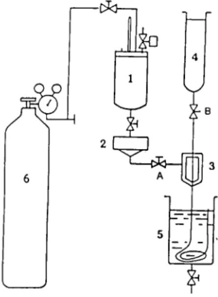
LBFig. 1. Schematic diagram of hollow-fibre spinning system.
2.2. Preparation o f hollow fibres
Hollow fibres were made by the wet-dry spinning process. The spinning system was the same as that described in detail in Liu et al. [ 11 ] except there was no hollow-fibre take-up. Instead, the hollow fibre dropped freely under the gravitational effect into a coagulation bath (Fig. 1). Therefore, the flow velocity
Table 1
Range of variation of parameters involved in hollow-fibre spinning
Parameter Range of variation
Temperature of spinning dope, T (°C) 25-60 Flow-rate of inner coagulant fluid, Qw (ml/s) 6.0-30.6
Air gap, h (cm) 60
S. Mok et al. / Journal of Membrane Science 100 (1995) 183-192 185
0 . 5 turn
0 . 2 m r n
- , ~ - - - 1 . 4 1 a m
Fig. 2. Spinneret nozzle geometry.
at 4°C. The volumetric flow-rate of the polymer solu- tion was kept constant at 0.032 cm3/s by adjusting the valve A and the extrusion pressure P. The geometry of the spinneret is given in Fig. 2.
Some remarks are in order on the definition of Qw, the volumetric flow-rate of internal coagulant deter- mined experimentally without a concurrent flow of pol- ymer solution (cm3/min), and u, the flow velocity of the internal coagulant with a concurrent flow of poly- mer solution ( c m / m i n ) . The flow velocity of polymer solution should also be equal to u when a steady state is reached. The velocity u was not determined experi- mentally, however, u is expected to increase with an increase in Qw.
2.3. Membrane surface modification
In order to improve the performance of hollow-fibre membranes, the internal skin layer of selected hollow fibres was treated with PEG polymers of various molec- ular weights. The hollow fibres were cut into the desired lengths immersed in water with nitrogen gas bubbled through it for 16 h. An aqueous solution of PEG in a syringe was deoxygenated by passing nitrogen gas through the solution. The deoxygenated polymer solu- tion was then injected into the bore side of the fibre with a syringe against a stream of nitrogen gas. The fibres were drawn into wet glass tubes sealed with rubber stoppers, placed in a gamma cell for the appro- priate times (0.5-2 h) and irradiated at a rate of 0.7
Mrad/h. After y-ray irradiation, the hollow fibres were flushed with distilled water to remove excess polymer solution.
2.4. Morphology studies
In order to study the effects of spinning condition on the morphology of the hollow fibre, selected samples of hollow fibres were prepared for SEM investigation. Cross-sections of hollow-fibre membranes were pre- pared for SEM by quenching in liquid nitrogen and breaking the fibres at liquid nitrogen temperatures with- out damaging the fibres. The sample was then attached to a carbon holder and shadowed with a thin gold layer to prevent charging up of the surface by the electron beam. A narrow beam of electrons with kinetic energies in the order of 1-25 kV hits the membrane sample, and low-energy electrons were liberated from the atoms in the surface to create the image on the micrograph.
2.5. Ultrafiltration experiments
Hollow fibres were tested in bundles of one to three fibres, each 28 cm long. The fibres were potted at both ends with epoxy resin and mounted in a test module. The operating pressure and feed flow-rate were 20 p.s.i.g, and 1 m/s, respectively. The feed solution was supplied to the bore side of the hollow fibre, and the permeate was collected from the shell side. The PEG solute concentration in the feed solution was kept at 200 ppm. The concentrations of the feed and permeate solutions were determined by using a Beckman Model 915B carbon analyzer. The solute separation, f, was calculated by the following equation:
f = Cfo~d - Cecm~at~ ( 1 )
Cfeed
The pure water permeation rate, PWP, and the product rate for each solute, PR, were also obtained.
3. Results and discussion
3.1. Effect of the spinning conditions on the fibre geometry
Table 2 shows the change of Ao, ratio of the outer radius (ro) to the inner radius (ri) of the hollow fibre,
186 S. Mok et al. / Journal of Membrane Science 100 (1995) 183-192
Table 2
Ratio of outer radius to inner radius, ho, of hollow fibres spun at different flow-rates of internal coagulant
Membrane type Qw (c m3/min) ho
R0.2-25 6.0 2.55
R0.2-25 30.6 1.28
R0.2-60 6.0 2.00
R0.2-60 30.6 1.25
Table 3
Change in dimension of hollow fibres spun from dopes at different temperatures
Membrane type Ao r~ (cm) Wall thickness (mm) R0.6-45 1.33 0.045 0,150
R0,6-35 1.35 0.050 0.175 R0.6-25 1.61 0.045 0,275
Table 4
Effect of PVP weight fraction in the dopes on dimensions of hollow fibres
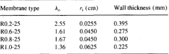
Membrane type ho r~ (cm) Wall thickness (mm) R0,2-25 2.55 0.0255 0.395
R0.6-25 1.61 0.0450 0.275 R0.8-25 1.67 0.0450 0.300 R 1.0-25 1.36 0.0625 0.225
with an increase in the flow-rate of the inner coagula- tion fluid, Qw. A code was given to each membrane according to the casting solution composition and cast- ing solution temperature. For example, the code R0.2- 25 means that the PVP/PES ratio in the casting solution was 0.2, and the casting solution temperature was 25°C. The same system of the membrane code will be used in Tables 2-5.
As discussed in the experimental section, the average flow velocity of the polymer solution, u, is supposed to increase with increasing Qw. Remember that the vol- umetric flow-rate of the polymer solution, V, was kept constant throughout the experiments. Then, Ao should decrease with increasing Qw, since the following equa- tion holds:
V= 7rff(Ao- 1)2u (2) The data in Table 2 meet the above expectation.
Table 3 shows that Ao and wall thickness increased with decreasing casting solution temperature. The
PVP/PES ratio was kept constant at 0.6 for this series of experiments. These results can also be easily explained by Eq. 2. Since the viscosity of the casting solution increases with decreasing temperature (see Appendix), u should decrease. Then, Ao increases to maintain V constant.
Finally, Table 4 shows that, at a constant casting solution temperature, the increase in PVP/PES ratio results in a decreases of Ao (--ro/ri). This, at a first glance, looks strange, since an increase in PVP/PES ratio also causes an increase of solution viscosity /x (see Appendix) and consequently a decrease of u. However, Table 4 shows also that the inner radius of the hollow fibre, ri, increases significantly with an increase in PVP/PES ratio. Examining closely ri val- ues, the latter is almost the same as the radius of the nozzle outlet for the internal coagulant (0.025 cm), when the PVP/PES ratio is 0.2. The ri value increases and becomes exactly the same as the inner radius of the casting solution nozzle at PVP/PES ratios of 0.6 and 0.8, and even larger at a PVP/PES ratio of 1.0. This indicates that the casting solution is drawn to the inter- nal coagulant stream of high velocity when the polymer solution viscosity is low. At higher viscosity this effect should be much less pronounced. At the highest PVP/ PES ratio of 1.0, ri was even greater than the inner radius of the polymer solution nozzle. Although the reason is not clear, the contraction of the polymer solu- tion volume as a result of the solvent-coagulant exchange may be one of the reasons.
Therefore, there are two opposing effects of increas- ing PVP/PES ratio on the Ao value. One is the effect of increasing viscosity, which decreases u and Ao according to Eq. 2. The other is the effect of increasing ri value, which results in a decrease in Ao according to Eq. 2. Obviously, the latter effect overcompensated the former effect when the PVP/PES ratio was increased.
3.2. Effects o f the composition o f the casting solution and its temperature on the ultrafiltration performance
The effect of the casting composition and the casting solution temperature on the ultrafiltration performance was investigated by measuring the separation of PEG solutes of various molecular weights and the permea- tion rate. The results are listed in Table 5. Some of the selected results are illustrated in Fig. 3. Since the con- centration of the PEG solute in the feed solution was
S. Mok et a l . / Journal of Membrane Science 100 (1995) 183-192
Table 5
Performance data of PES hollow-fibre membranes
187
Membrane type PWP (g/cm 2 h) PEG 1500 PEG 3000 PEG 6000 PEG 9000
Solute separation, f (%) R0.2-25 4.03 23.64 56.76 84.40 95.09 R0.2-35 7.87 43.23 73.41 88.23 95.43 R0.2-45 5.25 62.96 73.87 82.18 91.87 R0.2-60 7.53 44.10 69.50 84.18 88.51 R0.4-25 3.11 70.13 83.84 92.18 95.1 l R0.4-35 7.58 59.54 72.50 82.06 95.29 R0.4-45 7.41 31.85 60.21 79.16 92.99 R0.4-60 9.95 47.28 64.56 76.84 86.88 R0.6-25 4.06 52.37 74.92 87.14 92.53 R0.6-35 13.53 39.04 66.92 85.85 88.11 R0.6-45 20.43 21.95 47.28 67.92 80.70 R0.6-60 21.61 23.78 40.20 60.16 69.54 R0.8-25 7.08 29.59 63.67 80.76 87.65 R0.8-35 9.21 32.76 64.86 82.60 87.77 R0.8-60 5.39 30.71 44.45 75.15 87.38 R 1.0-25 15.58 25.09 43.34 66.91 86.14 R 1.0-45 17.77 21.79 37.57 66.50 87.51 R 1.0-60 19.13 24.33 42.06 66.27 87.51
small (200 p p m ) , the osmotic pressure effect was almost negligible. Therefore, the permeation rate with and without the presence o f the solute in the feed were practically equal. Therefore, only the pure water per- meation flux is reported in Table 5. Further, the velocity of the feed flow in the bore of the hollow fibre was 1 m / s . According to the evaluation o f the mass transfer coefficient in the previous work with hollow fibres whose geometry was similar to the present ones, the mass transfer coefficient corresponding to the above feed velocity is 5 . 6 . 1 0 " m / s for PEG 1500 solute. For this value o f the mass transfer coefficient and the permeation velocity of the solution, the concentration polarization effect is not necessarily negligible. Care must be taken, therefore, to interpret the experimental data.
When we look at the data at 25°C in Table 5, a m a x i m u m solute separation is found at a P V P / P E S ratio of 0.4, while an increasing tendency is observed in the pure water permeation flux with an increase in the P V P / P E S ratio. The decreasing tendency o f the solute separation observed at the high P V P / P E S ratios could be the result of concentration polarization. These results are in accordance with the work o f Lafreni~re et al. [ 13 ], in which they found that the flux showed a maximum when the P V P / P E S ratio was 1.0. Since their work was performed with flat membranes with a back-
~E
Ol 20 • ~5 to 5 0 26 Io0 ~e o m 80 ~ 70 ~ 60®
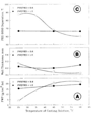
3 PVP/PES = 0.6 • pVP/PES : 1.0 0 PVP/PES = 0.6 " ~ 1 • PVP/PES = 1.0 0 ~ 3 - "2) L . . . PVP/PES = 0.6 O..~...0- :) fn ~ 25 30 35 40 45 5O ~,5 ~;o T e m p e r a t u r e o f C a s t i n g S o l u t i o n , ~ kFig. 3. Effect of temperature of casting solution on performance and geometry of hollow fibres spun with different weight ratios of addi- tive: (D) PVP/PES=0.6, ((3) PVP/PES= 1.0.
188 S. Mok et al. / Journal of Membrane Science 100 (1995) 183-192
Table 6
Comparison of performance of hollow fibres with various surface modification conditions
Membrane type a PWP ( g / c m 2 h) PEG 1500 PEG 3000 PEG 6000 PEG 9000
Solute separation,f ( % ) S-NC 6.04 71.26 90.08 97.75 98.72 S- 1 OK- 1 4.67 55.49 75.63 90.77 94.64 S-35K- 1/2 4.29 59.05 81.56 90.92 93.80 S-35K- 1 4.70 63.85 81.56 90.44 94.70 S-35K-2 5. ! 7 66.70 85.09 94.09 94.48 S- 100K- 1 6.75 69.72 86.57 95.59 96.20
aAll hollow fibres are prepared from PISS polymer (Vitrex 200P) solution (22 wt.-%) in dimethylacetamide solvent with a PVP/PES ratio of 0.4. The casting temperature was 25°(:.
ing support material and the present work with hollow- fibre membranes, the above agreement indicates that at least the effect of the PVP/PES ratio on the membrane performance is common for both flat-sheet and hollow- fibre membranes. They also concluded from the intrin- sic viscosity measurement that the interaction between the PVP and PES polymers is strongest when the PVP/ PES weight ratio is in the range 0.4-1.0. It should also be noted that the permeation rate of flat-sheet mem- branes in the work of Lafreni&e et al. [ 13] is in the same range as that of the hollow fibre membranes developed in the present work.
The effect of the casting solution temperature on the membrane performance is depicted in Fig. 3, where the separation of the PEG solute with a molecular weight of 6000 and the pure water permeation flux (PWP) are illustrated versus the casting solution temperature together with the hollow-fibre wall thickness. While solute separation, pure water permeation flux and wall thickness are practically constant with respect to a PVP/PES ratio of 1.0, solute separation decreases, pure water permeation flux increases and wall thickness decreases with increasing casting solution temperature
with respect to a PVP/PES ratio of 0.6. This data indi- cates that the effect of the casting solution temperature on the membrane geometry and the membrane per- formance is small when the PVP content in the casting solution is large, and consequently the viscosity of the casting solution is high.
It has been shown above that the pure water perme- ation flux is closely related to the wall thickness. This correlation, however, should not be overemphasized. It is known that the flux of the asymmetric membrane is governed by the thickness of the active surface layer and not by the total membrane thickness. The correla- tion between the pure water permeation flux and the total membrane thickness can only be expected when the thickness of the active surface layer increases when the total membrane thickness increases, or vice versa.
3.3. Effect of PEG grafting by y-ray irradiation
Tables 6--9 summarize the results of the experiments for hollow fibres whose inner surface was modified by grafting PEG by T-ray irradiation. The molecular weight of PEG, the duration of y-ray irradiation and
Table 7
Comparison of performance of hollow fibres with various surface modification conditions
Membrane type PWP ( g / c m 2 h) PEG 1500 PEG3000 PEG6000 PEG 9000
Solute separation, f (%) R0.2-35-NC 7.87 43.23 73.41 88.23 95.43 R0.2-35-10KI 1.98 24.68 57.60 83.38 94.62 R0.2-35-35KI/2 4.56 23.64 59.90 84.26 94.93 R0.2-35-35K 1 2.36 23.71 58.29 84.11 93.93 R0.2-35-35K2 0.28 22.34 52.74 83.47 86.11 R0.2-35 - 100K 1 3.87 38.28 67. i 3 85.95 94.66
S. Mok et al. / Journal of Membrane Science 100 (1995) 183-192
Table 8
Comparison of performance of hollow fibres with various surface modification conditions
189
Membrane type PWP (g / cm 2 h ) PEG 15OO PEG 3000 PEG6000 PEG 9000
Solute separation, f (%) R0.6-45-NC 20.43 21.95 47.28 67.92 80.72 R0.6-45-1 OK 1 24.05 14.87 30.74 54.33 72.42 R0.6-45-35K1/2 28.54 16.85 32.88 43.59 68,43 R0.6-45-35K 1 26.26 16.84 28.51 44.00 72.98 R0.6-45 -35 K2 19.52 l 6.50 27.93 46.18 76.38 R0,6-45 - 100K 1 17.96 25.84 47.30 63.26 83.24
the pore size of PES membranes before the surface treatment, which are called PES base membranes here- after, are the three variables involved in this work. Codes are given to each membrane listed in Tables 6 - 9. For example, R0.2-35-NC indicates that the base PES membrane is the same as R0.2-35 in Table 5 and the membrane was subjected to no surface modifica- tion. R0.2-35-10K-1 means that the base PES membrane is R0.2-35 and the inner surface of the hol- low-fibre membrane was treated with PEG of molecu- lar weight 10 000 and the duration of y-ray irradiation was 1 h. There are two base membranes that are not included in Table 5. Codes S and T are given to those base membranes for which the conditions of membrane preparation are given in detail in the footnotes of Tables 6-9.
With respect to the results of the first three groups of data including those for S, R0.2-35 and R0.6-45 base membranes (Tables 6 - 8 ) , the solute separation is either unchanged or lowered with the surface treatment. Only in the case of the R0.6-45 base membrane, a slight increase is observed when the membrane surface was modified with PEG of molecular weight 100 000 and the duration of y-ray irradiation was 1 h. Since the
solute separation of R0.6-45-NC is lower than those of S-NC and R0.2-35-NC base membranes, a more spec- tacular effect of the surface modification would be expected when the pore size of the base membrane would be even larger. A PES base hollow-fibre membrane was prepared, therefore, from a polymer solution without any PVP additive. It is known from the experiment with flat-sheet membranes that the pore size becomes larger (consequently solute separation becomes smaller) and flux becomes significantly lower when a membrane is cast from a casting solution with- out any PVP additive.
Referring to the data in Table 9, the same effect is observed with respect to hollow-fibre membranes, i.e. both separation and pure water permeation flux decrease significantly compared with membranes cast from the casting solutions including PVP. The data in Table 9 also show that the solute separation increases progressively with an increase of the molecular weight of the grafted PEG from 10 000 to 200 000 with some sacrifices in the pure water permeation flux. The con- centration polarization effect is negligible when the pure water permeation flux, PWP, is below 1 g / c m 2 h. Therefore, the results in Table 9 reflect the real effect
Table 9
Comparison of performance of hollow fibres with various surface modification conditions
Membrane type a PWP ( g / c m 2 h) PEG 15OO PEG 3000 PEG 6000 PEG 9000
Solute separation, f ( % ) T-NC 1.02 13.60 9.37 21.25 74.38 T- 1 OK- I 0.40 31.20 54.82 64.29 96.32 T-35K- 1 0.37 36.30 59.54 80.14 93.39 T- 100K- 1 0.63 40.63 59.36 82.61 96,80 T-200K- 1 0.62 54.90 74.90 86.60 96.94
a All hollow fibres are prepared from PES polymer (Vitrex 600P ) solution (25 wt.-% ) in NMP solvent without any PVP. The casting temperature was 25°C.
190 S. Mok et al. / Journal of Membrane Science 100 (1995) 183-192
- . ( c )
~ ' ; ' i " " .C, ,''< ' ~.~"': , S" . .I .~
• "'~"~'~2/"" ~ '" "¢ " ;'1
of PEG grafting. These data indicate that the pore size of the base membrane should be sufficiently large for the surface modification to be effective.
3.4. Electron micrographic observation
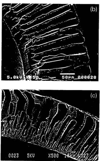
Fig. 4 shows the electron micrographic picture of the cross-sections of hollow-fibre membranes R0.2-45 (a), R0.4-45 (b) and R1.0-45 (c), respectively. Fig. 4a clearly indicates the presence of two dense layers both on the bore side and on the shell side of the hollow fibre, large finger-like voids being sandwiches in between. Finger-like macrovoids appeared even when PVP was added. The macrovoid may disappear when the molecular weight of PVP is higher than 10 000 [ 14]. It is also interesting to note that there is a bound- ary between the region of small finger-like voids and that of large finger-like voids near the shell side surface of the hollow fibre. This is considered to be the bound- ary where the flows of the gelation media by diffusion from the bore side and from the shell side meet. Fig. 4b and c indicate that more space is occupied by the finger-like voids and the front of the finger advances more towards the shell side surface when the PVP con- tent in the casting solution is higher. This can be attrib- uted to the hydrophilic nature of the PVP additive, which, at higher PVP/PES ratios, draws a larger amount of water into the polymer solution before it enters the gelation bath. Fig. 4c also shows that the inner dense layer is much thicker, which indicates that the gelation takes place as soon as the casting solution leaves the nozzle of the spinneret.
4. Conclusions
Fig. 4. Comparison of finger-like cavity structure of hollow fibres spun from casting solution with different weight ratios of additives at 45°C: (a) P V P / P E S = 0 . 2 , (b) P V P / P E S = 0 . 4 and (c) PVP/ PES = 1.0
From the above experimental results and theoretical considerations, the following conclusions can be drawn:
Under the condition of a constant flow-rate of the polymer solution and a constant inner radius of the hollow fibre:
1 ) The ratio (outer radius/inner radius) of the hollow fibre decreases with an increase in the flow-rate of the internal coagulant.
2) The above ratio decreases with an increase in the casting solution temperature.
S. Mok et al. / Journal of Membrane Science 100 (1995 ~ 183-192 191
3)
4)
5)
6)
Under the condition of a constant flow-rate of the polymer solution:
The above ratio decreases with an increase in the inner radius of the hollow fibre.
The above ratio decreases with an increase in the viscosity of the polymer solution, since the inner radius of the hollow fibre increases together with the solution viscosity.
As for the ultrafiltration performance of hollow- fibre membranes:
The separation of PEG solutes and the membrane flux are functions of PVP/PES ratio in the polymer solution and the polymer solution temperature. The separation of PEG solutes increases signifi- cantly by grafting PEG to the internal surface of the hollow fibre by ",/-ray irradiation. However, the
7)
separation of PEG 6000 by the base hollow fibre should be as low as 20% under the ultrafiltration conditions with an operating pressure of 20 p.s.i.g. and a feed concentration of 200 ppm for the graft- ing to be effective.
Since the hydrophilicity of the internal surface of hollow fibres is increased by PEG grafting, the hollow fibre becomes less susceptible to fouling by the adsorption of organic contaminants. There- fore, the surface-modified hollow fibres have great advantage in practical applications.
Electron micrographic pictures of the cross-section of the hollow fibre revealed that the proportion of the finger-like void space increases when a larger quantity of PVP is added to the polymer solution.
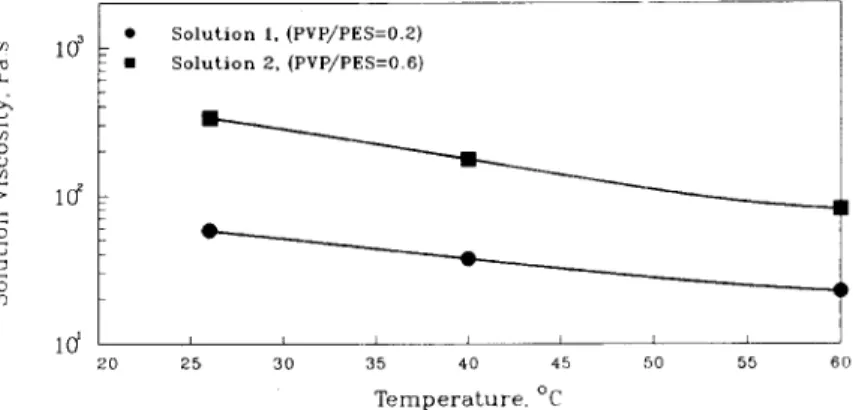
c~ ¢2 £ © o3 10 ~ • • S o l u t i o n S o l u t i o n 2 , ( P V P / P E S = 0 . 6 ) 1, ( P V P / P E S = 0 . 2 ) k k I ~ I J I I 2 0 2 5 3 0 35 40 45 50 Temperature, °C ! D t 5 5 6 0
Figure A.2 Effect of Temperature on Solution's Viscosity
c~ C.. c) r~ ; > © o3 lO2 ld S o l u t i o n s 1 , 2 , 3 , 4 a t t e m p e r a t u r e = 2 6 ° C 0",2 0 4 0 6 o.o R a t i o o f P V P / P E S
192 S. Mok e t aL / Journal o f Membrane Science 100 (1995) 183-192
Acknowledgements
References
T h e authors t h a n k Mr. Gerald Pleizier for p r o v i d i n g the S E M photographs a n d are grateful to Mr. S. D e n g and Ms. J. W a n g for c o n d u c t i n g the viscosity m e a s u r e - m e n t s in this work. T h e authors are also grateful for the support p r o v i d e d b y the N a t i o n a l Research Council.
Appendix 1
T a b l e A. 1 C o m p o s i t i o n o f P E S solutions S o l u t i o n P V P P E S N M P P V P / P E S No. (wt.- (wt.- ( w t . - % ) ratio%)
%)
1 4.4 22.0 73.6 0.2 2 13.2 22.0 64.8 0.6 3 17.6 22.0 60.4 0.8 4 22.0 22.0 56.0 1.0 T a b l e A.2Effect o f temperature a n d c o m p o s i t i o n o n the viscosity o f PES solutions Solution S o l u t i o n viscosity ( P s s) No. S o l u t i o n temperature 26°C 40°C 60°C 1 57.8 37.2 22.4 2 334.6 176.4 81.2 3 520.0 4 1266.0
[I] T.A. Orofino, in S. Sourirajan (Ed.), Reverse Osmosis and Synthetic Membranes, National Research Council Canada, Ottawa, 1977, p. 313.
[2] V.P. Caraccioio, N.W. Rosenblatt and V.J. Tomsic, in S. Sourirajan (Ed.), Reverse Osmosis and Synthetic Membranes, National Research Council Canada, Ottawa, 1977, p. 343. [3] F.S. Model, H.J. Davis and J.E. Poist, in S. Sourirajan (Ed.),
Reverse Osmosis and Synthetic Membranes, National Research Council Canada, Ottawa, 1977, p. 231.
[4] I. Cabasso, E. Klein and J.K. Smith, Polysulfone hollow fibres. I. Spinning and properties, J. Appl. Polym. Sci., 20 (1976) 2377.
[5] I. Cabasso, E. klein and J.K. Smith, Polysulfone hollow fibres. II. Morphology, J. Appl. Polym. Sci., 21 (1977) 165. [6] J.M.S. Henis and M.K. Tripodi, A novel approach to gas
separations using composite hollow fiber membranes, Sep. Sci. Technol., 15 (1980) 1059.
[7] M. Sidhoum, A. Sengupta and K.K. Sirkar, Asymmetric cellulose acetate hollow fibres: Studies in gas permeation, AIChE J., 34 (1988) 417.
[8] K. Nakagawa, Y. Kusuki and K. Ninomiya, Separation of water organic mixtures by vapor permeation through aromatic polyimide hollow fibres, in R. Bakish (Ed.), Proceedings of 4th International Conference on Pervaporation Processes in the Chemcial Industry, Bakish Materials Corp., Englewood, NJ, 1990.
[9] Y. Sakai and H. Tanzawa, Poly(methyl methacrylate) membranes, J. Appl. Polym. Sci., 22 (1978) 1805.
[ 10] I. Cabasso, Hollow fibre membrane research - - Morphology, pervaporation, gas separation and durability problems, in D. Lloyd (Ed.), Material Science of Synthetic Membranes, American Chemical Society, Washington, DC, 1985, p. 305. [ 11 ] T. Liu, S. Xu, D. Zhang, S. Sourirajan and T. Matsutu'a, Pore
size and pore size distribution on the surface of polyether sulfone hollow fibre membranes, Desalination, 85 (1991) 1. [ 12] T. Liu, D. Zhang, S. Xu and S. Sourirajan, Solution spun hollow
fibre polysulfone and polyether sulfone ultrafiltration membranes, Sep. Sci. Technol., 27 (1992) 167.
[ 131 L.Y. Lafreni~re and F.D. Talbot, Effect of polyvinylpyrrolidone additive on the performance of polyethersulfone ultrafiltration membranes, Ind. Eng. Chem. Res., 26 (1987) 2385.
[ 14] B.M. Boom, I. M. Wienk, Th. van den Boomgaard and C.A. Smolders, Microstructures in phase inversion membranes. Part 2. The role of a polymeric additive, J. Membrane Sci., 73 (1992) 277.