HAL Id: hal-01714866
https://hal.archives-ouvertes.fr/hal-01714866
Submitted on 23 Feb 2018
HAL is a multi-disciplinary open access
archive for the deposit and dissemination of
sci-entific research documents, whether they are
pub-lished or not. The documents may come from
teaching and research institutions in France or
abroad, or from public or private research centers.
L’archive ouverte pluridisciplinaire HAL, est
destinée au dépôt et à la diffusion de documents
scientifiques de niveau recherche, publiés ou non,
émanant des établissements d’enseignement et de
recherche français ou étrangers, des laboratoires
publics ou privés.
Lyapunov Global Stability for a Reactive Mobile Robot
Navigation in Presence of Obstacles
Ahmed Benzerrouk, Lounis Adouane, Philippe Martinet
To cite this version:
Ahmed Benzerrouk, Lounis Adouane, Philippe Martinet. Lyapunov Global Stability for a Reactive
Mobile Robot Navigation in Presence of Obstacles. ICRA’10 International Workshop on Robotics and
Intelligent Transportation System, RITS10, May 2010, Anchorage, United States. �hal-01714866�
Lyapunov Global Stability for a Reactive Mobile Robot Navigation in
Presence of Obstacles
Ahmed Benzerrouk, Lounis Adouane and Philippe Martinet
LASMEA, Blaise Pascal University
24, Avenue des Landais, 63177 Aubière, France.
Abstract— This paper deals with the navigation of a mobile robot in unknown environment. The robot has to reach a final target while avoiding obstacles. It is proposed to break the task complexity by dividing it into a set of basic tasks: Attraction to a target and obstacle avoidance. Each basic task is accomplished through the corresponding elementary controller. The activation of one controller for another is done according to the priority task. To ensure the overall stability of the control system, especially at the switch moments, properties of hybrid systems are used. Hybrid systems allow switching between continuous states in presence of discrete events. In this paper, it is proposed to act on the gain of the proposed control law. The aim is to ensure the convergence of a common Lyapunov function to all the controllers. This ensures the stability of the overall control. Simulation results confirm the theoretical study.
I. INTRODUCTION
The control of a mobile robot navigating in a cluttered environment is a fundamental problem and is receiving much attention in the robotics community. The purpose is mainly to ensure to the mobile robot a suitable and a safe navigation (avoiding a risk of collision, respecting its structural constraints, etc..)
Some of the literature considers that the robot control is entirely based on the methods of path planning while involving the total or partial knowledge of its environment: Voronoi diagrams and visibility graphs [1] or Artificial potential fields functions containing all the information on the target [2] and the robot environment are among these methods. Another community is interested by the ability of the robot to achieve the control laws according to its constraints (structural constraints, jerk-control, etc.). Even if cognitive methods of path planning and replanning [3], [4], can also be found here, more reactive methods (based on sensors information rather than a prior knowledge of the environment) are more common [5], [6] or [7]. The proposed work falls into the latter approach.
To ensure the robot’s ability to accomplish a reactive task, it is proposed to explore behavioral control architectures originally proposed by Brooks [8]. This kind of architecture of control breaks the complexity of the overall task by dividing it into several basic tasks. Each basic task is ac-complished with its corresponding controllers. There are two major principles of coordinating them: the action selection [8] and merging actions [9]. In the first, only one controller selected from the basic controllers is applied to the robot at every sample time. In the second case, the control applied
to the robot is a result of merging all or a part of available controllers in the control architecture.
We note that the action selection is more interesting. Indeed, one controller is applied to the mobile robot at a given time. It is then easier to examine individual stability of each controller. However, random switch from one controller to another (avoiding obstacles, follow a trajectory, reaching a target, etc.) may cause instability of the global control law, even if each individual controller is stable [10].
Stability proof of this kind of control architecture has been little explored in the literature: in [5], a merging action node is introduced to the control automaton in order to smoothly switch between the two controllers. The advantage of studying each controller alone is then lost, since we have also to study the merging action node. Controlling a mobile robot to follow a trajectory in presence of obstacles, based on the theorem of multiple Lyapunov functions [10] was established in [11]: A third secondary controller was then introduced to satisfy this theorem. However, this control architecture is not suitable for any cluttered environment.
Finding a common Lyapunov function to the basic systems forming a hybrid system is not a simple task [12]. In this paper, we propose to deal with this problem by ensuring overall stability of our control architecture with a single Lyapunov function. Here we are interested by a mobile robot reaching a target while avoiding obstacles: this task is then divided into two basic tasks: attraction to a target and obstacle avoidance.
The rest of the paper is organized as follows: in next section, the basic controllers and the proposed control law are introduced. The proposed control architecture is exposed in Section III. Simulation results are given in IV. Finally, we conclude and give some prospects in Section V.
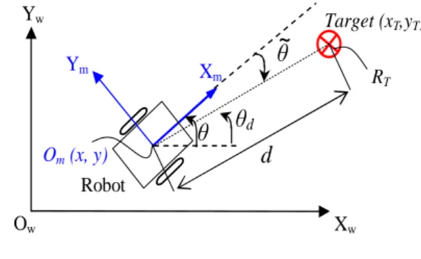
II. ROBOT MODEL AND TASKS TO ACHIEVE Before introducing attraction to the target controller, ob-stacle avoidance and the proposed control law, we recall that the kinematic model of the used unicycle mobile robot used is expressed by the well-known equations:
˙ x = vcos(θ) ˙ y = vsin(θ) ˙ θ = ω (1) With
Target (xT,yT) Robot
~
θ
Ym X md
RT Om (x, y)θ
dθ
Yw Ow XwFig. 1. Controller for attraction to target.
• (x, y) are the world coordinates of the robot axle center
Om (cf. Figure 1).
• θ is the world robot orientation.
• v and ω are respectively linear and angular velocities. A. Attraction to target controller
The robot has to reach a given target of radius RT and
coordinates center (xT, yT) (cf. Figure 1).
Position errors are defined as
ex = xT − x = d cos(˜θ)
ey = yT − y = d sin(˜θ)
(2) d is the distance of the robot to the target and can then be expressed as d = √ e2 x+ e2y (3) ˜
θ is the orientation error, such that : ˜θ∈] − π, π] is
˜
θ = tan−1(yc− y
xc− x
)− θ (4)
Its derivativeθ is then˙˜
˙˜ θ =(e˙y ex )/(1 + (ey ex )2)− ω (5)
After computation using the kinematic model (cf. Equation 1) and equations in (2) we obtain
˙˜ θ = ωr− ω (6) Where ωr= v sin(˜θ) d B. Obstacle avoidance controller
The objective of this controller is to control the robot to avoid obstacles that hinder its attraction to the target. To focus on the proposed control architecture, this controller is briefly described. The theoretical details are available in [13]. This controller is based on the limit cycle methods [14], [15]. The differential equations representing the desired trajectory of the robot are given by the following system
˙
xr= ayr+ xr(R2c− x2r− y2r)
˙
yr=−axr+ xr(R2c− x2r− y2r)
(7) With a =±1 according to the optimal direction of avoid-ance (clockwise or counterclockwise direction). (xr, yr) are
the relative robot coordinates with respect to the obstacle. The latter is characterized by a circle of radius Rcl =
Ro+ Rr+ ϵ where: Ro is the obstacle radius, Rr is the
robot radius and ϵ is a safety margin (cf. Figure 2). The algorithm for obstacle avoidance is summarized in the following
• The nearest hindering obstacle is detected.
• The direction of avoidance is chosen according to the sensor information.
• The robot avoids the obstacle while following a limit cycle which has a radius Rc= Rcl−ξ (attraction phase). • The robot avoids the obstacle while following a limit cycle which has a radius Rc = Rcl+ξ (repulsive phase)
(cf. Figure 2). Where ξ is a small value and (ξ≪ ϵ).
Obstaclei Target Robot O Y XO (1) Clockwise Attraction (2) Conter-Clockwise Attraction (3) Conter-Clockwise Repulsion (4) Clockwise Repulsion Rr Rcl Ro Ow Xw Yw
Fig. 2. Obstacle avoidance controller.
C. The proposed control law
It is interesting to notice that only one control law is applied to the robot even if its architecture of control contains two different controllers (attraction to the target and obstacle avoidance). Only the set points change according to the applied controller.
The proposed control law is expressed as follows: v = vmax e− 1 dcos(˜θ) (a) ω = ωr+ k1θ˜ (b) (8) where
• vmax is the maximum linear velocity. • k1 is a constant such that k1> 0.
• d is the distance robot-target (cf. Equation 3). The robot
reaches the target when 0 < d≤ RT (cf. Section II-A).
To study the stability of the proposed control law, consider the Lyapunov function
V = 1
2 ˜
θ2
The control law is asymptotically stable if ˙V < 0.
˙ V = ˜θθ˙˜ By replacing (6) in (8.b), we get ˙˜ θ = −k1θ˜ (9) and ˙V becomes
˙
V =−k1θ˜2< 0 (10)
and ˙V becomes for every ˜θ̸= 0.
The controller is then asymptotically stable.
Once each basic task and the control law are defined, the proposed architecture of control which coordinates them is given in next section.
III. THE PROPOSED ARCHITECTURE OF CONTROL Even if each controller is individually stable, it is impor-tant to constrain switch between them to avoid instability of the overall system, see [10]. Here, it is proposed to generalize the Lyapunov function previously defined (cf. Section II-C) for the overall control system. Indeed, it was proved (cf. Section II-C) that this function is strictly decreasing. However, the problem arises (as for all hybrid systems) at switching moments where the set point is discontinuous. This means that there is an unavoidable jump of the error ˜
θ at these moments. This naturally leads to jumps in the
Lyapunov function after the switch and this jump may lead to increasing it.
Hence, It is proposed to adjust the gain k1 of the control
law (cf. Equation 8) at the switch moments so that even if the value of the Lyapunov function increases during the switch, it returns to its value before switch V (tbs) in a finite time
Tmax. (tbs is the moment just before switch).
In addition, the robot should not navigate more than a dis-tance dmaxwhen (V (t) > V (tbs)) in order to insure stability
criterion as soon as possible. Also, when the robot performs the obstacle avoidance task, it is necessary that (dmax< ϵ)
(cf. Section II-B) to avoid collision with the obstacle. Notice that ϵ is the minimal distance separating the robot from the obstacle once this one is detected (cf. Section II-B).
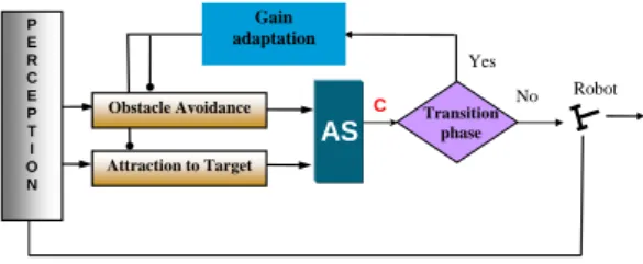
Attraction to Target Obstacle Avoidance P E R C E P T I O N C AS Gain adaptation Yes No Robot Transition phase
Fig. 3. The proposed architecture of control.
A. Adaptating the control law gain
The adjustment of the gain k1(cf. Equation 8) is triggered
if one of the following events occurs
• The control of the robot switches from one controller to another.
• Obstacle avoidance controller switches from an obstacle to another.
• Obstacle avoidance moves from attraction phase to repulsive phase (cf. Figure 2).
To insure that V decreases in a finite time Tmax that we
can impose, we have to get
V (ts+ Tmax) ≤ V (tbs) (11)
Where ts is the switch moment.
The resolution of the differential equation (9) gives the orientation error with respect to time ˜θ
˜
θ(t) = ˜θ(ts)e−k1(t−ts) (12)
Equation (12) allows to easily deduce the Lyapunov func-tion : ˜ θ2(t) = θ˜2(t s)e−2k1(t−ts) (a) V (t) = θ˜2(ts) 2 e−2k1 (t−ts) (b) V (t) = V (ts)e−2k1(t−ts) (c) (13) Thus, k1 is expressed as k1= ln(V (t)/V (ts)) −2(t − ts) (14) Note that k1 is always positive. Indeed, V (t)≤ V (ts) (cf.
Equation 13) and then ln(V (tV (t) s))≤ 0.
The value of k1 allowing to reach V (tbs) in a finite time
Tmaxis
k1=
ln(V (tbs)/V (ts))
−2Tmax
(15) Note that the restriction on Tmaxis necessary especially in
the case of obstacle avoidance. Indeed, the stability criterion of hybrid systems (cf. Equation 11) must be satisfied in minimal time. Moreover, the distance achieved during Tmax
has to be (dmax ≤ ϵ) (cf. Section II-B) to avoid collision
with the obstacle. It is easy to see that the minimum necessary time to achieve this distance is
tmin=
ϵ vmax
corresponding to a straight robot navigation to the obstacle center with its maximum linear velocity. (15) becomes then
k1=
ln(V (tbs)/V (ts))
−2tmin
(16) Note that k1 is not defined if V (tbs) = 0. The notion of
weak stability [16] allows to define a threshold Vmin such
that if V (t) < Vmin, then the system is (weakly) stable
without comparing V (t) to V (tbs). It means that
k1=
ln(Vmin/V (ts))
−2tmin
(17) Thus, k1is recalculated in this way and replaced in (8.b).
We can then summarize the proposed control architecture as in figure (Fig. 3).
B. The mechanism of the architecture of control
The block AS (for Action Selection) selects the suitable controller to apply to the robot according to the environment: if no obstacle is detected, Attraction to the target task is accomplished. If there is a discrete event (switching from one controller to another, transition from attraction to repulsive phase, etc.), the block transition phase prevents the control from affecting the robot’s actuators, until the block
0 10 20 30 40 50 60 70 0 0.5 1 1.5 2 Gain k1 constant 0 100 200 300 400 500 600 700 0 0.2 0.4 0.6 0.8 1 0 10 20 30 40 50 60 70 0 0.5 1 1.5
Lyapunov function variation
Switching control indicator: 0: Attraction to target, 1: Obstacle avoidance
Time [s]
Tmax1 Tmax2
Fig. 4. Variation of the Lyapunov function keeping k1constant.
0 5 10 15 20 25 15 16 17 18 19 20 21 22 23 24 25 1 2
Robot trajectory in the [O, X, Y] reference
X [m] Y [ m ] Final target Obstacle + Circle of influence
Fig. 5. Robot trajectory in presence of obstacles. IV. SIMULATIONRESULTS
To estimate the relevance of the proposed control archi-tecture, it is proposed to simulate a mobile robot navigation to reach a target in presence of obstacles. Simulation is made twice. In the first case, the used control law has a constant gain during all the navigation (k1= 1) (there is no
gain adjustment in the switch moments). Switching control indicating the active controller can be seen in figure (Fig. 4). In the second case, the proposed control architecture is implemented on the robot. In the two cases, the robot reaches its target while avoiding obstacles. However, by comparing Tmax1, Tmax2 which are convergence times for
obstacle avoidance controller in figures (Fig. 4 ) and (Fig. 6), it is noticed that the Lyapunov function of the proposed architecture of control converges faster than the architecture with a constant gain. Evolution of the gain k1 is given in
the same figure (Fig. 6). Note that attraction to the target controller converges fastly in the two cases even if in the proposed architecture, we can see that it is slightly faster.
V. CONCLUSION
A control architecture based on hybrid systems has been proposed. With these systems, it is possible to divide the control architecture into a set of elementary controllers to examine each controller separately. Even if each individual controller is stable, global stability is not necessarily guaran-teed. In this paper, the overall stability was established thanks to a single Lyapunov function. The proposed idea is to adjust the gain of the control law in order to accelerate convergence of the Common Lyapunov Function CLF after each switch. The simulation results have confirmed the theoretical study. In future works, it is proposed to introduce the gain k1 as a
0 10 20 30 40 50 60 70 1 1.5 2 2.5 3 3.5
Variation of the gain k1
0 10 20 30 40 50 60 70 0 0.2 0.4 0.6 0.8 1 Time [s] 0 10 20 30 40 50 60 70 0 0.5 1 1.5
Lyapunov function variation
Switching control indicator: 0: Attraction to target, 1: Obstacle avoidance
Tmax1 Tmax2
Fig. 6. Variation of the Lyapunov function and the gain k1 with the proposed architecture of control.
dynamical gain. Thus, once the lyapunov function converges, it returns to its nominal value without disturbing the control.
REFERENCES
[1] J-C. Latombe. Robot Motion Planning. Kluwer Academic Publishers, 1991.
[2] E. Rimon and D. E. Koditschek. Exact robot navigation using artificial potential fields. IEEE Transactions on Robotics and Automation, 8(5):501–518, 1992.
[3] C. Belta, V. Isler, and G.J Pappas. Discrete abstractions for robot motion planning and control in polygonal environments. IEEE Transactions on Robotics, 21(5):864–874, 2005.
[4] D.C. Conner, H. Choset, and A. Rizzi. Integrated planning and control for convex-bodied nonholonomic systems using local feedback control policies. In Proceedings of Robotics: Science and Systems, pages 57– 64, Philadelphia, USA, 2006.
[5] M. Egerstedt, K. H. Johansson, J. Lygeros, and S. Sastry. Behavior based robotics using regularized hybrid automata. Computer Science ISSN 0302-9743, 1790:103–116, 2000.
[6] J.M. Toibero, R. Carelli, and Kuchen B. Switching control of mobile robot for autonomous navigation in unkown environments. IEEE International Conference on Robotics and Automation, pages 1974– 1979, 2007.
[7] L. Adouane. Hybrid and safe control architecture for mobile robot navigation. In 9th Conference on Autonomous Robot Systems and Competitions, Portugal, May 2009.
[8] R. A. Brooks. A robust layered control system for a mobile robot. IEEE Journal of Robotics and Automation, 2:14–23, 1986.
[9] R. C. Arkin. Motor schema-based mobile robot navigation. Interna-tional journal of robotics research, 8(4):92–112, 1989.
[10] M. S. Branicky. Stability of switched and hybrid systems. In 33rd IEEE Conference on Decision Control, pages 3498–3503, 1993. [11] A. Benzerrouk, L. Adouane, P. Martinet, and Andreff N. Multi
lyapunov function theorem applied to a mobile robot tracking a trajectory in presence of obstacles. In European Conference on Mobile Robots, 2009.
[12] D. Liberzon. Switching in systems and control. Birkhäuser, 2003. [13] L. Adouane. Orbital obstacle avoidance algorithm for reliable and
on-line mobile robot navigation. In 9th Conference on Autonomous Robot Systems and Competitions, May 2009.
[14] D. Kim and J. Kim. A real-time limit-cycle navigation method for fast mobile robots and its application to robot soccer. Robotics and Autonomous Systems, 42:17–30, 2003.
[15] M.S. Jie, J.H. Baek, Y.S. Hong, and K. Lee Woong. Real time obstacle avoidance for mobile robot using limit-cycle and vector field method. Knowledge-Based Intelligent Information and Engineering Systems, pages 866–873, October 2006.
[16] B. Brogliato, S. Niculescu, and Orhant. On the control of finite dimensional mechanical systems with unilateral constraints. IEEE Transactions on Automatic Control, 42(2):200–215, 1997.