HAL Id: hal-01300701
https://hal.archives-ouvertes.fr/hal-01300701
Submitted on 11 Apr 2016
HAL is a multi-disciplinary open access
archive for the deposit and dissemination of
sci-entific research documents, whether they are
pub-lished or not. The documents may come from
teaching and research institutions in France or
abroad, or from public or private research centers.
L’archive ouverte pluridisciplinaire HAL, est
destinée au dépôt et à la diffusion de documents
scientifiques de niveau recherche, publiés ou non,
émanant des établissements d’enseignement et de
recherche français ou étrangers, des laboratoires
publics ou privés.
To cite this version:
Jean-Marie Jehanno, Antoine Cully, Christophe Grand, Jean-Baptiste Mouret. Design of a
Wheel-Legged Hexapod Robot for Creative Adaptation. CLAWAR 17th International Conference on
Climb-ing and WalkClimb-ing Robots, Jul 2014, Poznan, Poland. pp.267-276. �hal-01300701�
Design of a Wheel-Legged Hexapod Robot for Creative Adaptation
J.-M. JEHANNO, A. CULLY, C. GRAND and J.-B. MOURET
Sorbonne Universit´es, UPMC Univ Paris 06, UMR 722, ISIR, F-75005, Paris, France CNRS, UMR 7222, ISIR, F-75005, Paris, France
mouret at isir.upmc.fr
Thanks to recent advances in adaptation algorithms, it is now possible to give robots the ability to discover by trial-and-error the best way to behave in unexpected situations, instead of relying on contingency plans. In this paper, we describe the kinematic and mechatronic design of the Creadapt robot, a new mobile robot designed to take full advantage of these recent adaptation algorithms. This robot is a versatile wheel-legged hexapod designed for both legged and wheeled locomotion. It is reversible to be able to continue its mission if it flips over and it uses 6 legs to be able to move efficiently if one or several legs break. This robot also embeds two RGB-D cameras to estimate its velocity onboard, thanks to a RGB-D visual odometry algorithm. Overall, the Creadapt robot is one of the first mobile robot designed with adaptation algorithms in mind.
Keywords: wheel-legged robot; mechatronic design; hexapod; adaptation
1. Introduction
Autonomous robots are inherently complex machines that have to cope with dynamic and often adverse conditions, may they be on a remote planet, in a city, or even in a house. As a consequence, they have to be capable of recovering from unexpected damages and deal with unforeseen situations.1
Robustness and fault tolerance are classic research topics in robotics and engineering. The classic approaches rely on a combination of contingency plans, redundancy of components, and diagnostic of the faulty subsystems.2
However, they require extensive self-monitoring abilities and are costly to operate because of the redundancy.
In the Creadapt projecta
, we investigate an alternative approach: in-stead of trying to anticipate faults, we endow our robots with learning
a
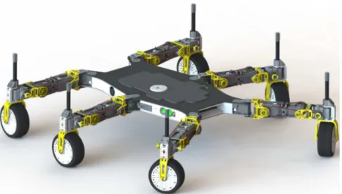
Figure 1. Overview of the Creadapt robot (3D rendering).
abilities that allow them to discover by trial-and-error the best way to be-have in the current situation. Following this line of thought, we recently introduced the T-Resilience algorithm, which allowed a hexapod robot to learn to walk again in less than 20 minutes after the loss of a leg removal, a broken leg or a motor failure. Nevertheless, the learning algorithm is only half of the story because, however good the algorithm, such a robot needs to possess the physical capabilities to achieve its mission in alternative ways. For instance, if a car breaks its engine, no learning algorithm will make it discover a new way to move.
In the present paper, we describe our attempt at designing a mobile robot that can move in many different ways so that the T-Resilience algo-rithm can be used at its full potential (Fig. 1). We designed our robot with legs because it is a versatile locomotion mode, especially in rough terrains. We used six legs, so that if one or several legs break, the robot can still find efficient gaits. On simple terrains, wheeled locomotion is often more efficient than walking. We therefore extended each leg by a powered, steer-able wheel, so that the robot can rely on classic wheeled locomotion when possible. This architecture also enables hybrid locomotion modes, depend-ing on how the wheels and the legs are coordinated. In addition, one of the classic issue with legged robots is their tendency to flip over and not being able to recover. We cannot pre-program a recovery procedure because we do not know whether the robot is broken, how it could be broken, or the
features of the terrain. We therefore equipped our robot with special legs that allows it to walk on its back. Last, we gave the robot two embedded RGB-D sensors and a visual odometry algorithm3
so that it can estimate its velocity on-board.
2. Background and Context
A hybrid locomotion system is defined as a mechanical system that com-bines various types of propulsion devices such as wheels, legs, or tracks, and that can handle specific locomotion modes like the roller-walking4
or the crawling modes.5
There are numerous ways to combine the propulsion devices, considering parallels6
or serials7
arrangements, or by using me-chanical reconfiguration of a subsystem, like a wheel that transforms to a foot.4
Some systems are based on multiple propulsion devices, like the Azimut robot, which uses wheels, legs and tracks.8
In this project, our developments are focused on the wheel-legged hy-brid architecture that use wheels mounted at the end of actuated legs. Many robots have already been developed based on this mechanical architecture. Most of them are based on a 4 wheel-legs arrangement such as the Hylos robot,9
the Workpartner,10
the RIMRES-Sherpa11
or the PAW robot.12
A minimalist version, the family of robots Tri-Star, uses only three wheels and is dedicated to planetary exploration.13
An interesting variant is im-plemented in Chimp, from CMUb
, which uses tracked locomotion devices at the end of its four limbs. This robot was recently demonstrated during the DARPA Robotics Challenge.
Wheel-legged robots with three or four limbs are interesting structures because they can adapt their posture to the terrain and optimize some per-formance criteria like their tip-over stability. However, they easily become sub-efficient if they are damaged, for example when a motor fails or when a mechanical part breaks. The use of more than four legs offers more ver-satility and extends the behavioral diversity, allowing the system to learn new locomotion modes when needed. To our knowledge, Athlete, developed by NASS/JPL,14
and Asterisk-H, from the Arai Laboratory,15
are the only wheel-legged robots with more than four legs.
In the following section, we describe the path that we followed to develop our 6-wheel-legged robot.
b
3. Kinematics A1 A2 A3 A4 A5 A1 A2 A3 A4 & P3 A5 P3 P2 P1 P2 P1
Figure 2. Kinematic design of the legs. A1, A2, A3, and A5 are actuated. The wheel is also actuated. A system of pulleys (P1, P2, and P3) drives the degree of freedom A4, so that the wheel is always perpendicular to the body. The foot is not mounted on this prototype.
The Creadapt robot has a semi-hexagonal body shape with six identical legs (Fig. 1). Each leg has in total 6 degrees of freedom (DOF): 4 actuated DOFs, 1 underactuated DOF, and 1 actuated wheel.
The kinematics of each leg (Fig. 2) is divided into two parts: (1) a classic 3-DOFs leg kinematics, with a first vertical joint (Fig.2: A1), which controls the orientation of the leg, and two horizontal joints (Fig.2: A2 and A3), which control its elevation and extension; and (2) a steerable, actuated wheel (Fig.2: A5 and the wheel). All these degrees of freedom and the wheel are actuated.
The normal direction of the contact surface between the wheel and the ground directly impacts the friction and thus the thrust produced by the wheel. For this reason, the two kinematics parts are coupled with an un-deractuacted joint (Fig.2: A4) that keeps the wheel perpendicular to the robot’s body. The alignment is obtained thanks to a cables and pulleys system that copies the orientation of the body. This system includes a combination of three serial pulleys. The first pulley (Fig.2: P1) is fixed to the first segment (between A1 and A2) which has the same angular orien-tation than the body. The second pulley (Fig.2: P2) is free. The third one is fixed to the pivot joint axis (Fig.2: A4). Two cables transmit the movement from the first pulley to the second, and from the second to the last one. As
a consequence, the first and the final pulley always have the same angular position, whatever the position of intermediate segments.
If the robot flips over, this system will prevent the robot to flip the wheel segment. To cope with this issue, we append a foot to the top of each leg so that the robot can continue its mission by walking on its back. Thanks to the cable system, the the feet will still be perpendicular to the body. The position of the tip of the foot (the contact point) is symmetrical to the wheel. 4. Design Trade-offs AX-12/MX-28 MX-28/MX-28 MX-28/MX-64 MX-64/MX-106 MX-106/MX-106 To ot he d be lt re du ct io n ra tio
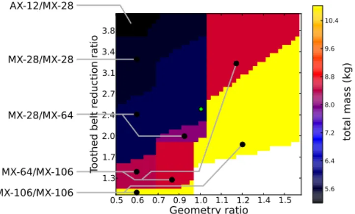
Figure 3. Results of the preliminary design algorithm. Valid servomotors combinations are sorted according to the their toothed belt reduction ratio, geometric ratio, and their weight. White area indicates that no valid candidates are available. The green point is the selected combination (reduction of 2.5 and a geometry ratio of 1). Each colored zone corresponds to a particular combination of servo-motor for the A2 and A3 DOF; servo-motors for A1 and A5 are not displayed on this figure but their are present in the output of the algorithm. For instance, AX-12/MX-28 means that this zone corresponds to an AX-12 servo-motor for A2 and a MX-28 for A3. The Dynamixel AX/MX range contains the following servo-motors, from the lightest (smallest torque) to the heaviest (largest torque): AX-12, MX-28, MX-64, MX-106.
To explore the design trade-offs, we designed a preliminary design al-gorithm that searches for the best servo-motors and battery combinations for all the actuated joints. The algorithm takes as input a set of parame-ters that constrain the design: body shape (semi-hexogonal, width equals to length of A2 to A3), minimum and maximum limbs length, autonomy (here fixed to 30 minutes), maximum slope angle for wheeled locomotion
(10 degrees), and maximum weight (9kg). To increase the range of pos-sible torques, we included the possibility to connect the servo-motors to the axis via a pulley/toothed belt system, whose reduction ratio has to be determined by the algorithm. We here call geometry ratio the length of the segment A2-A3 divided by 122mm (that is, the length of two MX-64 actuators). The width of the body is the same as A2-A3, and the length A3-A4 is equal to 0.8 times the length of A2-A3, as suggested by Kanner and Dollar.16
The algorithm enumerates all the possible combinations of bat-tery/actuators of each DOF/reduction ratio/geometry ratio by picking ser-vomotors in the Dynamixel servo-motor catalog and batteries in the Pro-tronics LiPo battery catalog. After the enumeration, it selects the candi-dates that can roll, walk, lift their own legs, get up with only two legs, and whose battery can supply the nominal and peak current required by the motors. These criteria are evaluated with a static computational model. Among valid candidates (if any), we pick the lightest one.
This preliminary design algorithm outputs a 2-dimensional design space (Fig.3), where solutions are plotted according to their geometry ratio, which characterizes the size of the robot (including the size of the legs), with regard to the toothed belt reduction ratio for the DOFs A2 and A3, and the total weight.
The resulting combinations range from light and weak to heavy and powerful solutions (Fig.3). Higher toothed belt ratio allow the robot to use weaker and thus lighter servomotors (i.e. AX-12); higher geometry ratio implies to deal with higher torques and thus require stronger but heavier servo-motors (i.e. MX-106).
We selected the final combination (Fig.3) by searching for the lightest and the largest robot while taking into account three points: (1) many reduction ratios cannot be produced with standard gears and standard toothed belt; (2) a high reduction ratio implies a reduction of the range of movement (servomotors typically have a range of 300 degrees, which is divided by the toothed belt reduction ratio); (3) the feasibility of geometry ratios lower than 1 depends on the combination of actuators.
Table 1. Main characteristics of the Creadapt robot.
total weight 7 kg
body dimension 580mm x 350mm overall dimensions 580mm x 350mm; single leg payload 3kg
wheeled locomotion speed 0.25 m/s walking speed 0.30 m/s
Actuators A1:MX-64; A2: MX-28; A3: MX64; A5: AX12
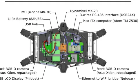
Li-Po Battery (8Ah/3S) IMU (X-sens Mti-30)
USB hub
3-wires RS-485 interface (USB2AX) Pico-ITX computer (Atom TM Z530)
Ethernet to WIFI bridge (Netgear) Front RGB-D camera (Asus Xtion, repackaged) Back RGB-D camera
(Asus Xtion, repackaged) USB LCD Display (Phidget)
Dynamixel MX-28
Figure 4. Main components of the body: sensors, battery, computer.
5. Mechatronics
All the actuated degrees of freedom are powered by position driven servo-motors from the Dynamixel product rangec
. These servos offer integrated PID position control and use a communication bus (3-wires RS-485) to communicate with each of the 30 motors.
The first leg segment incorporates two servomotors that actuate axes A2 and A3 (Fig.2). The final design of the toothed belt reduction is made by inverting the position of the 2 servomotors of the second segment (the servomotor nearest to A2 actuate A1, and reciprocally). The belts (in red on Fig.2, right) actuates an axis that is coaxial to the output of the opposite servomotor. This solution embeds the two servomotors and the reduction system in a single and compact leg segment, and thus reduces the inertia of the terminal segment.
c
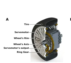
Tire Wheel's Rim Servomotor Wheel's Axis Servomotor's output Ring Gear A B
Figure 5. (A)Cross section of the wheel. (B) The wheel mounted on the leg.
The wheel hub embeds a Dynamixel AX12-W servomotor that actuates the wheel (see Fig.5). We rewrote the firmware of the AX12-W to implement a PID speed control, instead of the original position control. This solution takes advantage of the servomotor compactness to undertake a compact and inertia-centered wheel design. The output of the servomotor is reduced by gears to increase its torque and the final ring gear is fixed to the wheel’s rim that makes the wheel rolling. Wires to power and control the motor go through the axis of the wheel. Tires come from radio-controlled cars.
During the learning experiments, the Creadapt robot has to optimize its velocity, which has to be evaluated onboard. For this purpose, our hexapod embeds two RGB-D cameras (Asus Xtion) to estimate the traveled distance with a recent, fast 3D visual odometry algorithm.3
In our preliminary tests, we obtained an accuracy of 5-10% when the robot is walking indoor. The two cameras are located in the front and the back of the robot to maximize their field of view and to ensure that one camera is always pointing forward. Having two cameras also allows the robot to cope with a broken camera.
The robot includes an inertial measurement unit (IMU Xsens MTI-30) to assess the orientation of its body, so that the robot can search for a control policy that minimize the oscillations. In addition, this information helps distinguishing whether the robot is on its wheels (normal operation) or on its feet (if the robot flipped over).
The sensors are connected to an embedded computer (pico-ITX format, Intel Atom Z530 processor – a hyper-threaded mono-core at 1.6 GHz with an x86 architecture), with 2 Gb of RAM. An LCD display and an input-ouput board with several switches and LEDS are on a side of the robot (Phidget USB LCD), to show the robot status and to select the operation
modes. All these devices are connected to the computer through an USB hub. An ethernet-wifi bridge is used to connect the robot to a wifi network, so that we can remotely operate the robot and send some computations to an external computer, if needed.
The computer runs Ubuntu and the ROS meta-operating system.17
A single, custom node takes care of the interactions with the servo-motors; a node is connected to each RGB-D sensor, which is itself connected to the visual odometry algorithm;3
a node interfaces the IMU; a last node interfaces the USB display.
All the devices of the robot are powered by a lithium-polymer battery (4S, 14.8V / 8000 mAh) that provides an autonomy of about 30 minutes, which is enough to evaluate the adaptation algorithm used in this project.1
The servomotors are directly connected to the battery, but the electronics devices are powered by an custom-made 5V DC-DC converter board. For longer experiments, the robot can be powered with an external power sup-ply. In such configurations, an ethernet cable is directly connected to the robot to avoid WIFI reception issues and improve the bandwidth.
6. Conclusion
The Creadapt robot blends off-the-shelf components, like Dynamixel ac-tuators, with specific systems, like the cable systems that passively keeps the wheel vertical, or the powered wheel with an integrated actuators and a custom firmware. The preliminary design algorithm allowed us to ex-ploit a computational model to rigorously select the best combination of components. Metal and plastic 3D-printing proved to be invaluable to use off-the-shelf components in original ways. The mechatronics design takes advantage the ROS meta-operating system to easily make a modern, mod-ular software platform. Overall, the design of the Creadapt robot illustrates how machine learning algorithms can influence mechatronics choices; it thus questions the classic design process in which mechanical design precludes control and adaptation algorithms.
All the CAD files and the developed software will be freely available on the website of the project (http://www.creadapt.net).
Acknowledgments
This work has been funded by the “Agence Nationale de la Recherche” (Creadapt project, ANR-12-JS03-0009) and a DGA/UPMC scholarship for A.C.
Bibliography
1. S. Koos, A. Cully and J.-B. Mouret, The International Journal of Robotics Research 32, 1700 (2013).
2. I. Koren and C. M. Krishna, Fault-tolerant systems (Morgan Kaufmann, 2007).
3. I. Dryanovski, R. G. Valenti and J. Xiao, Fast visual odometry and mapping from rgb-d data, in Proc. of IEEE Int. Conf. on Robotics and Automation (ICRA), 2013.
4. S. Hirose and H. Takeuchi, Study on roller-walk (basic characteristics and its control), in Proc. of IEEE Int. Conf. on Robotics and Automation (ICRA), 1996.
5. G. Besseron, C. Grand, F. Amar, F. Plumet and P. Bidaud, Locomotion modes of an hybrid wheel-legged robot, in Proc. of the 8th International Conference on Climbing and Walking Robots (CLAWAR), (Springer, 2005). 6. Y.-J. Dai, E. Nakano, T. Takahashi and H. Ookubo, Motion control of leg-wheel robot for an unexplored outdoor environment, in Proc. of IEEE/RSJ Int. Conf. on Intelligent Robots and Systems (IROS), 1996.
7. H. Adachi, N. Koyachi, T. Arai, A. Shimiza and Y. Nogami, Mechanism and control of a leg-wheel hybrid mobile robot, in Proc. of IEEE/RSJ Int. Conf. on Intelligent Robots and Systems (IROS), 1999.
8. F. Michaud, D. L´etourneau, M. Arsenault, Y. Bergeron, R. Cadrin, F. Gagnon, M.-A. Legault, M. Millette, J.-F. Par´e, M.-C. Tremblay et al., Autonomous Robots 18, 137 (2005).
9. C. Grand, F. BenAmar, F. Plumet and P. Bidaud, Stability control of a wheel-legged mini-rover, in Proc of Int. Conf. on Climbing on Walking Robots (CLAWAR), 2002.
10. S. Yl¨onen and A. Halme, Further development and testing of the hybrid loco-motion of workpartner robot, in Proc of Int. Conf. on Climbing on Walking Robots (CLAWAR), 2002.
11. F. Cordes, A. Dettmann and F. Kirchner, Locomotion modes for a hybrid wheeled-leg planetary rover, in Proc. of IEEE Int. Conf. on Robotics and Biomimetics (ROBIO), 2011.
12. J. Smith, I. Sharf and M. Trentini, Paw: a hybrid wheeled-leg robot, in Proc. of IEEE Int. Conf. on Robotics and Automation (ICRA), 2006.
13. T. Aoki, Y. Murayama and S. Hirose, Journal of Field Robotics 31, 206 (2014).
14. B. H. Wilcox, T. Litwin, J. Biesiadecki, J. Matthews, M. Heverly, J. Morrison, J. Townsend, N. Ahmad, A. Sirota and B. Cooper, Journal of Field Robotics 24, 421 (2007).
15. T. Yoshioka, T. Takubo, T. Arai and K. Inoue, Journal of Robotics and Mechatronics 20, p. 403 (2008).
16. O. Y. Kanner and A. M. Dollar, Journal of Mechanisms and Robotics 5 (2013).
17. M. Quigley, K. Conley, B. P. Gerkey, J. Faust, T. Foote, J. Leibs, R. Wheeler and A. Y. Ng, ROS: an open-source robot operating system, in Proceedings of ICRA’s workshop on Open Source Software, 2009.