Development and Validation of Control Methods for an
Actuation System in a Morphing Wing and Aileron System
by
Duc-Hien NGUYEN
THESIS PRESENTED TO ÉCOLE DE TECHNOLOGIE SUPÉRIEURE
IN PARTIAL FULFILLMENT FOR A MASTER’S DEGREE
WITH THESIS IN AEROSPACE ENGINEERING
M.A.S
c.
MONTRÉAL, JUNE 26TH, 2017
ÉCOLE DE TECHNOLOGIE SUPÉRIEURE
UNIVERSITÉ DU QUÉBEC
© Copyright
Reproduction, saving or sharing of the content of this document, in whole or in part, is prohibited. A reader who wishes to print this document or save it on any medium must first obtain the author’s permission.
BOARD OF EXAMINERS
THIS THESIS HAS BEEN EVALUATED BY THE FOLLOWING BOARD OF EXAMINERS
Ms. Ruxandra Mihaela Botez, Thesis Supervisor
Department of Automation Production Engineering, École de technologie supérieure
Mr. Yvan Beauregard, President of the Board of Examiners
Department of Mechanical Engineering, École de technologie supérieure
Mr. Guy Gauthier, Member of the jury
Department of Automation Production Engineering, École de technologie supérieure
THIS THESIS WAS PRENSENTED AND DEFENDED
IN THE PRESENCE OF A BOARD OF EXAMINERS AND PUBLIC JUNE 1ST 2017
FOREWORD
This thesis is a part of MDO 505- a project that involves several teams from Canada and Italy. The project is challenging from both technical and management aspects due to the involvement of different collaborators in two countries; the Canadian collaborators are teams from Bombardier, Thales, Institute of Aerospace Research-National Research Council Canada (IAR-NRC), Ecole Polytechnique, and the Italian collaborators are teams from Alenia, CIRA, and Frederico II University of Naples. In order to validate the aerodynamics performance improvement, the Wind Tunnel tests were carried out at the Wind Tunnel of IAR-NRC. The Wind Tunnel results presented in this thesis are the results obtained in these tests.
ACKNOWLEDGMENT
My deepest thanks are initially directed to my thesis supervisor, Professor Ruxandra Botez, who led my research work. I would like to thank Dr. Botez for her trust, encouragement and especially her help, dedication, hard work and support. I also wish to express my gratitude to all the members of my jury, Dr. Yvan Beauregard and Dr. Guy Gauthier for their thoughtful review of my thesis. I would also like to thank Dr. Lucian Grigorie for his continuous support, as well as to Dr. Fassi Kafyeke, Dr. Patrick Germain from Bombardier Aerospace, and to Mr. Philippe Molaret for their support and for the initiation of the CRIAQ MDO 505 project. Last but not least, I am very grateful for the endless love, support from my Grandparents, my Parents- Mr. Duc-Hien Nguyen (Sr.) & Mrs. Thi-Thuy Vu, my Brother Duc-Hach Nguyen, along with my whole Family. Their encouragements motivate and give me strength to push up my limit and pursue happiness and excellence in life.
DÉVELOPPEMENT ET VALIDATION DE PROCÉDÉS DE COMMANDE POUR UN SYSTÈME D'ACTIONNEMENT DANS UN SYSTÈME D'AILERON ET D'AILE
DÉFORMABLE
Duc Hien NGUYEN
RESUME
La technologie d’aile déformable (ou « Morphing Wing ») est l'une des approches les plus efficaces pour réduire la consommation de carburant et la pollution de l'air. Le projet CRIAQ MDO 505 a été créé pour explorer et évaluer les déformations des ailes. Un système composé d'une aile et d'un aileron a été construit par l'équipe du CRIAQ au LARCASE. Dans le cadre de ce projet, une approche d'optimisation a été étudiée pour améliorer les performances aérodynamiques en modifiant la forme d'une aile. Différentes méthodes de contrôle ont été appliquées pour contrôler quatre actionneurs internes fixés à l'intérieur de l'aile déformable. Ces actionneurs modifient la peau supérieure de l'aile de sorte que la région de transition se déplace du bord d'attaque vers le bord de fuite.
La recherche présentée ici fait partie du projet MDO 505. Le but de cette recherche est de modéliser, simuler et valider les méthodes de contrôle pour le système de contrôle de l’aile déformable. ANFIS, un algorithme de contrôle adaptatif, a été sélectionné comme algorithme de contrôle pour le contrôle de cette aile déformable. Une combinaison de réseaux de neurones et de contrôle flou adaptatif, ANFIS tire parti du système d'inférence floue (FIS) et des capacités d'auto-apprentissage du réseau neuronal, et offre une approche prometteuse pour la stabilité et la précision du système de contrôle proposé. Les résultats expérimentaux et de simulation ont été obtenus avec le soutien de National Instrument (NI) Veristand, et ont utilisé le lecteurs Maxon et le logiciel MATLAB / Simulink. Des essais expérimentaux ont été effectués dans la soufflerie de l’IAR- CNRC à Ottawa pour valider les résultats de la simulation. Les résultats obtenus montrent le potentiel d'application de méthodes de contrôle intelligentes pour améliorer les performances de la technologie d’aile déformable.
DEVELOPMENT AND VALIDATION OF CONTROL METHODS FOR AN ACTUATION SYSTEM IN A MORPHING WING AND AILERON SYSTEM
Duc Hien NGUYEN
ABSTRACT
Morphing wing technology is one of the most efficient approaches to reduce fuel consumption and air pollution. The project, called “CRIAQ MDO 505”, was created to explore and evaluate the morphing wing technology. A wing tip system composed of a wing and an aileron was designed and manufactured by the CRIAQ team at the LARCASE. In the context of this project, an optimization approach was studied to improve the aerodynamic performance by changing a wing’s shape. Different methodologies were applied to control four internal actuators attached inside the morphing wing. These actuators morph the upper skin of the wing so that the transition region moves from the wing leading edge to its trailing edge.
The research presented here is a part of the MDO 505 project. The aim of this research is to model, simulate and validate the control methods for the wing-tip morphing control system. ANFIS (Adaptive Neuro-Fuzzy Inference System), an adaptive control algorithm, was selected for the morphing wing-tip control. A combination of neural networks and adaptive fuzzy control, ANFIS takes advantage of the fuzzy inference system (FIS) and of the self-learning abilities of the neural network, and thus offers a promising approach for the stability and accuracy of the proposed control system. The simulation and experimental results were acquired using National Instruments (NI) Veristand, Maxon drives and MATLAB/Simulink software. Experimental tests were carried out at the IAR-NRC Wind Tunnel in Ottawa to validate the simulation results. The results showed the potential for applying intelligent control methods to improve the performance of aircraft using morphing wing technology.
TABLE OF CONTENTS
Page
INTRODUCTION ...1
LITERATURE REVIEW ...3
1.1 Morphing Skins ...3
1.2 Actuators and theirs Controllers ...6
PROBLEMS AND OBJECTIVES ...15
2.1 Problems ...15
2.2 Objectives and Project Description ...15
ORIGINALITY AND METHODOLOGY ...17
3.1 Originality ...17
3.2 Morphing wing and aileron system...18
3.2.1 Morphing wing-tip model ... 18
3.2.2 Actuators ... 19
3.2.3 Sensors ... 25
3.2.4 Ailerons Control... 26
3.3 Operating System Hardware and Software ...27
3.4 Controller Design and Actuation System ...33
3.4.1 System Control Architecture ... 33
3.4.2 Actuator Control Architecture ... 37
3.4.3 Adaptive Neuro-Fuzzy Infererence System (ANFIS) Control Methodology ... 39
3.4.4 First Controller Description ... 47
3.4.5 Second Controller Description ... 52
WIND TUNNEL TESTS ...57
4.1 Description of the Wind Tunnels ...57
4.1.1 Price-Païdoussis Subsonic Blow Down Wind Tunnel ... 57
4.1.2 Institute of Aerospace Research (IAR) - National Research Council (NRC) Wind Tunnel ... 60
4.2 Test Calibration ...60
4.2.1 Wing Shape Scanning Techniques ... 61
4.2.2 “Play Zone” Calibration ... 62
4.2.3 LVDT/DI Calibration ... 66
4.3 Wind Tunnel Test Description ...71
4.4 Results obtained in the IAR-NRC Wind Tunnel Tests ...76
4.4.1 First controller Wind Tunnel Test ... 76
4.4.2 Second controller Wind Tunnel Test ... 78
4.4.3 Comparison of two controllers’ performance in the Wind Tunnel test and Discussion ... 80
4.4.4 Data Postprocessing uses the STD/FFT and Infrared methods ... 84
CONCLUSION ...89
ANNEX I MORPHING WING AND AILERON (WING-TIP) SYSTEM ...91
APPENDIX I FLOW PHASES ON A AIRFOIL ...93
APPENDIX II KULITE SENSORS POSITIONS ...95
APPENDIX III CALIBRATION ...97
APPENDIX IV FLIGHT CASES ...103
APPENDIX V CONTROLLERS’ PERFORMANCE IN THE WIND TUNNEL TEST ...107
LIST OF TABLES
Page
Table 1.1 Classification of actuator types ...6
Table 3.1 BLDC motor’s characteristics ...20
Table 3.2 Commutation Phases for clockwise rotation ...21
Table 3.3 Commutation Phases for counter-clockwise rotation ...22
Table 3.4 Software List ...30
Table 3.5 Rules description ...46
Table 3.6 Input membership function parameters before and after training ...50
Table 3.7 Ouput membership functions ...51
Table 3.8 Membership function parameters before and after training (input) ...54
Table 3.9 Membership function parameters before and after training (output) ...54
LIST OF FIGURES
Page Figure 1.1 Mechanical schematics of a morphing wing model
using a SMA actuator ...12
Figure 1.2 Block diagram of the controlled morphing wing system ...13
Figure 3.1 Position of the morphing wing-tip on the aircraft wing ...18
Figure 3.2 Wing-tip structure ...19
Figure 3.3 BLDC motor ...20
Figure 3.4 Stator flux vectors ...23
Figure 3.5 Six step Hall sensor outputs and motor phases ...23
Figure 3.6 The wing-tip model with actuators and cabling system ...24
Figure 3.7 General principle of the closed control loop ...25
Figure 3.8 An actuator with LVDT sensors ...26
Figure 3.9 Equipment used in the morphing wing-tip system ...28
Figure 3.10 The NI Veristand architecture ...31
Figure 3.11 General architecture of the morphing wing and rigid aileron controllers ...34
Figure 3.12 General architecture of the morphing wing and morphing aileron controllers ...35
Figure 3.13 Simulation results of the desired versus simulated displacements with and without a controller ...36
Figure 3.14 Bench test results without using a controller ...37
Figure 3.15 Control architecture of an actuator ...38
Figure 3.16 Control architecture in Matlab/Simulink ...39
Figure 3.17 Fuzzy Inference System ...39
Figure 3.19 ANFIS Control Layers ...44
Figure 3.20 ANFIS control structure ...45
Figure 3.21 Initial input membership function plot ...48
Figure 3.22 Training error versus number of epochs ...49
Figure 3.23 Input membership function after training ...49
Figure 3.24 Input and output fuzzy logic reasoning ...51
Figure 3.25 Bench test results using the 1st ANFIS controller ...52
Figure 3.26 Physical meaning of bell-shaped premise parameters ...53
Figure 3.27 Input membership function before and after training ...53
Figure 3.28 Bench test results using the 2nd ANFIS controller ...55
Figure 4.1 Price Païdoussis Subsonic Wind Tunnel ...58
Figure 4.2 Working Section of Test Chamber 1 ...58
Figure 4.3 Working Section of Test Chamber 2 ...58
Figure 4.4 Positions of Kulite sensors on the Wing ...59
Figure 4.5 IAR-NRC wind tunnel ...60
Figure 4.6 3-D wing skin scanning ...62
Figure 4.7 A DI attached to the wing ...63
Figure 4.8 Real skin displacement versus desired displacement relationship around the reference point- Actuator No.1 ...64
Figure 4.9 Real skin displacement versus desired displacement relationship around the reference point- Actuator No.2 ...65
Figure 4.10 Real skin displacement versus desired displacement relationship around the reference point- Actuator No.3 ...65
Figure 4.11 Real skin displacement versus desired displacement relationship around the reference point- Actuator No.4 ...66
Figure 4.13 Automatic Calibration Process ...67 Figure 4.14 Actuator No. 1- Relationship between LVDT values
and desired skin displacements ...68 Figure 4.15 Actuator No. 2- Relationship between LVDT values
and desired skin displacements ...69 Figure 4.16 Actuator No. 3- Relationship between LVDT values
and desired skin displacements ...69 Figure 4.17 Actuator No. 4- Relationship between LVDT values
and desired skin displacements ...70 Figure 4.18 Error distribution of four DIs ...71 Figure 4.19 The morphing wing tip system in the
IAR-NRC’s Wind Tunnel ...72 Figure 4.20 GUI used in the Wind Tunnel Tests ...75 Figure 4.21 Kulite sensors’ behavior on the unmorphed (original)
wing for case number 19 ...75 Figure 4.22 Kulite sensors’ behavior on the morphed
wing for case number 19 ...76 Figure 4.23 Controller No.1-Test results for case No. 31 ...77 Figure 4.24 Errors distribution between the theoretical and
experimental LVDT values using Controller No. 1. ...78 Figure 4.25 Controller No.2-Test results for case No. 32 ...79 Figure 4.26 Errors distribution between the theoretical and
experimental LVDT values using Controller No. 2 ...79 Figure 4.27 Comparison of the performance of two controllers
with theoretical values- Case No. 28, all four actuators ...81 Figure 4.28 Error percentage comparison between two controllers
in 12 common cases ...82 Figure 4.29 Accumulated Errors Distribution ...83 Figure 4.30 STD and Power Spectrum visualization
Figure 4.31 STD and Power Spectrum visualization
Case No. 18- Unmorphed Wing. ...86 Figure 4.32 Infrared results for Case No. 18
LIST OF ABBREVIATIONS
UAV Unmanned Aerial Vehicle
LARCASE Laboratoire de Recherche en Commande Active, Avionique et Aéroservoélasticité/ Research Laboratory in Active Controls, Avionics and AeroServoElasticity
ÉTS École de Technologie Superieure
MFC MicroFiber Composite
PBP Post-Buckled Pre-compressed
ESAC Elastically Shaped Aircraft Concept SMA Shape Memory Alloy
IAR-NRC Institute of Aerospace Research-National Research Council Canada LVDT Linear Variable Differential Transformer
ANFIS Adaptive Neuro-Fuzzy Inference System BLDC Brushless Direct Current
DC Direct Current AC Alternating Current
PMSM Permanent Magnet Synchronous Motor NI National Instruments
PID Proportional-Integral-Derivative PC Personal Computer
GUI Graphical User Interface STD Standard Deviation FFT Fast Fourier Transform
EPOS Easy to use Positioning System CAN Controller Area Network
TCP/IP Transmission Control Protocol/Internet Protocol DAQ Data Acquisition
FPGA Field-Programmable Gate Array FIFO First In-First Out
I/O In/Out
DSP Digital Signal Processing MF/mf Membership Function LSE Least Squares Estimation GD Gradient Descent
DI/DIs Digital Indicator/ Digital Indicators CFD Computational Fluid Dynamics BEMF Back ElectroMotive Force RPM Revolutions Per Minute
LIST OF SYMBOLS
Voltage of the phase X to Neutral Volt
Voltage of the phase Y to Neutral Volt
Voltage of the phase Z to Neutral Volt
Voltage of the phase Z to Neutral Volt
linguistic variable Nondimensional
Crisp input variable Nondimensional
Number of the linguistic variables/number of the rules Nondimensional Fuzzy membership set of the input variable Nondimensional Consequent linear polynomial function associated with the
crisp input and the linguistic variable , or Output membership function associated with the linguistic variable
Nondimensional
, The output of the fuzzy input node of the layer Nondimensional α ( ) Input membership function with input Nondimensional W Weights of the associated rule
Note : number of rules = number of linguistic variables
Nondimensional
Ratio of the rule’s weight to the sum of all the rules’ weight ∑
Nondimensional
Consequent parameter associated with linguistic variable
Nondimensional
Consequent parameter associated with linguistic variable
Nondimensional
T Triangular norm of two variables A and B Nondimensional NBB Linguistic variable - Negative Extra Big Nondimensional NB Linguistic variable - Negative Big Nondimensional NLL Linguistic variable - Negative Extra Large Nondimensional NL Linguistic variable - Negative Large Nondimensional NM Linguistic variable - Negative Medium Nondimensional NS Linguistic variable - Negative Small Nondimensional
ZZ Linguistic variable - Zero Nondimensional
PS Linguistic variable - Positve Small Nondimensional PM Linguistic variable - Positive Medium Nondimensional PL Linguistic variable - Positive Large Nondimensional PLL Linguistic variable - Positive Extra Large Nondimensional PB Linguistic variable - Positive Big Nondimensional PBB Linguistic variable - Positive Extra Big Nondimensional
Premise parameter associated with linguistic variable
Nondimensional
Premise parameter associated with linguistic variable
Nondimensional
Premise parameter associated with linguistic variable
Nondimensional
Premise parameter associated with linguistic variable
Nondimensional
Premise parameter associated with linguistic variable
Premise parameter associated with linguistic variable
Nondimensional
Premise parameter associated with linguistic variable
Nondimensional
Premise parameter associated with linguistic variable
Nondimensional
∆ The mean value of the pressures of all the recorded data points of a Kulite sensor
psi
∆ The standard deviation of the pressure on a Kulite sensor
psi
∆ The pressure of the data point psi
Mach number Nondimensional
Angle of attack degree
Aileron deflection angle degree
c Chord of the wing meter
x/c Ratio of a point on the horizontal axis x to the
chord of the wing Nondimensional
y/c Ratio of a point on the vertical axis y to the chord
INTRODUCTION
The perspectives of energy shortages have made it imperative to find ways to produce and use renewable energy sources such as solar, wind, bio-fuel and hydropower and others. Worldwide concerns about the climate have also stimulated the development of green technologies, and have supported efforts to decrease fuel consumption. Reducing fuel consumption also serves to decrease (or slow down the increase of) the amount of greenhouse gas emissions. Along these lines, aerospace companies are trying to incorporate morphing wings on aircrafts manufactured from light modern materials. These new technologies would allow airlines to reduce fuel costs and the air pollution caused by aircraft. According to (Barbarino, Bilgen, Ajaj, Friswell, & Inman, 2011), a morphing wing can change its shape (thus, its geometry) according to aerodynamical structures and control interactions,. The morphing concept arose from mimicking the movement of birds in flight. The “morphing wing” concept was already applied by Wright brothers in the “Wright Flyer” (Anderson, 1987). In their design, the twist of the wings with cables was monitored directly by the pilot and further adjusted for roll control.
The morphing technologies depend on the design of suitable flexible skins. Meanwhile, the skin should be tender and elastic so that the shape of the airfoil can change easily. It should also be able to maintain the wing’s ability to sustain the aerodynamic loads, and its structural shape requirements. In general, a morphing system design needs to be simple, easy to implement, and able to overcome the weight penalty caused by its actuation system. The airfoil design must also take into account the expected loading settings and the desired changes of shapes. These changes are different for each specific flight case for which the aerodynamic performances are improved. There are three phases of the airflow along an airfoil, which are: the “laminar flow zone”, where the flow is stable; the “turbulence zone”, where the flow is turbulent; and the “transition zone” which defines the laminar to turbulent flow conversion (see APPENDIX I, Figure-A I-1).
In this research, the wing upper surface is manufactured using composite materials, and changes its shape using electrical actuators, while Kulite sensors measure the pressures on the wing. The “transition” zone is then determined by using the Root Mean Square (RMS) pressure values. Subsequently, a controller relates the actuator displacements to the Kulite sensor’s pressure measurement. The simulation results obtained with the controller are experimentally validated in the Wind Tunnel at the Institute of Aerospace Research-National Research Council of Canada (IAR-NRC).
The remainder of the thesis is organized as follows. A bibliographical review of morphing wings, as well as actuators’ controlling methods, is provided in Chapter 1. Chapter 2 discusses the outlines and objectives of the research project. The originality, contributions and methodologies of the work are presented in Chapter 3. Chapter 4 describes the wind tunnel laboratories and the wind tunnel tests. The thesis ends with some conclusions and recommendations for future work presented in the Conclusion section.
LITERATURE REVIEW 1.1 Morphing Skins
Among the many applications of smart and adaptive materials on morphing technologies, the flexible skin’s design is complicated and challenging, yet inspirational. A number of researchers carried out studies on different skin designs. Generally speaking, morphing wings can be classified into three categories, depending on their characteristics and purposes as shown in (2011) by Barbarino et al. These categories are the following: planform, out-of-plane and airfoil. These categories then can be divided into several divisions (Barbarino et al., 2011):
• Planform : Chord, Sweep, Span;
• Out-of-plane : Spanwise Bending, Twist, Diherall/Gull; • Airfoil : Thickness, Camber.
In (Thill, Etches, Bond, Potter, & Weaver, 2008), an overview of morphing skins was given, while in another research work (Thill, Etches, Bond, Potter, & Weaver, 2010), the authors gave a summary of corrugated structures used for morphing skins. By using a composite corrugated structure, morphing skin panels were designed in its trailing edge section. On the second part of the publication, they introduced the corrugated sandwich structures and its application on the morphing wing technology. The wind tunnel tests showed that the chord length could be changed up to 4% chord, control surface deflections was able to reach up to 12 degrees while keeping the aerodynamic surface continuous.
Meanwhile, in (Olympio & Gandhi, 2010), the authors have used cellular honeycombs for the adaptation of skins for morphing aircraft applications. These researchers pointed out that due to its higher stiffness, the cellular cores can bear the global strains 10 times greater than the normal material, which they used to build these cores.
In two research publications (Joo, Reich, & Westfall, 2009) and (Reich, Sanders, & Joo, 2007), these researchers developed flexible skin concepts via topology optimization, while in (2010) Murray, Gandhi, & Bakis developed flexible matrix composite skins. These three research works all focused on increasing the stiffness of the out-of-plane skin part, while maintaining the low stiffness of the in-plane part.
The application of adaptive materials, such as composite, was also presented in (Heryawan, Park, Goo, Yoon, & Byun, 2005). In the research work, a small size morphing wing was designed and manufactured. The design was a combination of composite carbon strips, as well as of balsa and carbon fiber composite. The Wind Tunnel test was carried out with Raynolds numbers of 30,000. The test results indicated that the design helped to increase the total lift force 3 times greater and the drag force was reduced 10% lower through the wing expansion.
Besides the adaptive materials, optimization tools was also used to cope with challenges in the morphing wing technology. Prock, Weisshaar, & Crossley introduced in (2002) a procedure connecting optimization tools and analytical models in order to create various lightweight wing/actuator/structure combinations, which need a minimum amount of energy for the design and manufacture of a morphing wing. In this research, the authors used the energy that the actuator consumes as the functional objective; the internal structure of the wing was featured as variable; via the computation, the most effective actuators and their locations to minimize energy were identified for the morphing wing system.
In (Raither, Heymanns, Bergamini, & Ermanni, 2012), a semi-passive airfoil concept by means of smart materials was proposed. The experimental and simulation results showed that this new conception allowed the morphing airfoil to obtain effectively twist control and offered high lightweight and energy efficiency.
The use of different adaptive structure also give us interesting results. In (2009), Kota et al. described the steps involved in the design, manufacturing and testing of a variable camber
trailing edge in high altitude aircrafts. The elasticity of the structure was the key to the design of a lightweight and low-power adaptive trailing edge. In-flight tests at full-scale Mach number and full-scale dynamic pressure proved the effectiveness of the designed wing. The laminar flow region was retained at over 60% of the airfoil chord.
In (Hetrick, Osborn, Kota, Flick, & Paul, 2007), the researchers at U.S. Air Force Research Laboratory considered a system equipped with an adaptive structure trailing edge flap, which was a section of a laminar airfoil. Wind tunnel tests showed that this technology offered a drag reduction of 25% and the lift/drag ratio was increased by 75%.
Along with the flaps, the elasticity technology in morphing wing design was applied in (N. T. Nguyen, Ting, Nguyen, Dao, & Trinh, 2013) and (N. Nguyen & Urnes, 2012), where the drag reduction goal was achieved through an elastic wing shaping control methodology. The wing structures with high flexibility were realised by utilising the Elastically Shaped Aircraft Concept (ESAC). With the reduction of drag force of 50% using a new flap, “Variable Camber Continuous Trailing Edge” flap (N. Nguyen & Urnes, 2012), the design and ESAC was proved to be a potential approach in reducing the drag force using flaps.
In (2009), Gamboa , Vale, P. Lau, & Suleman presented a new morphing wing design to enhance the performance of an UAV. They optimized its aerodynamic shape, using a structural morphing template to build a series of optimal wing shapes that gave a lowest drag force in various flight scenarios. Generally speaking, these researchers tried to use telescopic ribs and spar in order to bring changes in the wing shape (“morphing concept”).
Another method to alter or change the shape of the wing was developed by researchers at Embraer Aerospace S.A. and University of São Paulo-Brazil (Catalano, Greco Jr, & Martins, 2002). In this approach, the camber line was bended with the aim to make the desired changes in the trailing edges and in the leading edges of the wing. The experimental results showed that the Embraer team was able to reduce the drag force by up to around 24%.
1.2 Actuators and theirs Controllers
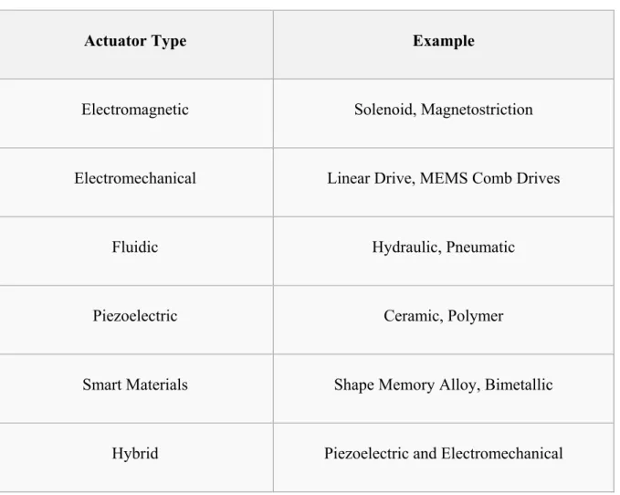
Actuators attached to the inside of morphing wings have been used to control the motions of the upper parts of morphing wings. These actuators can be operated by different energy sources such as electrical currents, hydraulic fluid pressures, or pneumatic pressures. Actuator systems have been incorporated on the aircraft, and were used to control the rudder, slats, flaps, brakes and landing gears for a long time. Table 1.1 presents a list of actuators types along with some typical examples (Zupan, Ashby, & Fleck, 2002).
Table 1.1 Classification of actuator types Taken from Zupan et al. (2002)
Actuator Type Example
Electromagnetic Solenoid, Magnetostriction
Electromechanical Linear Drive, MEMS Comb Drives
Fluidic Hydraulic, Pneumatic
Piezoelectric Ceramic, Polymer
Smart Materials Shape Memory Alloy, Bimetallic
Besides the list, two basic types of actuators can also be distinguished by their motions with respect to the controller command: “linear” and “nonlinear”. “Linear actuators” are the actuators whose motions are directly proportional to the controller’s command, while for the “nonlinear actuators”, this motion relationship is indirect to the controller’s command.
The linear actuators are further divided into two groups: “directly linear” and “indirectly linear” actuators.
“Directly linear” actuators can use the power from an engine without the need for any power reductions generated by a gearbox, pinion, belts or wheels. In this case, the electrical energy is used directly to achieve “linear motion”.
“Indirectly linear” actuators convert electrical energy into mechanical energy with the aim to generate torque or the required moving force. These are mostly “rotary actuators”.
To use indirectly linear actuators for a morphing wing, an adaptive system is required, which translates the rotary motion of the output shaft of a motor into a translational motion capable of ensuring the deformation (shape change) of the wing.
The applications of actuators in morphing wing technologies are indeed various. A Macro-Fiber Composite (MFC) actuator system was used to generate surface induced deformation in (Bilgen, Friswell, Kochersberger, & Inman, 2011). Two cascading active surfaces (upper and lower) were used to compose an airfoil. The authors aimed to obtain the highest possible lift coefficient, as well as the highest lift-to-drag ratio. Under the following wind tunnel conditions: Reynolds number of 127,000, a turbulence rate of 0.85% and air velocity of 15 m/s, the research showed that the lift-to-drag ratio was increased by using these composite actuators.
In (2011), Ohanian et al. used piezoelectric MFC actuators for a bimorphed configuration. This configuration was designed to change the aft part of a control surface cross section.
From its aerodynamic performance point of view, the approach achieved a larger change in the lift coefficient than the one using a hinged servo-drive flapped airfoil.
In (Usher, Ulibarri, & Camargo, 2013), Usher et al. introduced two approaches for designing and manufacturing the control surfaces. One approach involved the formation of flap-like structures by affixing the MFC actuators to the sides of a metal substrate, then attached it to the trailing edge. Another approach showed that MFC actuators were bonded to the wing in a direct way. The direct approach gave a better flexibility than the first approach. However, when they increased wing pressure, there are problems with tension loading, which still has to be solved.
In (1999), Pern & Jacob used the piezoelectric effect to control the airflow on the upper surface of an airfoil. THUNDER actuator, a kind of actuator that is built by binding a skinny sheet of piezoelectric ceramic under hydrostatic pressure between an aluminum electrode and a metal substrate, was created for the adaptive airfoil. The experiments showed that a maximum change of 1 cm of the wing’s leading edge was achieved when voltage was put on the actuators; and the amplitude of flutter vibration was also lower.
The piezoelectric effect was also used in (Munday & Jacob, 2002) and (Munday, Jacob, Hauser, & Huang, 2002). In both studies, piezoelectric actuators were used for a NACA 4415 wing. In the research works, the flow separation over the wing’s upper surface was investigated. The experimental results obtained in their laboratory revealed that with the help of the actuators, a reduction of 30-60% was found in the separated flow size with respect to the flow size on a shaped static wing. The researchers have also developed an approach using a wing airfoil that adapted to flow conditions, and its aerodynamic performance was improved over its upper surface for low Reynolds numbers with low speeds. Experimental tests with the wing was also carried out at different angles of attack, speeds and Reynolds numbers. Pressure signals were used to provide feedback signals to a real-time controller to extend the laminar flow over the upper surface of the wing, thereby delaying the transition zone.
In (LeBeau, Karam, Pern, & Jacob, 2010), the researchers investigated the low speed flow influence on an adaptive airfoil. In their research, the shape of the upper wing surface was changed by using piezoelectric actuators. At the Reynolds number of 25.000, the experimental results on this morphing airfoil revealed significant changes in its aerodynamic performance.
Other results obtained by Debiasi, Bouremel, Lu, & Ravichandran (2013) indicated that the changing of the shape of the airfoil’s upper surface was not the only way to enhance wing or aircraft’s aerodynamic performance. They have proposed in their research an airfoil whose upper and lower surfaces were adaptive. In their approach, piezoelectric actuators were built as integral parts of the skin. Wind tunnel tests showed that the hysteresis characteristics of the MFC actuators prevented the desired airfoil shape from being obtained. The researchers proposed using a closed loop control instead of open loop control to avoid and thus to cancel out the hysteresis motions of the actuators. Debiase and his co-workers also observed that the changes on the upper and lower surfaces of the wings equipped with the MFC actuators contributed in achieving better aerodynamic performance.
In (Vos, Barrett, de Breuker, & Tiso, 2007), the actuator’s performance was enhanced by using “compressed elements”. Post-Buckled Pre-compressed (PBP) piezoelectric bender actuators were used to replace conventional piezoelectric actuators on a reduced scale Unmanned Aerial Vehicle (UAV). These new PBP actuators aimed to control the UAV camber distribution, and therefore induced roll control. In comparison to conventional piezoelectric actuators, the new approach using PBP actuators gave around a factor of 2 to 15.25 degree peak-to-peak higher deflection, an increase of 38% of the roll control authority. The energy consumption was decreased from 24 W to 100mW, and the actuator weight was reduced from 59g to 3g.
Adaptive wing technologies for low-speed UAVs were summarized by Santhanakrishnan and his colleagues (2005). In these UAVs, actuators were integral parts of the wings. Their
summary presented the experimental results obtained from wind tunnel and flight testing for each method.
In (2010), Cosin, Angelo, Catalano, & Bonemer De Salvi have designed and manufactured a novel adaptive wing with enhancement of its aerodynamics properties. Span-wise and chord-wise wing deformations of the wing were allowed and their values were validated with wind tunnel hardware. An optimization algorithm was conceived to link the acquisition hardware to the desired positions given by the actuators.
In (Mashud, Rahman, Kaiser Ahmed, & Mujahidul Islam, 2010), an osccillating camber to control the flow separation was used. Piezoelectric actuators were attached on the upper surface of the wing to carry out the camber’s changes. Their tests indicated that the flow separation has occured at an angle of attack of 10 degrees when the actuators were located at 65%-75% of the chord length, and that this separation appeared at 15 degrees from the leading edge for an actuator placed at 55% to 75% of the chord length.
Shape Memory Alloy (SMA) is a kind of smart material and adaptive structures used as actuation systems in morphing wing systems. A flap morphing structure was investigated in (Kang, Kim, Jeong, Lee, & Ahn, 2012). These researchers used an SMA wire actuator to minimize the energy losses due to the geometrical discontinuities.
To further reduce aircraft fuel consumption, Brailovski, Terriault, Georges, & Coutu (2010) created an experimental laminar morphing wing that enhances the laminar flow region on the wing upper surface. The morphing mechanism of the wing moved its upper surface using an SMA actuator system.
Galantai(2012) investigated a scheme to improve an innovative wing equipped with SMAs for UAVs. They designed a lightweight wing that has a high degree of flight adaptability and thus an enhanced performance.
Two Neuro-Fuzzy control methods for open-loop morphing wing systems were studied as part of the CRIAQ 7.1 project (T. L. Grigorie & Botez, 2009; T. L. Grigorie, Botez, & Popov, 2009). These methods considered the pressure differences in relation to airfoil displacements. The two controllers were validated for 33 different flight cases. Another Neuro-Fuzzy controller method was proposed in (T. L. Grigorie & Botez, 2010). Using SMA hysteresis modeling of a morphing wing, these researchers created a new controller by taking advantage of different Neuro-Fuzzy controllers to correlate the sets of forces and electrical current values.
The wind tunnel results in real time of a morphing wing in (Andrei V Popov, Grigorie, Botez, Mamou, & Mébarki, 2010) showed the delay of the transition toward the trailing edge. The transition zone was already detected by means of an algorithm, explained and discussed in their previous work (Andrei Vladimir Popov, Botez, & Labib, 2008). Tests were performed for different angles of attack, Mach and Reynolds numbers, and showed that their method changed the shape of the morphing wing to an optimal formation under various wind tunnel airflow circumstances.
In (T. Grigorie, Botez, & Popov, 2013; T. Grigorie, Popov, & Botez, 2012), these researchers proposed another method for controlling the morphing wing’s shape in an open-loop design. In this method, the actuation mechanism consisted of two parallel actuation lines. A Fuzzy logic Proportional Derivative approach was used for the controller. The simulation and the experimental results showed that the controlled system worked well, with a position control error of less than 0.05 mm.
Another way to model and test the morphing wing system in its open-loop architecture was given in (Andrei Vladimir Popov, Grigorie, Botez, Mébarki, & Mamou, 2010). The researchers showed how this architecture could be used, and controlled in order to measure the pressure data on the upper surface of a flexible wing skin using Kulite pressure sensors, and to validate it through wind tunnel tests. They described the controller design and the actuation mechanism that they used to control the laminar flow region on the wing (T.
Grigorie, Popov, Botez, Mamou, & Mébarki, 2012a; Andrei Vladimir Popov, Labib, Fays, & Botez, 2008). Figure 1.1 shows this mechanism, that had two actuations lines, each line had three lines of SMA wires, along with a cam that was sliding span wise on a supporting plate. The rollers were used to translate the span-wise motion. A gas spring was used to restore the SMA after contraction. When the SMA was heated, the cam moved to the right and the actuator contracted. The reverse behavior of the SMA was observed by cooling the SMA. An On-Off Proportional Integral Controller was used to manipulate the vertical displacements of the actuators.
In order to validate the numerical controllers, two programmable power supplies were used to regulate actuation lines, as well as for a Quanser data acquisition card. To obtain the position feedback from the actuator, they implemented Linear Variable Differential Transformer potentiometers (LVDT) coupled to the inputs of a Quanser acquisition card. This system with the integrated controller was first tested on a bench test at their laboratory and then in a wind tunnel. The experiments were carried out under the conditions of a 2 degree angle of attack and a Mach number of 0.25. The results indicated that the transition point was moved successfully towards the trailing edge. However, the nonlinearity behaviour of the SMA actuators used for the morphing wing system in (T. Grigorie, Popov, Botez, Mamou, & Mébarki, 2012b) leads to the design of a new nonlinear controller.
Figure 1.1 Mechanical schematics of a morphing wing model using a SMA actuator Taken from T. Grigorie et al. (2012a)
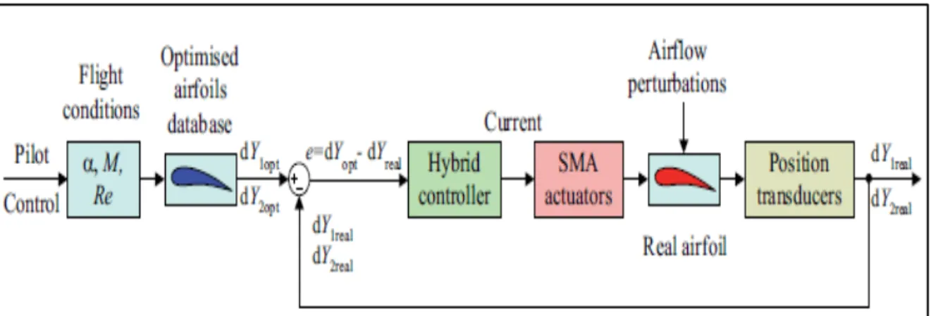
Thus, a nonlinear Fuzzy logic-Proportional-Integral-Derivative controller that is also a typical on-off controller (a hybrid controller) was subsequently designed and evaluated (T. L. Grigorie, Botez, Popov, Mamou, & Mébarki, 2012a). This hybrid controller technique was used to control the SMA actuators by regulating the electric current supplied; the aim of this technique is to cancel the deviation ɛ between the desired values of the vertical displacement that match up with the optimized airfoil displacements and the actual values thatachieved from the LVDT position transducers; in addition, this technique was used to solve the nonlinearities of the SMA actuators’ characteristics. Figure 1.2 shows the block diagram of the control system using the hybrid controller (T. L. Grigorie et al., 2012a). The experimental results of the nonlinear controllers were presented in (T. L. Grigorie, Botez, Popov, Mamou, & Mébarki, 2012b).
Figure 1.2 Block diagram of the controlled morphing wing system Taken from T. L. Grigorie et al. (2012a)
In the listed references above, the LARCASE team worked on the CRIAQ 7.1 project called “Controller design and validation for laminar flow improvement on a morphing research wing- validation of numerical studies with wind tunnel tests”. In this thesis, we work on the MDO 505 project named “Morphing architecture and related technologies for wing efficiency improvement”. The objective is to move the transition point toward the trailing edge by using another type of actuation system and a unique combination of control methods such as Fuzzy and Neuro-Fuzzy logic methods. The previous working experiences in dealing
with problems of morphing wing and actuation system would be a very useful source to consider, and to take it as a reference.
PROBLEMS AND OBJECTIVES
2.1 Problems
In the previous CRIAQ 7.1 project, the wing was idealized as a rectangular box, that had no structural constraints. For that wing, the SMA actuators were consuming a high amount of energy. In the present CRIAQ project, a wing-tip of a real aircraft is considered, that has already structural constraints imposed by its designer and manufacturer (Bombardier). On this wing, electrical in-house actuators were implemented.
In this project, the challenge for the realization of the morphing wing system is that its airfoil needs to improve its aerodynamic performance under different flight conditions. In other words, the system needs to reduce its drag while maintaining constant lift to improve its aerodynamic performance. The most promising approach is to move the flow transition region closer to the trailing edge, which would increase the lift-to-drag ratio. In the implementation of control methods for morphing wing, some of the difficulties that can be anticipated are the nonlinearities of the whole system, and the integration and synchronization of the wing tip control system. Original control methods to solve these problems will be developed and investigated.
2.2 Objectives and Project Description
The CRIAQ MDO 505 project involves two teams of partners from two countries: Canada and Italy. The Canadian team is comprised of partners from the Ecole de Technologie Superieure (Montreal), Ecole Polytechnique de Montreal, Thales, Bombardier, and the Institute of Aerospace Research of National Research Council of Canada (IAR-NRC). The Italian partners are partners from CIRA and the University of Naples Federico II. The main goal of the project was to build a wing-tip controller system of a Bombardier aircraft, and to validate it via wind tunnel and flight tests. The wing tip prototype system, including a
morphing wing and a morphing aileron were designed, manufactured and tested. Various types of actuators and sensors were used to control the morphing wing tip mechanisms of the system, with the following objectives:
• Improving the wing tip-aileron aerodynamic performance at low subsonic speeds; • Extending a laminar flow region while avoiding massive boundary layer separation.
Wind tunnel test data were collected at the IAR-NRC aerodynamics laboratory to validate the morphing wing-tip system. Numerical investigation of the aero-elastic capability of the prototype was performed by the aerodynamics team to verify the flutter stability boundaries and to eliminate any eventual system buffeting phenomenon occurring at transonic speeds.
The wing tip has been equipped with electrical actuators, and with Kulite sensors that were used to measure the pressures. The main objective of the thesis was to design a robust and reliable control system for the morphing wing tip system. New methodologies presented in this thesis were developed to morph the active structure (skin composite) shape for predefined flight conditions, and to integrate and implement the aerodynamic and structural morphing wing-tip technologies in the control system.
ORIGINALITY AND METHODOLOGY 3.1 Originality
Several researchers have been working on improving the airfoil flow to enhance the dynamic performance of morphing aircraft systems. However, most of the studies have used intelligent materials for the actuation of the morphing systems. The CRIAQ MDO 505 research team decided to use Brushless Direct Current (BLDC) motors for the actuation mechanism. BLDC motors are miniature permanent magnet synchronous motors that offer many advantages such as high flexibility, good controllability, high power density, high efficiency, large torque to inertia ratio, as well as light weight. Compared to Permanent Magnet Synchronous Motors (PMSMs), BLDC motors are less expensive as they have concentrated windings and use Hall-effect sensors, which are cheaper than the position sensors required by PMSMs, such as optical encoders.
This thesis considers, for the first time, using two types of ANFIS controllers to control the actuators in a Bombardier aircraft morphing wing-tip system for both cases; those in which the aileron moves and when it stays still. Both controllers were experimentally tested in a wind tunnel with a morphing aileron installed on a wing. These two controllers, based on a Neuro-Fuzzy methodology, offer promising approaches for actuator control. The first controller is built with trapezoidal-shape input membership function and constant output membership function. The second controller is built with bell-shape input membership functions and linear output membership functions. Maxon industrial drives are used to implement these algorithms into the real-time morphing wing-tip system. The control architecture using National Instruments systems in real time is also proposed and implemented for the first time in the morphing wing-tip system. Problems encountered during the Wind Tunnel Test validation are also mentioned and solved.
3.2 Morphing wing and aileron system 3.2.1 Morphing wing-tip model
The wing-tip model in this project has a chord of 1.5 meters and a span of 1.5 meters, which is equivalent to a full-scaled part of the wing and aileron of a regional aircraft. The wing model is equipped with an aileron, and a morphing skin made of composite materials on the wing’s upper surface.
Figure 3.1 indicates the position of the wing-tip model on an aircraft wing, in which the wing-tip part is located between the fuel tank part and its winglet part. Figure 3.2 shows a cross section (airfoil) of this wing-tip model. The ailerons are used to control the aircraft in roll motion (or motion around the aircraft’s longitudinal axis). The lower surface of the wing is made of aluminum, and is large enough to accommodate a strain gauge transducer, an actuation system, sensors, as well as a cabling system for these sensors.
Figure 3.1 Position of the morphing wing-tip on the aircraft wing
The lower surface was produced by the mechanical team of the CRIAQ MDO 505 under the leadership of Dr. Simon Joncas from ÉTS, and in collaboration with Bombardier team. The
morphing wing-tip was designed and manufactured by Bombardier Aerospace as it represented a real Bombardier wing.
Figure 3.2 Wing-tip structure
3.2.2 Actuators
The morphing wing’s actuation system is composed of four actuators fixed inside the wing. Four BLDC motors serve as electrical motion sources, one for each actuator. These Maxon-type motors have the characteristics indicated in Table 3.1. To convert the motors’ rotary motion to the vertical motion of the wing’s upper surface, each actuator has a gearing system equipped with a nut, which is joined to the shaft of its BLDC motor.
As known, a brushless DC motor is a synchronous electric machine driven by DC electricity. BLDC motors can be used in single phase, 2-phase or 3-phase power stage. The BLDC motors used in the project are constituted as 3-phase power bridges corresponding to, three windings of the stator. Figure 3.3 shows the BLDC motor in its cross section.
Table 3.1 BLDC motor’s characteristics
Figure 3.3 BLDC motor
The BLDC motors use the interaction between the stator flux with the rotor flux, generated by permanent magnets, to create the torque. Because of the fact that the rotor flux is induced by the stator poles flux, the stator pole position of a BLDC motor needs to be checked to
Nominal voltage 12 volts
No load speed 4610 RPM
No load current 75.7milliamperes
Nominal Speed 2810 RPM
Nominal torque (maximum continuous torque) 25.1 millinewton-meter Nominal current (maximum continuous torque) 1 ampere
Stall torque 84.1 millinewton-meter
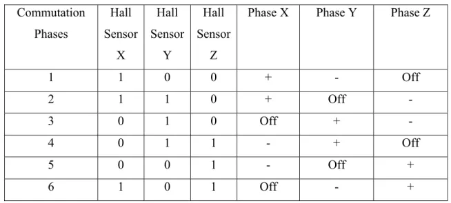
control its 3 motor phases. Thus, a 6-step commutation configuration is built by a motor controller. These commutation steps, or commutation phases, help to create a rotational electromagnetic field, which provoke the rotation of the rotor permanent magnets and move the motor shaft. In order to create these commutation phases, six power transistors corresponding to six commutation steps are used for 3 phase’s power stages (X, Y and Z). Among these 3 phases, only two phases are active at the same time, the remaining phase stays unpowered (or off). One of these two active phases has positive or negative voltage, while the remaining active phase has negative or positive voltage, respectively, and create 6 commutation steps as shown in Table 3.2. The Hall-effect sensors determine the positions of the rotor. The stator flux vector was based on the positions of rotor to change so that the angle between the stator flux and the rotor flux remains as close as possible to 90 degrees. In that way, the rotor of the BLDC motor keeps moving. Table 3.2 and Table 3.3 shows the 6 commutation phases for two cases: clockwise rotation and counterclockwise rotation. The values of Hall-effect sensors are also presented: 0 means the Hall sensor is inactive, while 1 denotes that Hall sensor is active.
Table 3.2 Commutation Phases for clockwise rotation Commutation Phases Hall Sensor X Hall Sensor Y Hall Sensor Z
Phase X Phase Y Phase Z
1 1 0 0 + - Off 2 1 1 0 + Off - 3 0 1 0 Off + - 4 0 1 1 - + Off 5 0 0 1 - Off + 6 1 0 1 Off - +
Table 3.3 Commutation Phases for counter-clockwise rotation
Figure 3.4 shows the stator flux vectors in the 6-step commutation phases. “XYZ” denotes the Hall-effect sensor output. The green arrows denote the stator flux vectors. Figure 3.5 demonstrates the behaviors of the BEMF motor phases corresponding to the changes of commutation phases. BEMF denotes the Back ElectroMotive Force or the counter Electromotive force of the three motor phases, which is the “voltage or electromotive force created by the relative motion between the armature of the motor and the magnetic field generated from the motor’s windings” (Wikipedia, 2017a). S1 to S6 are the six transistors used in the inverter to control the commutation phases. , and are the voltages of the phases X, Y, Z to Neutral, respectively. is the DC link voltage. Each commutation phase is reassigned every 60 electrical degrees.
The commutation process can be explained as follows : Consider the clockwise rotation for the commutation phase number 1 as shown in Table 3.2, the Hall sensor state is XYZ [100] as seen in Figure 3.4; in other words, the phase X is connected to the positive voltage source by opening the transistor S1 or = (see Figure 3.5); the phase Y is connected to the negative voltage − by opening the transistor S5 or = − , the phase Z is off and unpowered (see Figure 3.5);. When the rotor moves to a particular position, the Hall sensor’s state changes its values from the previous state XYZ [100] to the next state XYZ
Commutation Phases Hall Sensor X Hall Sensor Y Hall Sensor Z
Phase X Phase Y Phase Z
1 1 0 0 - + Off 2 1 0 1 Off + - 3 0 0 1 + Off - 4 0 1 1 + - Off 5 0 1 0 Off - + 6 1 1 0 - Off +
[110] as seen in Figure 3.4, and the corresponding voltage is applied to each phase as shown in Table 3.2.
Figure 3.4 Stator flux vectors
Figure 3.5 Six step Hall sensor outputs and motor phases
In order to control the speed and direction of the motor, Hall-effect sensors plays a very important role. However, the Hall-effect sensors do not offer the real time angular position feedback when it can only provide information for each 60º movement in the rotor’s position and within each electrical cycle. Thus, here encoders are used to compensate the drawback of Hall-effect sensors. The Hall sensors are used for the commutation of the BLDC motor, while the encoders track the position, speed and rotation of the motor, and convert the angular position to an analog/digital code or a pulse, and send it to the BLDC drives (in this project the BLDC drives are the Maxon drives). A BLDC controller is then used to control the active state of the transistors (open or closed) based on the signals received from the encoders and Hall sensors.
Figure 3.6 shows the way in which actuators are attached inside the wing. This figure also shows the positions of the four actuators, and the cabling system inside the wing.
3.2.3 Sensors
Control methods are implemented in the actuation system with the aim to change the surface of the wing until it reaches its desired optimal shapes. The desired wing surface displacements were calculated by our aerodynamic team to achieve the optimum airfoil wing shapes. The displacements differ as a function of Mach numbers (M), angles of attack (α) and aileron deflection angles (
δ
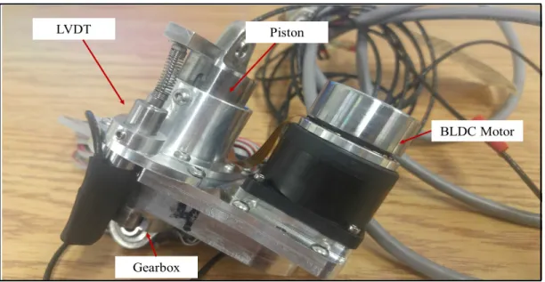
ail). In the control loop, as shown in Figure 3.7, the morphing wing-tip system is controlled by the position feedback signals received from the LVDT sensors. The LVDTs (Wikipedia, 2017b) are a kind of electrical transformers, which are used to measure linear positions, thus wing surface displacements. The sensors are attached along with the piston of the actuators so that any movements of the actuators are recorded and observed. Figure 3.8 shows an actuator with this LVDT mechanism. In our research, the LD340-6 series are used with a range of mechanical travel of ± 6mm (wing skin displacements). These values of ± 6mm were chosen as function of the aero-structural interactions and were calculated by the aerodynamic and structural teams. The specifications of an LD340 can be found in (Omega, 2014).Figure 3.8 An actuator with LVDT sensors
To observe the behavior of the morphing wing’s skin and to evaluate the improvement of the system’s aerodynamic performance, Kulite sensors are used to record the pressure changes on the skin surface. The Kulite sensor is a kind of pressure transducer that generates an electrical output proportional to the measured pressure. The sensor systems were tested earlier in the Price Païdoussis Subsonic Wind Tunnel at the LARCASE, along with a demonstration model of the morphing wing’s upper surface. In our research, we used 32 Kulite XCQ-0162 series sensors to measure pressures of a 0.35 to 5 psi range. The Kulite piezoelectric sensors are also used to detect the flow transition from the laminar to turbulent regimes. The specifications of such a Kulite sensor is shown in (Kulite, 2015).
3.2.4 Ailerons Control
The motions of the aileron actuation system are less complicated and easier to control than those of the wing. The deflection range of the aileron is between -6 to +6 degrees. This range of the aileron was determined by aerodynamic constraints and security limitations in the wind tunnel. Two types of ailerons were considered: a rigid aileron, which was built by a Canadian team, and a morphing aileron, which was designed, manufactured and controlled by an Italian team. The type of aileron did not affect the movement of the morphing wing
skin because ailerons were controlled separately by their controller systems, which were different from the wing’s actuation system. The aileron actuation system is presented in details in the next section 3.3. The system controlling the shape of the morphing aileron was designed and manufactured by the Italian team. The system controlling the interaction between the morphing wing and the aileron (rigid or morphing) is described in Section 3.4.
3.3 Operating System Hardware and Software
This section presents the hardware and software that we used to carry out the wind tunnel tests. All equipment used to control the morphing wing-tip system is shown in Figure 3.9, as it is configured in our LARCASE laboratory. Two kinds of industrial communication networks are used in the system: Ethernet and CAN.
Ethernet is a link layer protocol that is used to connect the real-time operating system in the embedded controller, NI PXIexpress-8135, with a Host PC and the Kollmorgen Drive, which is used to control the movement of the aileron.
The other connection network, CAN network, is used to connect the Maxon drives (EPOS 24/5) with the embedded controller. The communication issues among these different types of equipment are discussed and presented in detail in (Guezguez, 2016). In this thesis, we describe the general concept and purposes of the equipment in the system in a limited extent. Thus, the system includes:
1. NI SCXI-1000 & SCXI-1540 Add-on LVDT Conditioning Modules, which filter and process LVDT signals.
2. NI PXIexpress-8135 is an embedded controller for the PXI express system, which is used for system computation. To monitor the embedded controller to control program deployment, system state and data logging, a Host PC is connected via an Ethernet network using a TCP/IP communication protocol.
3. Maxon drive EPOS2 24/5 (Easy to use Positioning System, second generation, 24V-5A) is a “small-sized, full digital smart motion control unit” (MaxonMotor, 2016). This drive is used for positioning of BLDC motors with digital Hall-effect sensors and encoders. The drive is designed as a “slave node” in a CANopen network, and can be monitored via any USB or RS232 connection. In this research, we use a Maxon drive as a supported controller because of its functionality in reducing torque ripple, its low noise and its integrated current and speed control. Ten modes are implemented in the drive, including “homing mode”, “profile position mode”, “profile velocity mode” and “position mode”. We used the position mode for our work. In this mode, we can set a new value for the position control loop without setting up a new profile, which makes easy the control of the motion of the actuators (MaxonMotor, 2014).
4. The CPX400 power supply provides a fixed 24V for each BLDC motor.
5. The computer screen of the Host PC is used to observe the connection between devices and to visualize the real-time system/hostPC deployment process.
6. Kulite add-on Conditioning Modules, which filter and process Kulite signals.
Because we have two kinds of ailerons, the equipment used to control these ailerons is also different. For a rigid aileron, its motions are controlled by a BLDC servo motor supported by a Kollmorgen® drive. In the same way as the other BLDC motors, these motors use Hall-effect sensor feedback to detect the rotor’s position and initiate power stage phases. Encoder sensors provide the position and speed feedback in real time and give the drive the precise angular position and speed of the motor.
The motor is then controlled by a Proportional Integral Derivative (PID) algorithm implemented in the Kollmorgen® drive to reach desired deflection aileron angles. Because of the fact that we only need to deflect the aileron for a certain number of predefined aerodynamic shapes, we decided to create sets of fixed aileron positions. The “motion task” feature in the Kollmorgen® drive allow us to create the sets of desired displacements, speed that assist the aileron actuation system to reach the desired deflection angles. The user then only needs to input the motion task number on an Ethernet interface, and the actuation system moves the aileron to its required position.
When using a morphing aileron, a DSPACE DSP controller was used to move the aileron. The DSPACE system has its own graphical interface. The real-time control strategy was developed using MATLAB/Simulink software, and then is converted into C code using the C/C++ compiler. The code was implemented into the DSP board, and allows the user to control the system in real time.
The whole wing-tip system and the ailerons are shown in Figure-A I-1 and Figure-A I-2 in ANNEX I. The software used to carry out the experiments is listed in Table 3.4.
Table 3.4 Software List
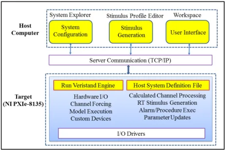
Each software package and its function in our experiments is presented in detail in the following paragraphs. The main software used to control the real time testing is NI-Veristand, from National Instruments. It provides us “a framework for real-time testing applications” (NationalInstruments, 2015b). Figure 3.10 gives an overview of the NI Veristand architecture, inspired by the introduction of NI Veristand (NationalInstruments, 2015a, 2016). This architecture includes three windows on the Host Computer/PC: the Workspace, the System Explorer and the Stimulus Profile Editor. The Target, which here is NI-PXIexpress-8135, has the mission of hosting the definition files and running the NI Veristand Engine.
Software Name Description
Matlab® Simulink Used for control modeling; these control models will be further
integrated with NI-VeriStand® to control the system in real time.
LabVIEW® Used for developing custom devices in order to acquire the required signals. LabView® is also used for developing models integrated with NI-VeriStand®
NI-VeriStand® Used for real-time testing applications. The main objective is to configure the real-time engines to implement tasks such as data acquisition, conditioned measurement, etc. NI-Veristand® also allows users to deploy/import control models, and to create run-time interfaces with the real-run-time equipment of National Instruments.
Figure 3.10 The NI Veristand architecture Adapted from National Instruments (2015a, 2016) Several important definitions of this architecture are listed below:
1. System Explorer
The purpose of the window is to create a system definition. All of the settings such as hardware I/O (Input/Output), the functional models imported from LabVIEW and Matlab/Simulink, etc.… are created and edited in the System Explorer. The system definition file, therefore, includes the running rate of the system, data acquisition devices, channel configurations, simulation models, active alarms and procedures, as well as system mappings. We present here several key sections in the system definition file:
• Targets: Contains the targets in which we want to deploy our program. Additional Hardware (I/O) can be added here, including DAQ and FPGA. In our experiments, the Target is NI-PXIexpress-8135 with the additional modules NI 1000, SCXI-1540 Add-on LVDT Conditioning Modules and Kulite Modules;
• Simulation Models: “Mathematical representation of a real-world system” (NationalInstruments, 2015a). These models are created separately in Matlab/Simulink. Inputs/Outputs of the models are assigned to the Inports/Outports on a Target via System Mapping, and to operate the real-time control of the targets;
• System Mapping: Links the source with destination channels or custom devices; • Custom Devices: Channels/modules that are created to serve a specific purpose.
LabVIEW is used here to create Custom Devices for the sensor data acquisition; • Calculated Channels: These channels are used to modify the values of other system
channels according to the calculated requirements of the user such as calibrated values of LVDTs;
• Active Alarms/Procedures: Utilized to inform the user about current events and to show the list of actions that can be executed on the Target.
In order to implement the system definition file on the Target, the Veristand Gateway is used, which creates a TCP/IP communication channel to communicate with the VeriStand Engine and synchronizes with the definition file that is currently running on the Target.
2. Stimulus Profile Editor
The Editor is a tool to create stimulus profiles, which allow users to execute desired tasks and tests deployed in the Veristand Engine in an automated way. Users can create lists of steps, loop structures, variables and conditional statements that they want the NI Veristand Engine to perform. Users also can assign multiple logging tasks, independent logging rates and trigger conditions to their stimulus profiles. We use Stimulus Profile Editor to perform the automated calibration process, which is discussed and presented in Chapter 4.
3. Workspace
The Workspace is a kind of user interface, which allows users to carry out their real-time tasks. The system definition is deployed here, so that users can drag-and-drop different objects for different purposes in the run-time user interface, and then map the objects to their desired channels. The workspace or the user interface used in the Wind Tunnel Test is shown in Chapter 4.
4. NI Veristand Real-time Engine
This NI Veristand Real-time Engine is a “non-visible execution mechanism” (NationalInstruments, 2015c) that monitors the timing of the entire system and the communication issues between the Host PC and the Target. This Engine has multiple time loops using real time FIFOs (First In-First Out) mechanisms to transfer data packages between the them. It also decides which system definition file is allowed to run and carries out the execution of hardware I/O, models, test, procedures, etc. in this system definition file.
3.4 Controller Design and Actuation System
This section introduces the controller design and the actuation mechanism of the morphing wing-tip system. A portion of this work has already been published (D. H. Nguyen, Tchatchueng Kammegne, & Botez, 2015; D. H. Nguyen, Tchatchueng Kammegne, Botez, & Grigorie, 2016).
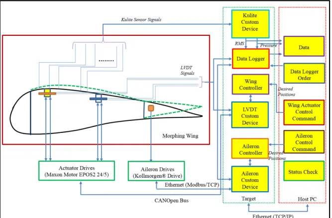
3.4.1 System Control Architecture
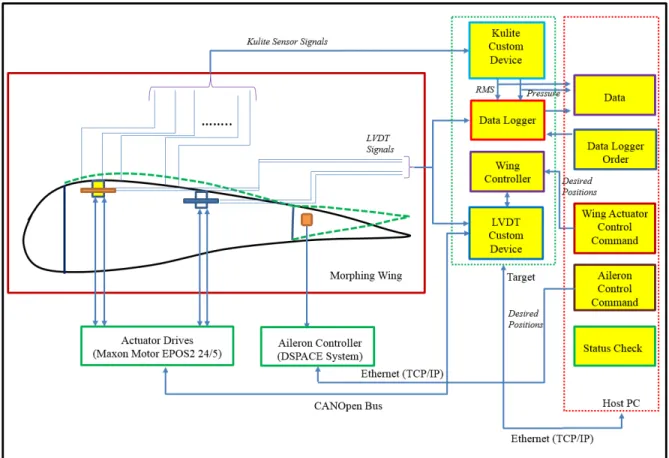
Figure 3.11 indicates the general architecture of the whole controlled morphing wing-tip system, showing the morphing wing-tip system with a rigid aileron. The architecture is similar to the case using a morphing aileron, except that the morphing aileron control is performed with a DSPACE system, as shown in Figure 3.12. The morphing aileron was controlled by the Italian team involved in the CRIAQ MDO 505 project.
The system introduced here has three main parts: the morphing wing-tip and aileron, an NI time controller (PXIe-8135) and its extended modules, and the Host PC. In the NI real-time controller, NI Veristand Custom Devices are created to acquire the pressure data from Kulite sensors and the position feedback from LVDT sensors. The actuation system inside the morphing wing-tip is monitored by a Host computer via an NI Veristand Workspace/GUI.
All of the current system’s status is shown in the GUI so that the users know the current positions of the whole actuation system. After the deployment of the whole system on the Target, the desired positions are set by the users and sent to the wing and aileron controller, which sends instructions to the NI Custom Devices of their position sensors and their drives. The drives then convert the digital commands into analog and transfer these signals to the actuators. The position feedbacks of the actuators are transmitted to the custom devices before being sent back to the controllers for monitoring purposes. All of the data is recorded via data logger under a data logging command in the Host PC.
Figure 3.11 General architecture of the morphing wing and rigid aileron controllers
In the morphing aileron case, due to the differences in the actuation systems and digital signal processing hardware/software of the aileron motion controllers, we decided to control the actuation systems of the morphing wing and the morphing ailerons separately. This