UNIVERSIT´
E DE SHERBROOKE
Facult´e de g´enie
D´epartement de g´enie m´ecanique
D´
EVELOPPEMENT D’UN DRONE
AQUATIQUE `
A D´
ECOLLAGE ET
AMERRISSAGE VERTICAL
M´emoire de maitrise
Sp´ecialit´e : g´enie m´ecanique
Richard-Alexandre PELOQUIN
Sherbrooke (Qu´ebec) Canada
MEMBRES DU JURY
Alexis LUSSIER DESBIENS
Directeur
David RANCOURT
´ EvaluateurMathieu PICARD
´ EvaluateurR´
ESUM´
E
Dans le but d’augmenter la dur´ee de mission de v´ehicules a´eriens sans pilote, une strat´egie de recharge solaire est envisag´ee en utilisant les lacs comme lieux d’escale et de recharge. Le concept d´evelopp´e est en mesure de d´ecoller et d’amerrir verticalement sur l’eau. Le prototype fabriqu´e consiste en une aile reli´ee `a un corps central rotatif minimisant les composantes ajout´ees grˆace `a une manœuvre de d´ecollage passive. Un mod`ele dynamique du d´ecollage valid´e par des essais exp´erimentaux sert d’outil de conception. L’amerrissage est ex´ecut´e en plongeant et ne requiert aucun contrˆole complexe ou pliage des ailes. La r´esistance structurelle de l’aile est confirm´ee par l’analyse des acc´el´erations `a l’impact. `A ce sujet, un mod`ele pr´edictif est d´evelopp´e pour diverses vitesses d’impact. Le prototype final a ex´ecut´e plusieurs d´ecollages r´ep´etables et a r´ealis´e des cycles d’op´erations complets de vol, de plongeon, de flottaison, et de recharge.
TABLE DES MATI`
ERES
1 INTRODUCTION 1
1.1 Mise en contexte et probl´ematique . . . 1
1.2 Question de recherche . . . 3
1.3 Objectifs du projet de recherche . . . 3
1.4 Contributions originales . . . 4
1.5 Plan du document . . . 4
2 ETAT DE L’ART´ 5 3 M´ETHODE DE D´ECOLLAGE ET D’AMERRISSAGE VERTICAL 9 3.1 Abstract . . . 11
3.2 Introduction . . . 11
3.3 Dynamics of Passive Takeoff . . . 13
3.3.1 Motion . . . 14
3.3.2 Forces . . . 15
3.3.3 Equation of Motion (EOM) . . . 17
3.3.4 Validation . . . 18
3.3.5 Design . . . 21
3.4 Righting after capsize . . . 23
3.5 Dive Landing . . . 24
3.5.1 Impact Modeling . . . 24
3.5.2 Structural Sizing . . . 27
3.6 Implementation and Results . . . 28
3.7 Conclusions and Future Work . . . 30
4 CONCLUSION 31
LISTE DES R´EF´ERENCES 33
LISTE DES FIGURES
2.1 Comparaison des diff´erentes plateformes aquatiques sur le march´e . . . 7 3.1 Proposed concept for the vertical takeoff . . . 12 3.2 Time lapse of SUWAVE’s vertical takeoff sequence. . . 13 3.3 Diagram of the simplified wing (W), center body (B), reference frames and
forces included in the dynamic takeoff model. . . 14 3.4 Measured static thrust as a function of time, filtered with a 12th order zero
phase butterworth filter with a cutoff frequency of 8 Hz, and its correspon-ding first order fit. . . 15 3.5 The 3D trajectory of the prototype during takeoff as captured by Vicon is
mostly planar. Frames are spaced by 0.12 sec. . . 19 3.6 Comparison of the trajectory of point Wo in simulation and during three
distinct experimental takeoffs for time varying from 0 to 1 sec. . . 20 3.7 Time behavior of angles qW and θB. Note that the bracket latches with the
wing around t = 0.4 sec. . . 20 3.8 Simulation of three takeoffs using the parameters of Table 3.1. The value of
the motor angle qC is changed between −0.5 deg (flip) and −9 deg (dive).
Both cases latch at an angle outside of the range of 40 to 60 degrees. Refer to Fig. 3.9 for the acceptable range of qC. . . 21
3.9 Influence of each parameters on the success of takeoff. The light gray zone corresponds to a latching angle over 60 degrees while the dark gray zone corresponds to a latching angle below 40 degrees. The white area represents a successful takeoff. Units are expressed in the SI system and degrees. The black dot locates the characteristics of the physical prototype. . . 22 3.10 Simulation results of the wing righting. Refer to supplementary material to
see experimental results. . . 23 3.11 Measured x accelerations for various impact velocities. The accelerations in
y and z are illustrated to show that the impact occurs mainly in x. . . 24 3.12 Representation of the simplified wing, notice the submerged volume and
the frontal area . . . 25 3.13 Impact model as fitted with the experimental results. Individual
compo-nents of the acceleration are also illustrated (CB = 0.6, CV = 50). . . 26
3.14 Graph of peak acceleration vs impact velocity. The parametric model (Eqn. 3.12, CB = 0.6, CV = 50) is compared with the experimental results. Mean
re-sults are represented by the ∗ symbol while the error bars represent the maximum and minimum peak accelerations obtained for five impacts at that velocity. . . 26 3.15 Representation of a half wing for stress analysis. The equations for the
moment and the inertia are expressed as a function of geometry. . . 27 3.16 Representation of the various component of SUWAVE. . . 28 3.17 Cutaway view of the center body. The position of the center of mass is shown. 29
LISTE DES TABLEAUX
2.1 Forces et faiblesses de chaque cat´egorie d’a´eronef pouvant op´erer `a partir de l’eau . . . 6 3.1 Physical properties of the built prototype . . . 19 3.2 Mass budget of the prototype . . . 29
CHAPITRE 1
INTRODUCTION
1.1
Mise en contexte et probl´
ematique
Le d´eveloppement rapide des v´ehicules a´eriens sans pilote (de l’anglais, UAV) a permis leur utilisation dans diverses applications. En raison de leur coˆut plus faible, ils sont maintenant pr´ef´er´es aux avions avec pilote pour ´etudier les zones agricoles [15] et foresti`eres [41]. Ils sont ´egalement utilis´es pour la surveillance de la faune [17], la prise d’´echantillons d’eau [29] et la surveillance de fronti`eres [14]. Finalement, leur simplicit´e d’utilisation permet leur d´eploiement rapide en aide aux premiers r´epondants en cas de d´esastre humanitaire [9]. La plupart des UAV existants capable de longue port´ee sont des drones `a voilure fixe, comme les avions. Il existe aussi des drones `a voilure tournante, tels les h´elicopt`eres. Les h´elicopt`eres, bien que plus agiles, ne sont pas capable de voler aussi loin puisque leur effi-cacit´e n’est pas aussi bonne. Au sein des avions, il y a un compromis entre les plateformes de grande envergure, capables de voler plusieurs heures et les drones plus petits, limit´es dans leur temps d’op´eration. D’un cˆot´e se retrouvent les avions pleine grandeur, souvent de type militaire. On y retrouve par exemple le Global Hawk de Northrop Grumman [26] et le Predator B de General Atomics [13], tous deux ayant une envergure de plusieurs dizaines de m`etres et pouvant parcourir plusieurs milliers de kilom`etres. Ce type de drone n´ecessite une ´equipe compl`ete de pilotes sp´ecialis´es pour les contrˆoler, ce qui rend leur utilisation plus restreinte. `A l’autre bout du spectre, se situent les petits avions, souvent ´electriques et `a d´eploiement manuel, dont l’envergure tourne autour du m`etre. Le Wasp III d’AeroVironment [1] ainsi que plusieurs avions de loisir et de recherche, tels le Zagi [50], le eBee [37], et le Disco [32] en font partie. Ces avions, bien que faciles d’utilisation, par-courent de faibles distances (moins de 50 km). Le terme autonomie sera ici utilis´e pour parler de distance, plutˆot que de temps de vol. Cette faible port´ee limite leur utilisation pour des missions de longue dur´ee ou sur de grands territoires.
´
Etant donn´e que les drones de petite taille sont majoritairement ´electriques, il est possible d’augmenter leur autonomie en y installant des panneaux solaires. Cependant, contraire-ment aux avions de grande envergure, l’ajout de panneaux solaires sur de petits drones ne permet pas de voler en continu [27]. Bien que la masse de la structure diminue au cube du facteur d’´echelle, les panneaux solaires gardent la mˆeme ´epaisseur, leur masse repr´esentant
2 CHAPITRE 1. INTRODUCTION une plus grande proportion de la masse totale du v´ehicule. Il y a ´egalement moins d’aire disponible pour leur installation. En plus, `a mesure que la taille des drones est r´eduite, les performances a´erodynamiques diminuent l´eg`erement, tout comme le rendement du syst`eme de propulsion. Pour ces raison, les drones de petite envergure doivent donc se poser pour changer leur batteries ou se recharger avant de red´ecoller pour poursuivre leur mission.
Pour effectuer des missions de longue dur´ee de fa¸con autonome, la s´election des zones d’atterrissage devient donc une tˆache particuli`erement importante. Il doit s’agir d’une zone `a la fois d´egag´ee et facile d’acc`es. Plusieurs chercheurs ont d´evelopp´e des plateformes capables de se poser et d’atterrir `a divers endroits pouvant ˆetre propices `a la recharge solaire. Le S-MAD [21] de mˆeme qu’un micro planeur [18] se posent sur les surfaces verti-cales. D’autres prototypes capable d’atterrir sur des cˆables [5, 24] ont aussi ´et´e d´evelopp´es. D’autres UAV r´eussissent aussi `a se poser sur des surfaces en mouvement, comme le pont de navires [47]. Toutefois, pour toutes ces techniques, il devient tr`es difficile d’identifier des zones d’atterrissage ad´equates dans un environnement r´eel sans l’utilisation de capteurs embarqu´es lourds (ex : cam´era, lidar) et le traitement de donn´ees complexes.
Pour ´eviter ces complications, il devient n´ecessaire de trouver des lieux facilement rep´erables et d´epourvus d’obstacles. Dans plusieurs r´egions du monde, les lacs repr´esentent un en-droit propice puisqu’ils sont plats et que leur position est bien document´ee. Au Canada par exemple, 9% de sa superficie de 10 millions de km2 est recouverte de lacs voyant peu d’activit´e humaine [25]. De plus, des calculs pr´eliminaires bas´es sur des observations hy-drographiques [22] montrent qu’une autonomie de seulement 20 km est n´ecessaire pour traverser le Qu´ebec du nord au sud (1900 km) en faisant escale sur les lacs. Cette tˆache est r´ealisable par la plupart des petits drones existants.
Les nouvelles applications dans lesquelles les drones sont maintenant utilis´es n´ecessitent des plateformes toujours plus agiles, rapides et endurantes. Toute modification am´eliorant leur fonctionnalit´e doit se faire sans impacter les performances en vol. Pour les utilisations aquatiques, en plus d’une grande autonomie, les nouvelles plateformes doivent op´erer dans des zones restreintes, souvent encombr´ees d’obstacles.
Les hydravions sont souvent utilis´es dans le cadre de missions aquatiques. Toutefois, ils n´ecessitent de longues pistes de d´ecollage et d’amerrissage, rendant leur utilisation difficile en environnement restreint. De plus, lorsque utilis´es comme petits drones, ils pr´esentent plusieurs d´efis. Proportionnellement, les vagues sont plus grosses, ce qui rend difficile la prise de vitesse requise pour le d´ecollage [31]. Aussi, leur masse faible et leur ailes hautes
1.2. QUESTION DE RECHERCHE 3 les rendent susceptibles `a se retourner. Une fois `a l’envers, ces v´ehicules n’ont aucun moyen de se r´etablir, ce qui met fin `a leur mission et n´ecessite une intervention humaine.
Un d´ecollage et un amerrissage vertical pourrait permettre d’augmenter le nombre de zones de mission propices. ´Egalement, cela permettrait d’am´eliorer la fiabilit´e de ces manœuvres. En effet, un drone ayant ces capacit´es pourrait avoir acc`es `a de nouveaux lieux d’int´erˆets restreints, comme un lac entour´e de hauts arbres, une rivi`ere ´etroite ou mˆeme une piscine. Cela lui permettrait d’accomplir des tˆaches plus vari´ees, menant `a une utilisation `a plus grande ´echelle de la plateforme.
La solution ´evidente permettant le d´ecollage et l’atterrissage vertical est l’utilisation d’un drone `a voilure tournante, tels un h´elicopt`ere ou un quadrotor. Cependant, leur efficacit´e est nettement inf´erieure `a celle des drones `a voilure fixe [11]. Par ailleurs, ils ne poss`edent pas de grandes surfaces o`u installer des panneaux solaires. Cela les rend moins int´eressantes pour la r´ealisation de missions de longue dur´ee n´ecessitant une grande autonomie.
1.2
Question de recherche
En lien avec les nombreux d´efis auxquels les futurs drones devront faire face, ce travail tentera de r´epondre `a la question de recherche suivante :
Est-il possible de d´evelopper un nouveau type de drone capable d’ex´ecuter de longues missions et permettant l’acc`es aux zones restreintes aux drones `a voilure fixe
conventionnels ?
1.3
Objectifs du projet de recherche
En lien direct avec la question de recherche, l’objectif principal du projet est le suivant : D´evelopper un drone aquatique pouvant amerrir et d´ecoller verticalement De cet objectif global d´ecoule une s´erie d’objectifs secondaires :
1. Imaginer une strat´egie de d´ecollage vertical minimisant les composantes ajout´ees 2. D´evelopper un mod`ele dynamique de la solution retenue pour r´ealiser des d´ecollages
robustes et r´ep´etables
3. Rester stable sur l’eau et pouvoir se retourner
4. Comprendre les forces d’impact en jeu lors de l’amerrissage et dimensionner le drone en cons´equence
4 CHAPITRE 1. INTRODUCTION 5. R´ealiser des missions compl`etes du cycle D´ecollage - Vol - Amerrissage - Flottaison L’atteinte de ces objectifs secondaires assurera la r´eussite du projet.
1.4
Contributions originales
Ce projet propose trois contributions originales distinctes.
• Un nouveau drone aquatique capable de d´ecoller verticalement de mani`ere passive et d’amerrir en plongeant dans l’eau
• Un simulateur permettant de pr´edire le comportement du drone au d´ecollage en fonc-tion de ses propri´et´es physiques
• Un mod`ele d’impact avec l’eau permettant de calculer les acc´el´erations ressenties par le drone en fonction de sa g´eom´etrie et de sa vitesse d’entr´ee dans l’eau
1.5
Plan du document
Ce document se divise en deux parties. La section 2 pr´esente une analyse des drones aquatiques existants. Les drones sont s´epar´es en plusieurs cat´egories, et compar´es au ni-veau de leurs performances et de leurs capacit´es. La section 3 pr´esente un article publi´e expliquant le processus de d´eveloppement et d’analyse d’un drone aquatique `a d´ecollage et amerrissage vertical. Le mod`ele dynamique du d´ecollage et l’estimation des impacts `a l’atterrissage y sont aussi expliqu´es.
CHAPITRE 2
´
ETAT DE L’ART
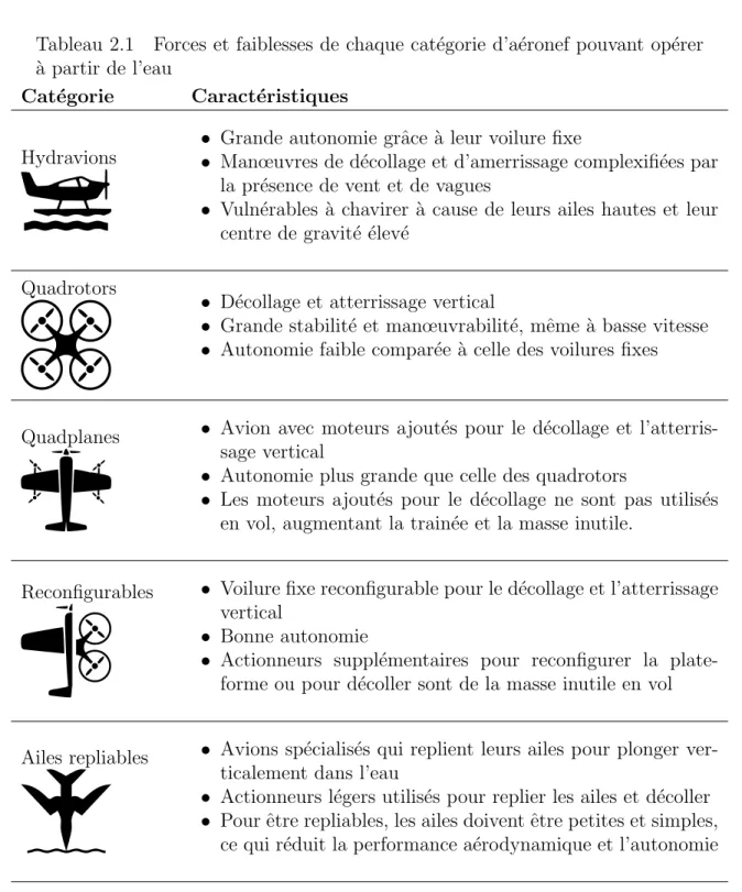
De nombreux UAV sont maintenant capables d’op´erer `a partir de l’eau. Ils peuvent ˆetre re-group´es en cinq grandes cat´egories, chacune poss´edant des caract´eristiques sp´ecifiques : hy-dravions, quadrotors, quadplanes, plateformes reconfigurables, et avions `a ailes repliables. Le tableau 2.1 pr´esente les principales forces et faiblesses de chacune des familles.
`
A la lumi`ere de l’analyse, la conception de toutes les plateformes rel`eve d’un compromis entre une bonne autonomie, la possibilit´e de d´ecollage et d’atterrissage vertical, et la minimisation des composantes ajout´ees non utilis´ees en vol normal. `A titre d’exemple, la transformation d’un drone `a aile fixe incapable de d´ecollage vertical en quadplane n´ecessite l’ajout de quatre groupes propulseurs moteur, h´elice, contrˆoleur. Pour convertir le Bix3 standard [16] en quadplane [6], il faut ajouter 400 g `a un avion pesant `a la base 900 g, et ce sans compter la structure de support requise. Dans une configuration standard, pour la mˆeme augmentation de masse, la batterie pourrait ˆetre tripl´ee, ce qui augmenterait grandement l’autonomie de la plateforme.
Globalement, l’am´elioration d’une caract´eristique entraˆıne in´evitablement la chute d’une autre, et c’est pourquoi aucune des plateformes existantes ne r´eussit `a exceller dans les trois domaines. Cette remarque est d’ailleurs soulign´ee dans une revue des UAV aquatiques existants dans laquelle l’auteur constate qu’aucun UAV compl`etement amphibie couvrant tous ces aspects n’a encore ´et´e d´evelopp´e `a ce jour [49].
La figure 2.1 pr´esente quelques exemples des divers types de plateformes existantes ayant un potentiel pour ˆetre utilis´es comme drones aquatiques. Le compromis entre l’autono-mie, le d´ecollage vertical et la masse ajout´ee est illustr´e par le triangle central. Comme mentionn´e, aucune des plateformes ne r´eussit `a r´epondre aux trois crit`eres. La cible pour un nouveau type de drone aquatique se situe donc au centre du triangle, soit un drone `a d´ecollage et amerrissage vertical poss´edant une grande autonomie et minimisant la masse ajout´ee pour le d´ecollage.
6 CHAPITRE 2. ´ETAT DE L’ART
Tableau 2.1 Forces et faiblesses de chaque cat´egorie d’a´eronef pouvant op´erer `
a partir de l’eau
Cat´egorie Caract´eristiques
Hydravions
• Grande autonomie grˆace `a leur voilure fixe
• Manœuvres de d´ecollage et d’amerrissage complexifi´ees par la pr´esence de vent et de vagues
• Vuln´erables `a chavirer `a cause de leurs ailes hautes et leur centre de gravit´e ´elev´e
Quadrotors
• D´ecollage et atterrissage vertical
• Grande stabilit´e et manœuvrabilit´e, mˆeme `a basse vitesse • Autonomie faible compar´ee `a celle des voilures fixes
Quadplanes • Avion avec moteurs ajout´es pour le d´ecollage et l’atterris-sage vertical
• Autonomie plus grande que celle des quadrotors
• Les moteurs ajout´es pour le d´ecollage ne sont pas utilis´es en vol, augmentant la train´ee et la masse inutile.
Reconfigurables • Voilure fixe reconfigurable pour le d´ecollage et l’atterrissage vertical
• Bonne autonomie
• Actionneurs suppl´ementaires pour reconfigurer la plate-forme ou pour d´ecoller sont de la masse inutile en vol
Ailes repliables • Avions sp´ecialis´es qui replient leurs ailes pour plonger ver-ticalement dans l’eau
• Actionneurs l´egers utilis´es pour replier les ailes et d´ecoller • Pour ˆetre repliables, les ailes doivent ˆetre petites et simples,
7 Autonomie D´ecollage et aterrissage vertical Minimiser masse a jout ´ee GULL 36 [38] Flying fish [10] RQ-15 [44] Sea Scout [30] ULion [3] Quantix [2] QTW UAV [43] SUAV :Q [8]
FireFly6 [4] Falcon Vertigo [12]
Bix3 Quadplane [6]
Water Sampling UAV [29]
Loon Copter [28] Naviator [35] AquaMAV [39] Submersible Concept [48] Gannet UAV [19] Hydravions Reconfigurables
Ailes repliables Quadplanes
Quadrotors
Cible
CHAPITRE 3
M´
ETHODE DE D´
ECOLLAGE ET
D’AMERRIS-SAGE VERTICAL
Avant-propos
Auteurs et affiliation :
– R.A. Peloquin : ´etudiant `a la maˆıtrise, Universit´e de Sherbrooke, D´epartement de g´enie m´ecanique
– D. Thibault : ´etudiant au baccalaur´eat, Universit´e de Sherbrooke, D´epartement de g´enie m´ecanique
– A.L. Desbiens : professeur, Universit´e de Sherbrooke, D´epartement de g´enie m´ecanique Date d’acceptation : 7 novembre 2016
´
Etat de l’acceptation : Version finale publi´ee Revue : IEEE Robotics and Automation Letters R´ef´erence : [33]
Titre fran¸cais : D´eveloppement d’un drone aquatique passif `a d´ecollage et amerris-sage vertical
Contribution au document : Cet article contribue au m´emoire en pr´esentant les m´ethodes de d´ecollage et d’amerrissage verticales d´evelopp´ees pour le drone. Il pr´esente le mod`ele dynamique ´elabor´e pour pr´edire le comportement au d´ecollage ainsi que le mod`ele d’impact ayant permis de dimensionner le drone pour r´esister lors de l’amerrissage en plongeon.
R´esum´e fran¸cais : Dans le but d’augmenter la dur´ee de mission de v´ehicules a´eriens sans pilote, une strat´egie de recharge solaire est envisag´ee en utilisant les lacs comme lieux d’escale et de recharge. Le concept d´evelopp´e est en mesure de d´ecoller et d’amerrir verticalement sur l’eau. Le prototype fabriqu´e consiste en une aile reli´ee `
a un corps central rotatif minimisant les composantes ajout´ees grˆace `a une ma-noeuvre de d´ecollage passive. Un mod`ele dynamique du d´ecollage valid´e par des essais exp´erimentaux sert d’outil de conception. L’amerrissage est ex´ecut´e en plongeant et ne requiert aucun contrˆole complexe ou pliage des ailes. La r´esistance structurelle de l’aile est confirm´ee par l’analyse des acc´el´erations `a l’impact. `A ce sujet, un mod`ele
10 CHAPITRE 3. M ´ETHODE DE D´ECOLLAGE ET D’AMERRISSAGE VERTICAL pr´edictif est d´evelopp´e pour diverses vitesses d’impact. Le prototype final a ex´ecut´e plusieurs d´ecollages r´ep´etables et a r´ealis´e des cycles d’op´erations complets de vol, de plongeon, de flottaison, et de recharge.
3.1. ABSTRACT 11 IEEE Robotics and Automation Letters, Vol.2, No. 2, Avril 2017
Design of a Passive Vertical Takeoff and
Landing Aquatic UAV
Richard-Alexandre Peloquin, Dominik Thibault, Alexis Lussier Desbiens
3.1
Abstract
With the goal of extending Unmanned Aerial Vehicles (UAVs) mission duration, a so-lar recharge strategy is envisioned with lakes as preferred charging and standby areas. The Sherbrooke University Water-Air VEhicle (SUWAVE) concept developed is able to takeoff and land vertically on water. The physical prototype consists in a wing coupled to a rotating center body that minimizes the added components with a passive takeoff maneuver. A dynamic model of takeoff, validated with experimental results, serves as a design tool. The landing is executed by diving, without requiring complex control or wing folding. Structural integrity of the wing is confirmed by investigating the accelerations at impact. A predictive model is developed for various impact velocities. The final prototype has executed multiple repeatable takeoffs and has succeeded in completing full operation cycles of flying, diving, floating and taking off.
Index Terms – Aerial Robotics, Marine Robotics, Biologically-Inspired Robots
3.2
Introduction
Existing UAVs present a trade off between large UAVs that can fly for numerous hours and smaller platforms severely limited in their operating duration. To extend the mission duration of small UAVs, one could use solar panels. However, solar panels are not suffi-cient at small scale to enable continuous flight [27] and landing is required to recharge with minimum energy consumption before flight can be resumed. Numerous teams have created small drones that can land or perch in various locations as vertical walls, wires and moving vehicles [5, 18, 20, 24, 47]. However, finding suitable landing locations in realistic environments, without the use of processing intensive and heavy sensors (e.g., camera, lidar), remains a challenge. In many locations around the world, lakes represent a safe landing area for small UAVs as their locations are well known and their surface is smooth with little to no obstacles. A country like Canada has approximately 9% of its 10 million km2 covered by lakes that see limited human activities [25]. Preliminary calculation based
12 CHAPITRE 3. M ´ETHODE DE D´ECOLLAGE ET D’AMERRISSAGE VERTICAL on hydrographic surveys [22] revealed that a flight range of only 20 km is necessary to traverse Quebec from north to south (1900 km) when traveling from lake to lake.
Seaplanes [10, 30, 34, 44] are often used as aquatic-aerial vehicles but they present chal-lenges as they are scaled down [40]. Takeoff and landing are difficult in waves at smaller size. Also, the high wing and center of mass, along with the decreased wing loading of small UAVs, make them highly sensitive to capsize. Capsizing is an unacceptable failure mode for any long term operations. Aquatic quadrotors [7, 28, 29, 36] are also used and present the advantage of vertical takeoff and landing (VTOL) capabilities. However, their range remains limited when compared to fixed wings. Quadplanes, a hybrid between quadrotors and fixed wing aircrafts, enable both VTOL and long endurance. However, the motors required for vertical thrust are not used in horizontal flight, resulting in dead weight and drag.
From these observations, some functional requirements are proposed and serve as guide-lines for the design of a new type of aquatic UAV :
• float stably on water
• fixed wing for long endurance • large wing area for solar recharge
• ability to right itself in the unlikely even of a capsize
• minimize weight, drag and control complexity from the components added to takeoff and land Solar recharge + flotation Vertical Landing Vertical Takeoff
Figure 3.1 Proposed concept for the vertical takeoff
With regard to these functional requirements, the Sherbrooke University Water-Air VE-hicle (SUWAVE) consists of a reconfigurable flying wing made of two moving parts : the wing and a center body (Fig. 3.1). The center body, containing all the electronics and the motor, is designed to rotate freely about the front of the wing. In flight, both parts are held together by a latch. When the prototype is ready to takeoff, the latch is released. By doing so, the center body pivots under its own weight, while some water seeps in, to
3.3. DYNAMICS OF PASSIVE TAKEOFF 13 reorient the propeller out of the water to a vertical position. The takeoff maneuver occurs passively and requires no control input. Full thrust is applied and the center body emerges from the water, pulling the wing out. Assuming the proper physical characteristics, both parts get aligned within a fraction of a second and automatically latch together into a normal flight configuration. To land, the prototype dives vertically, nose first in the water like a gannet [19, 48].
Figure 3.2 Time lapse of SUWAVE’s vertical takeoff sequence.
This paper addresses essential questions regarding the design of such UAV. Sections 3.3 and 3.4 propose a dynamic model of the passive takeoff and righting maneuvers, and the required physical characteristics for proper operation. Section 3.5 presents an impact model used to compute the accelerations and the stresses in the wing during landing. Finally, section 3.6 and attached video present a functional prototype capable of flying, diving, righting itself, taking off and repeating ad infinitum.
3.3
Dynamics of Passive Takeoff
As mentioned earlier, the success of the takeoff sequence is dependent on many of the physical characteristics of the prototype (e.g., mass properties, motor thrust line). In order to determine which configurations lead to a successful takeoff, a planar dynamic model is developed. As it will be discussed later, a successful takeoff is obtained when the body latches with the wing at a pitch angle between 40 and 60 degrees. The goal of the model
14 CHAPITRE 3. M ´ETHODE DE D´ECOLLAGE ET D’AMERRISSAGE VERTICAL is to simulate the dynamics of a proposed design and determine if the takeoff is successful or not.
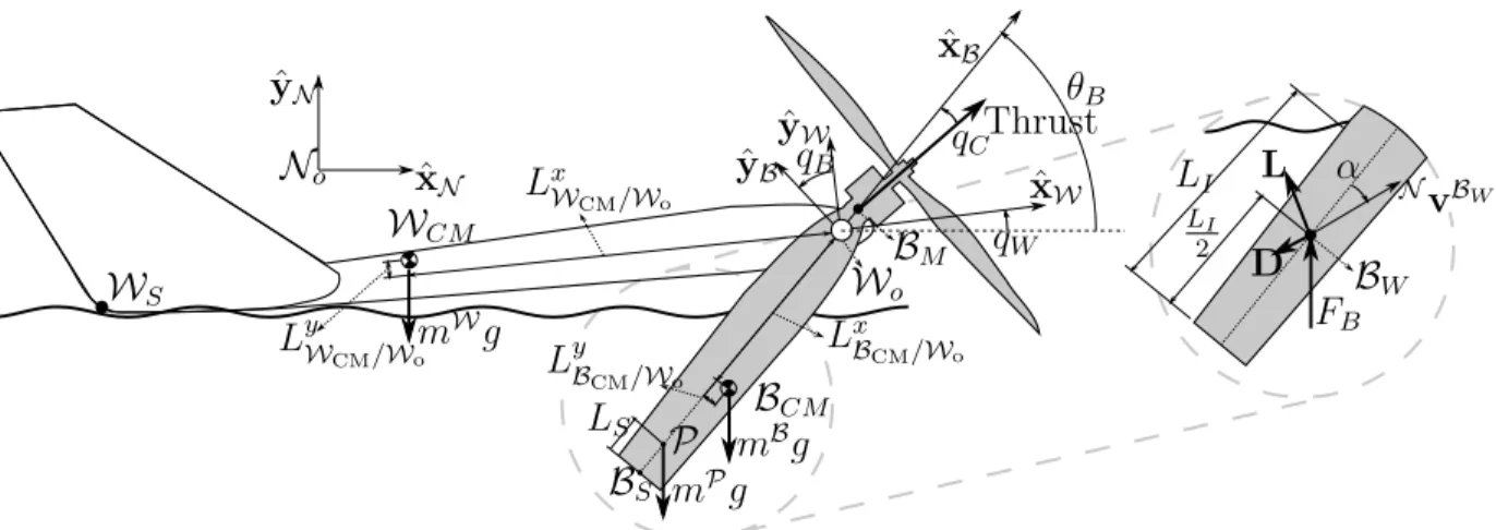
The developed planar model consists of two rigid bodies : the wing and the center body as illustrated in Fig. 3.3. A particle is also added to model the water that seeps inside the body. Four variables are used to describe the configuration of the system : x, y, qW and
qB. These variables respectively represent the position of the pivot and the angles of the
wing and center body. Forces applied on the wing include gravity and contact with the water while the forces applied on the center body include gravity, motor thrust, buoyancy and hydrodynamic forces during the motion through the water. Aerodynamics forces are ignored in the takeoff model. They were initially calculated using a flat plate model [5], but found to represent only 5% of the total gravity forces up to latching. D’Alembert’s method is used to derive compact equations of motion of this system. The following sections give more details on these steps and on the validation of the model.
θB LI LI 2 BW NvBW FB α D L BCM LyB CM/Wo Lx BCM/Wo BS P LS LyW CM/Wo WCM Lx WCM/Wo mWg mBg mPg WS No ˆ yN ˆ xN qW qB BM Wo ˆ xW ˆ yW ˆ xB ˆ yB Thrust qC
Figure 3.3 Diagram of the simplified wing (W), center body (B), reference frames and forces included in the dynamic takeoff model.
3.3.1
Motion
As shown in Fig. 3.3, the model consists of two rigid bodies, the wing and the center body, connected via a frictionless joint. A particle P represents the water present in the center body. For convenience, a reference frame W is attached to the wing and is rotated relative to a Newtonian reference frame N by the angle qW around the unit vector ˆzN. Similarly,
the reference frame B is fixed on the body and is rotated with respect to W by the angle qB about the unit vector ˆzN. The position of the frictionless joint at the origin of the wing
(Wo) with respect to the origin of the Newtonian reference frame (rWo/No) is expressed as
3.3. DYNAMICS OF PASSIVE TAKEOFF 15 body (BCM) and the particle (P) is expressed as :
rWCM/No = rWo/No − Lx WCM/WoxˆW+ L y WCM/WoyˆW (3.1) rBCM/No = rWo/No − Lx BCM/WoxˆB− L y BCM/WoyˆB (3.2) rP/No = rWo/No − Lx P/WoxˆB (3.3)
where parameters LiA/B represent the distances from point A to point B along the unit vector ˆi. Details and values representing the prototype are listed in Table 3.1.
3.3.2
Forces
The various forces modeled are described below : Gravity
Gravity forces are applied at the center of mass of each body (mWg, mBg and mPg). Motor Thrust
The motor thrust is applied at point BM. The thrust line is rotated by an angle qCabout ˆzN
from ˆxB. This variable is important to tune the flight performance and to help the center
body clip to the wing during takeoff. The thrust response to a step command was measured
0 0.2 0.4 0.6 0.8 1 0 2 4 6 8 10 Time (sec) Thrust (N) Measured Thrust Modeled Thrust 1 2
Figure 3.4 Measured static thrust as a function of time, filtered with a 12th order zero phase butterworth filter with a cutoff frequency of 8 Hz, and its corresponding first order fit.
16 CHAPITRE 3. M ´ETHODE DE D´ECOLLAGE ET D’AMERRISSAGE VERTICAL with a force sensor (ATI Mini40 SI-20-1) as illustrated in Fig. 3.4. The initial slope of the measured thrust (Fig. 3.4, zone 1) corresponds to the open loop initialization sequence of the ESC for the sensorless brushless motor. This part is neglected in the simulation and the remaining response is modeled as a first order step response with a time constant of 0.1 sec. The effect of airspeed is approximated as a negative quadratic function, with the measured static thrust as its maximum and the zero crossing at 20 m/sec. As the prototype velocity attains only 1.75 m/sec up to latching, the variation in thrust remains small.
Interaction with water
The interaction of the wing with water is applied at points WS and Wo. The buoyancy
forces are calculated from the submerged volume of the front and back halves of the airplane. At point WS, a viscous force is added in the ˆxN direction to model the drag
created as the submerged section of the wingtip moves through the water during takeoff. This drag force is calculated according to the following equation :
FF = 0.5CDρA⊥˙x2WS (3.4)
where A⊥ corresponds to the component of the submerged wingtip area that is
perpendi-cular to ˆxN, CD is the drag coefficient of a flat plate perpendicular to the flow (i.e., 2), ρ
is the water density, and ˙xWS is the ˆxN velocity of point WS. Both buoyancy and viscous drag forces are set to zero as the points of application leave the surface.
For the center body, the buoyancy force (FB) is modeled as ρgVD, where ρ is water density
and g is gravity. The displaced volume (VD) was measured to be 70% of the center body
immersed volume. Water fills the rest of the body. Assuming a uniform density and a ˆyB
-ˆ
zB cross section (SB) of the center body, the buoyancy varies linearly with the immersed
length LI of the body :
FB = 0.7ρgSBLI (3.5)
This force is exerted on point BW. This point is located halfway through the immersed
length and thus varies as the center body emerges from water (Fig. 3.3). Lift and Drag
For the Reynolds number (i.e. 100, 000) implied in the underwater motion of the center body, a flat plate model adequately approximates the lift L and drag D forces as follows
3.3. DYNAMICS OF PASSIVE TAKEOFF 17 [5] :
L = ρABsin(α) cos(α)|NvBW|(ˆzB×NvBW) (3.6)
D = −ρABsin2(α)|NvBW|NvBW (3.7)
where ρ is the water density, AB is the center body area, as projected on the plane normal
to ˆyB (Fig. 3.3), α is the angle between BW’s velocity in N and the center body
longitu-dinal axis (ˆxB) around −ˆzN. The drag is in a direction opposing BW’s velocity while the
lift is perpendicular, in the positive cross product direction. For simplicity, the point of application of both forces is approximated as point BW.
Added Water
The center body is designed to let water seep inside to enable reorientation by sinking. However, the water takes a certain time to drain during takeoff. This phenomenon is re-presented in the model by adding a particle P with representative mass and position. This added mass mP initially corresponds to 30% of the overall body volume filled with water (i.e., 0.14 kg), as discussed earlier. The mass is approximated to decrease linearly from its initial value to zero in 0.65 seconds, as observed experimentally under a acceleration of 1 g, which is comparable to the peak vertical acceleration of 0.7 g measured during takeoff. During that same period, the particle’s position P is varied linearly from the half body length to the end of the center body.
Latching
For simplicity, the latch at point BS is modeled as a spring-damper (k = 100 N/m,
b = 100 Nsec/m) system that becomes active when qB is less than 2 degrees. The spring
value is chosen to limit the displacement to less than 0.2 deg after latching while the damper value is chosen to prevent rebound.
3.3.3
Equation of Motion (EOM)
In order to obtain the EOM of the system for the state variables x, y, qW and qB,
d’Alem-bert’s method is applied. For a system S of bodies and particles, the resultant forces FS and moments MS/Wo about W
18 CHAPITRE 3. M ´ETHODE DE D´ECOLLAGE ET D’AMERRISSAGE VERTICAL NMS/Wo [23]. Thus : FW+B+P = mW ∗NaWCM + mB ∗NaBCM + ... mP ∗NaP (3.8) M(W+B+P)/Wo = NMW/Wo +NMB/Wo + ... N MP/Wo (3.9) M(B+P)/Wo = NMB/Wo +NMP/Wo (3.10) where N MW/Wo = IW/Wo·NαW+ mWrWCM/Wo ×NaWo N MB/Wo = IB/Wo·NαB+ mBrBCM/Wo ×NaWo N MP/Wo = rP/Wo × mP NaP
The linear accelerations (a) of the various points and the angular accelerations (α) of the various rigid bodies in these equations are obtained by time differentiating the corres-ponding position and orientation of each point and body in the inertial frame N . Scalar equations are produced by extracting the ˆxN and ˆyN components of Eqn. 3.8 and the
ˆ
zN component of Eqns. 3.9 and 3.10. These equations are generated automatically using
MotionGenesisTM and solved with MatlabTM.
3.3.4
Validation
To validate the model, takeoffs with a physical prototype are conducted. The characteris-tics of this prototype, described in section 3.6, are measured and listed in Table 3.1. To compare the results with the model, the position and angles of the wing and the center body are tracked using ViconTM motion capture cameras. As the center body orientation is tracked relative to N , the angle θB corresponding to the angle between ˆxB and ˆxN is
introduced. This angle is related to qB by the equation θB = qW+ qB and will be used for
comparison with the simulation.
An experimental takeoff trajectory is shown in Fig. 3.5. Full thrust is applied during takeoff with a constant elevon trim to compensate the roll inducing motor torque. This better reproduces the planar conditions of the simulation and ensures a mostly planar takeoff trajectory. Indeed, the RMS ratio of the ˆzN linear velocity to the ˆxN − ˆyN velocity is
3.3. DYNAMICS OF PASSIVE TAKEOFF 19
Tableau 3.1 Physical properties of the built prototype
Parameter Variable Value
Wing mass mW 0.263 kg
Wing (W) inertia about Wo IW/Wo 0.00284 kg m2
WCM position from Wo along ˆxW LxWCM/Wo 0.202 m WCM position from Wo along ˆyW LyW
CM/Wo 0.002 m
Body mass mB 0.321 kg
Body (B) inertia about Wo IB/Wo 0.0021 kg m2
BCM position from Wo along ˆxB LxB
CM/Wo 0.049 m BCM position from Wo along ˆyB LyBCM/Wo −0.007 m
Motor angle from ˆxB along ˆzN qC −5.12 deg
BM position from Wo along ˆxB LBM/Wo 0.018 m BS position from Wo along ˆxB LBS/Wo 0.16 m Water contact damping coefficient b 3.75 Nsec/m Water contact spring coefficient k 890 N/m
-0.5 0 0.5 -1.5 -1 -0.5 0 0.5 0 0.5 1 ˆ xN ˆ zN ˆyN
Figure 3.5 The 3D trajectory of the prototype during takeoff as captured by Vicon is mostly planar. Frames are spaced by 0.12 sec.
20 CHAPITRE 3. M ´ETHODE DE D´ECOLLAGE ET D’AMERRISSAGE VERTICAL 0 1 2 3 0 0.5 1 1.5 ˆyN (m) ˆ xN (m) Sim Exp 1 Exp 2 Exp 3
Figure 3.6 Comparison of the trajectory of point Wo in simulation and during
three distinct experimental takeoffs for time varying from 0 to 1 sec.
0 0.5 1 1.5 0 20 40 60 80 100 Angle (deg) t (sec) Sim Exp 1 Exp 2 Exp 3 θB qW latching
Figure 3.7 Time behavior of angles qW and θB. Note that the bracket latches
3.3. DYNAMICS OF PASSIVE TAKEOFF 21 The results of the simulation are compared to experimental takeoffs in Figs. 3.6-3.7. Fig. 3.6 shows the trajectory of point Wo for three experimental takeoffs and for the corresponding
dynamic simulation. The time behavior of variables qW and θB is illustrated in Fig. 3.7.
For all these tests, the wing starts flat on the water, with the propeller upward. During takeoff, the wing pitches up and latches with the body around 0.4 sec. After latching, the angle of the system naturally decreases toward zero for normal flight. Although the agreement between the simulation and the experimental results is good, particularly for latching angle prediction, small differences exist. The simulation starts diverging after one second as the speed increases and the aerodynamic forces not included in the simulation become more important. Predicted and measured angles prior to latching also differ due to the added inertia and sloshing from the water within the center body. Future versions of the prototype will be designed to better evacuate the water.
3.3.5
Design
It was experimentally observed that successful takeoffs require the latching between the wing and the center body to occur within a certain range of pitch. Indeed, if latching occurs at a small pitch angle, the front of the prototype usually dives into the water. Similarly, latching at a large pitch angle causes the prototype to flip backward and crash. Both of these scenarios are illustrated in Fig. 3.8. To determine the influence of the various design parameters one to another, several simulations with varying pairs of parameters were realized. The takeoff were considered as successful when the center body latches with the wing at a pitch angle between 40 and 60 degrees.
135 deg latch Start Finish Finish 31 deg latch 54 deg latch Finish Flip takeoff Successful takeoff Dive takeoff
Figure 3.8 Simulation of three takeoffs using the parameters of Table 3.1. The value of the motor angle qC is changed between −0.5 deg (flip) and −9 deg
(dive). Both cases latch at an angle outside of the range of 40 to 60 degrees. Refer to Fig. 3.9 for the acceptable range of qC.
22 CHAPITRE 3. M ´ETHODE DE D´ECOLLAGE ET D’AMERRISSAGE VERTICAL 0 0.02 0.04 0.06 0.08 0.1 1 1.5 2 2.5 3x 10⁻³ lBcmX 0.2 0.25 0.3 0.35 0.4 -10 -8 -6 -4 -2 0 mB qc 0 0.02 0.04 0.06 0.08 0.1 -0.01 -0.008 -0.006 -0.004 -0.002 0 lBcmX 0 0.02 0.04 0.06 0.08 0.1 0.1 0.15 0.2 0.25 lBcmX lA cm X 0 0.02 0.04 0.06 0.08 0.1 -10 -8 -6 -4 -2 0 lBcmX qc -0.01 -0.008 -0.006 -0.004 -0.002 0 -10 -8 -6 -4 -2 0 lBcmY qc 0 0.02 0.04 0.06 0.08 0.1 0.2 0.25 0.3 0.35 0.4 lBcmX 0.15 0.2 0.25 0.3 0.35 0.2 0.25 0.3 0.35 0.4 mA m B mB lBcmY Ibzz
Figure 3.9 Influence of each parameters on the success of takeoff. The light gray zone corresponds to a latching angle over 60 degrees while the dark gray zone corresponds to a latching angle below 40 degrees. The white area represents a successful takeoff. Units are expressed in the SI system and degrees. The black dot locates the characteristics of the physical prototype.
3.4. RIGHTING AFTER CAPSIZE 23 From this criterion, Fig. 3.9 shows the results of the simulations for each pair of parameters. A successful takeoff occurs for pairs of parameters located within the white area of the graphs. From these graphs, the influence of each parameter is demonstrated and tendencies can be expressed. In general, a negative moment around ˆzB must be created on the center
body to make it latch. However, too much moment will make the wing dive. More negative values of qC and LyBCM/Wo, increasing m
B, or decreasing IB/Wo and Lx
BCM/Wo all create a larger negative moment. The results also show that most parameters are linked together. For instance, if mB is increased, the absolute value of qC should be more negative to
ensure a successful takeoff. Some parameters (e.g., mW), however, have limited impact on the takeoff, as it is shown by the horizontal white area in the bottom-right graph.
3.4
Righting after capsize
Interestingly, optimizing the system for successful takeoff also improves the ability of the prototype to right itself in the unlikely chance of capsizing. Indeed, adjusting the parameters for successful right-side up takeoff encourages late latching when taking off from a capsized position and thus flipping. Fig. 3.10 shows a simulated example of the righting process using the same takeoff model presented in section 3.3. The thrust is cut when the wing is vertical to ensure a smooth landing.
0 0.2 0.4 0.6 0.8 -0.2 0 0.2 0.4 ˆ xN (m) ˆyN (m) Finish Start
Figure 3.10 Simulation results of the wing righting. Refer to supplementary material to see experimental results.
24 CHAPITRE 3. M ´ETHODE DE D´ECOLLAGE ET D’AMERRISSAGE VERTICAL
3.5
Dive Landing
As described before, diving is investigated as a preferred method for vertical landing. This landing strategy reduces the approach distance and increases the landing precision, allowing the use of smaller lakes surrounded by tall obstacles. This method also eliminates the approach phase in close proximity to the water during landing, which makes the prototype less sensitive to being capsized by wind gusts or waves. However, this type of landing is still uncommon and the impact forces and resulting structural stresses must be considered.
3.5.1
Impact Modeling
To estimate the magnitude of the forces exerted on the wing during landing, experimental dive tests are first conducted. A prototype wing is released from various heights in the water. It is guided along its descent by wires to ensure vertical trajectories with zero angle of attack. The wing is fitted with a GCDCTM X250-2 accelerometer (3 axes, 14 bits
resolution, ±250 g, 512 Hz). Fig. 3.11 presents the registered acceleration for different impact velocities. Off axis (i.e., x, y) accelerations are shown to be around 15% of the maximal z acceleration. Dives with negligible angle of attack reduce the total acceleration and a simple flight controller can ensure that this condition is satisfied.
0 0.1 0.2 0.3 -5 0 5 10 15 Time (sec) Acceleration in x (g) 9.6 m/sec 8.9 m/sec 7.9 m/sec 6.2 m/sec ax ay, az acceleration for ˙x = 8.9 m/sec A B
Figure 3.11 Measured x accelerations for various impact velocities. The acce-lerations in y and z are illustrated to show that the impact occurs mainly in x.
3.5. DIVE LANDING 25 The recorded accelerations show two behaviors : a high peak acceleration (point A) varying with the impact velocity and a mostly constant plateau around point B. To model the behavior of the wing during its dive, a one dimensional model is used with both a velocity dependent term [45], a submerged volume term and gravity :
m¨x = CBρgVS+ CVAf˙x2− mg (3.11)
where CB and CV are constant coefficients related to the submerged volume and the
velocity respectively. They include other effects (e.g., added mass, air entrainment) and are fixed for a wing geometry. The parameters ρ, VS and Af are the water density, the
submerged volume and the frontal area. The wing is modeled as a simple constant thickness prism as illustrated in Fig. 3.12. The VS and Af terms are function of the position x,
the thickness of the wing e and the sweep angle φ according to VS = e tan(φ)x2 and
Af = 2e tan(φ)x. These function can be combined with Eqn. 3.11 as :
m¨x = CBρge tan(φ)x2+ 2CVe tan(φ)x ˙x2− mg (3.12)
Af e VS φ x ˙x Water z y z y
Figure 3.12 Representation of the simplified wing, notice the submerged vo-lume and the frontal area
To identify parameters CB and CV, experimental results are compared to the model.
Equation 3.12 can be solved at point C in Fig. 3.13, where ˙x = 0 (calculated by integrating the acceleration from the initial impact speed), to find the value of CB. The value of CV
can then be tuned manually so that the peak of acceleration at point A corresponds to the measurements. Fig. 3.13 shows one experimental dive along with the results of a simulation, including each component of the total acceleration. Fig. 3.14 shows that the same parameters are valid for a variety of impact speeds, either dominated by buoyancy or velocity related effects. This correlation suggests that impact forces of future geometry
26 CHAPITRE 3. M ´ETHODE DE D´ECOLLAGE ET D’AMERRISSAGE VERTICAL could be predicted with a single experimental drop to calibrate CBand CV to the platform.
Finally, for an impact velocity of 10 m/sec, the maximal depth reached is 0.6 m implying that the prototype could land in shallow water.
0 0.1 0.2 0.3 0.4 -5 0 5 10 15 Time (s) Acceleration (g) Measured Total Sim CVAf ˙x2 CBρgVS A C ˙x = 0
Figure 3.13 Impact model as fitted with the experimental results. Individual components of the acceleration are also illustrated (CB = 0.6, CV = 50).
0 2 4 6 8 10 0 5 10 15 20
Impact Velocity (m/sec)
P eak Acceleration (g) Simulation Experiments
Figure 3.14 Graph of peak acceleration vs impact velocity. The parametric mo-del (Eqn. 3.12, CB = 0.6, CV = 50) is compared with the experimental results.
Mean results are represented by the ∗ symbol while the error bars represent the maximum and minimum peak accelerations obtained for five impacts at that velocity.
3.5. DIVE LANDING 27
3.5.2
Structural Sizing
The knowledge of impact acceleration allows the validating of the structural feasibility of a dive landing. The prototype is modeled as a constant section foam beam representing a half wing (Fig. 3.15). To assume a worst case stress, the carbon fiber spar is not considered in the calculations. The beam is fixed on one end and the accelerations are applied over the wingspan as a uniformly distributed inertial load of magnitude m¨xmax/2l, where ¨xmax
corresponds to the maximum acceleration during impact. A reaction force is solely applied on the nose of the prototype (at the fixed end). Overall, this model is conservative as this reaction force is really applied on a broader surface on the wing while most of the mass is located in the center body instead of being uniformly distributed along the wing.
e c R l M = 14ml¨xmax I = 23ec3 m¨xmax 2l
Figure 3.15 Representation of a half wing for stress analysis. The equations for the moment and the inertia are expressed as a function of geometry.
From simple beam theory, the maximum stress σ occurs at the fixture and corresponds to σ = M c/I. By replacing the moment M and the inertia I by their values, the stress becomes :
σmax=
3ml¨xmax
8ec2 (3.13)
The resistance of the polystyrene foam was estimated at 0.21 MPa [42]. For an impact at 10 m/sec, which corresponds roughly to the cruising speed of the prototype, the peak acceleration is 15 g. This produces a stress of 0.02 MPa, resulting in a margin of safety of 10. Based on the results, it appears that the small frontal area, the profiled shape of the wing and the stiff wing geometry are all contributing to make diving a structurally safe way of landing. As validated on the prototype, this method does not necessitate adding reinforcements, supplementary structure elements or wing folding.
28 CHAPITRE 3. M´ETHODE DE D´ECOLLAGE ET D’AMERRISSAGE VERTICAL
3.6
Implementation and Results
Using the takeoff dynamic model and XFLR5 [46], a physical configuration was chosen for passive takeoff and stable flight. SUWAVE is a flying wing (Fig. 3.16) made of polystyrene reinforced with a carbon fiber spar. Two winglets also made of polystyrene are fixed at each end. Beside their normal use in flight, the winglets also keep the wing facing upwind and ready for takeoff while resting on the water. The underside of the wing lays directly in contact with the water so that it remains unperturbed by wind gusts.
Winglets Carbon spar Wing Center body Motor Pivot
Figure 3.16 Representation of the various component of SUWAVE.
The prototype uses a single brushless motor with a 11× 6 folding propeller, an 18 A ESC and a 3C 1000 mAh LiPo battery. A receiver and two servomotors control the elevons. A NACA M3 airfoil is chosen for its large thickness ratio, providing space for the electronics. The final design has a 1 m wingspan with a 33 degrees sweep angle. The root chord is 320 mm long with a taper ratio of 0.5.
The center body is made of printed PLA with carbon inserts to hold the components in place and stiffen the structure. A spring loaded pin automatically latches the body with the wing as both bodies become aligned. To release the center body for takeoff, the pin is retracted by a lightweight shape memory alloy wire. A piece of foam added under the center body helps maintaining the propeller upright prior to takeoff. The pivot consists of a carbon tube inserted through the wing and the center body. Fig. 3.17 presents a cutaway view of the center body while Table 3.2 shows a detailed mass budget.
With SUWAVE, numerous takeoff, dive and righting cycles were performed, as illustrated in Fig. 3.2 and demonstrated in the supplementary video. The prototype performs well
3.6. IMPLEMENTATION AND RESULTS 29 Carbon inserts Battery ESC Pin
RC switch Receiver Shape memory alloy Carbon pivot
Connector
Foam
Figure 3.17 Cutaway view of the center body. The position of the center of mass is shown.
Tableau 3.2 Mass budget of the prototype
Number Component Mass (g)
1 Foam wing + carbon spar + winglets 231
2 Carbon pivot + wing latch 14
3 2 GS-9018 servos 18
Subtotal : Wing 263
4 TurnigyTM 11.1 V 3C 1000 mAh Battery 85
5 TurnigyTM Plush 18 A ESC 29
6 SpektrumTM AR610 Receiver 26
7 EMaxTM CF2822 Motor 39
8 11 × 6 folding propeller 38
9 RC switch + SMA wire + pin 11
10 Battery connector 9
11 Foam 3
12 PLA printed body + carbon inserts 82 Subtotal : Center body 321
Total weight 584
but remains sensitive to wind gusts at takeoff, which sometimes prevent the center body from latching.
It is interesting to compare the added mass required by this prototype to that of a quad-plane. The components added for takeoff on this prototype (items 2, 9, 10, and 11) weight about 37 g without much optimization. Part of the center body PLA structure should also be added to that total, although the exact fraction is hard to determine because some structural element must be present to support the electronics, even for standard takeoff. The added weight for the presented concept is thus estimated to be between 37 and 119 g. For comparison, converting this flying wing into a quadplane would require the addition of motors, ESC, and fixed propellers with a combined thrust-to-weight (T/W) ratio larger
30 CHAPITRE 3. M ´ETHODE DE D´ECOLLAGE ET D’AMERRISSAGE VERTICAL than one. Assuming components with a similar thrust density as used on this prototype (T/W = 1.56), the added mass of extra motors, ESC and propeller would be between 68 (items 5 and 7) and 106 g (items 5, 7 and 8), without considering the structural elements and wiring of the added propulsion system. The exact number depends on the propeller used. More careful analysis are required, but the concept presented in this paper seems to represent a viable alternative to aquatic quadplanes.
3.7
Conclusions and Future Work
This paper presents the modeling, design and fabrication of SUWAVE, a vertical takeoff and landing aquatic UAV. The prototype built is capable of a repeated cycles of flying, diving, righting and takeoff. The takeoff sequence occurs passively and a dynamic model has been developed to serve as a design tool. The influence of relevant parameters such as mass properties and motor angle have been investigated. The prototype is able to self right itself and is robust to wind gusts and waves while floating.
A diving approach has also been investigated for landing and a model predicting the accelerations for various impact velocities has been developed. This model is valid for various impact velocities, can be calibrated quickly from a single dive experiment and provide load cases for the structural design of the wing. By using the geometry of the wing advantageously, diving enables landing in small lakes surrounded by tall obstacles, without the need of reinforcements or wing folding.
The next steps will involve detail optimization and FEA analysis of the airframe to better characterize the additional mass required by this concept. Autonomous mission control will also be implemented for long duration operation and standby. Finally, solar panels will also be added on the wing to allow long endurance missions and lake-to-lake travel.
CHAPITRE 4
CONCLUSION
Ce projet avait pour but de d´eterminer s’il ´etait possible de d´evelopper un nouveau type de drone capable d’ex´ecuter de longues missions et permettant l’acc`es aux zones restreintes aux drones `a voilure fixe conventionnels. Concr`etement, il a permis la conception et la fabrication d’un drone aquatique fonctionnel. La strat´egie passive d´evelopp´ee permet le d´ecollage vertical de la plateforme, tout en minimisant l’ajout de masse. Sa construction robuste permet l’amerrissage en plongeon. Le fonctionnement de l’aile volante a ´et´e valid´e dans des conditions r´eelles, le drone r´eussissant plusieurs cycles de mission complets suc-cessifs. La strat´egie de mission choisie rend possible le parcours de longues distances. Le d´ecollage vertical et le plongeon donne acc`es `a plusieurs nouveaux lieux d’op´eration o`u les avions conventionnels ne peuvent se rendre par manque d’espace.
En plus de la plateforme physique, le projet a ´egalement permis de d´evelopper des mod`eles de simulation permettant de bien comprendre les deux phases les plus critiques de la mis-sion, soit le d´ecollage et l’amerrissage. Pour permettre de concevoir le drone, un mod`ele de simulation dynamique du drone au d´ecollage a ´et´e cr´e´e. Il permet de pr´edire son compor-tement lorsque ses propri´et´es physiques sont chang´ees. L’autre phase de mission ´etudi´ee est l’amerrissage. Ici aussi, mod`ele de simulation de l’impact avec l’eau permet de cal-culer `a l’avance les acc´el´erations subies par le drone selon sa vitesse d’entr´ee dans l’eau. Ce mod`ele est particuli`erement utile pour ´evaluer la r´esistance du drone lors de sa phase de conception. Le mod`ele d´evelopp´e pourrait ˆetre utilis´e pour pr´edire les chargements de diff´erentes plateformes dans l’eau.
Les prochaines ´etapes pour le d´eveloppement d’un drone aquatique pouvant ˆetre utilis´e dans des missions de longue dur´ee serait d’y int´egrer des panneaux solaires ´etanches. Ceci permettrait d’augmenter grandement son autonomie, diversifiant davantage le nombre de missions possibles. ´Egalement, l’ajout d’un contrˆoleur de vol autonome permettrait de se d´epartir du besoin d’un pilote exp´eriment´e. De ce cˆot´e, plusieurs d´efis concernant la gestion du cycle de mission et la d´erive durant la nuit demeurent. `A plus long terme, le drone sera intelligent, d´ecidant lui-mˆeme quand d´ecoller et o`u se poser pour se recharger. De plus, la d´erive du drone devra ˆetre consid´erer pour ´eviter de s’´echouer et de rester coinc´e durant la phase de recharge. Pour cela, diverses strat´egies de repositionnement ou l’ajout de dispositifs r´eduisant cette d´erive pourraient ˆetre int´egr´ees.
LISTE DES R´
EF´
ERENCES
[1] AeroVironment (2017). WASP AE. https://www.avinc.com/uas/view/wasp (page consult´ee le 2017-10-26).
[2] AeroVironment (2017). Quantix. https://www.avinc.com/media_center/ commercial-information-solutions/quantix (page consult´ee le 2017-11-27). [3] Ang, K. Z., Cui, J., Pang, T., Li, K., Wang, K., Ke, Y. et Chen, B. M. (2014).
Development of an unmanned tail-sitter with reconfigurable wings : U-Lion. Dans 11th IEEE International Conference on Control & Automation (ICCA), IEEE. p. 750–755. [4] BirdsEyeView Aerobotics (2017). FireFLY6 PRO. https://www.birdseyeview.
aero/products/firefly6 (page consult´ee le 2017-11-27).
[5] Cory, R. et Tedrake, R. (2008). Experiments in fixed-wing UAV perching. Dans Pro-ceedings of the AIAA Guidance, Navigation, and Control Conference, AIAA Reston, VA. p. 1–12.
[6] Covey, Gregory (2016). Bix3 QuadPlane Flight 1. https://vimeo.com/176927403 (page consult´ee le 2017-11-23).
[7] Drews, P. L., Neto, A. A. et Campos, M. F. (2014). Hybrid unmanned aerial under-water vehicle : Modeling and simulation. Dans 2014 IEEE/RSJ International Conf. on Intelligent Robots and Systems. p. 4637–4642.
[8] D’Sa, R., Jenson, D., Henderson, T., Kilian, J., Schulz, B., Calvert, M., Heller, T. et Papanikolopoulos, N. (2016). SUAV : Q-An improved design for a transformable solar-powered UAV. Dans Intelligent Robots and Systems (IROS), 2016 IEEE/RSJ International Conference on, IEEE. p. 1609–1615.
[9] Erdelj, M. et Natalizio, E. (2016). UAV-assisted disaster management : Applications and open issues. Dans Computing, Networking and Communications (ICNC), 2016 International Conference on, IEEE. p. 1–5.
[10] Eubank, R. D. (2012). Autonomous flight, fault, and energy management of the flying fish solar-powered seaplane. Doctoral thesis, The University of Michigan, Ann Arbor, USA, 219 p.
[11] Filippone, A. (2006). Flight performance of fixed and rotary wing aircraft. Elsevier. [12] Flyingwings (2015). Falcon Vertigo Hybrid VTOL RTF. http://flyingwings.co.
uk/venturi-fpv-wing-192.html (page consult´ee le 2017-11-27).
[13] General Atomics Aeronautical (2017). Predator B RPA. http://www.ga-asi.com/ predator-b (page consult´ee le 2017-10-26).
34 LISTE DES R´EF´ERENCES [14] Girard, A. R., Howell, A. S. et Hedrick, J. K. (2004). Border patrol and surveillance missions using multiple unmanned air vehicles. Dans Decision and Control, 2004. CDC. 43rd IEEE Conference on, IEEE. Volume 1. p. 620–625.
[15] Grenzd¨orffer, G., Engel, A. et Teichert, B. (2008). The photogrammetric potential of low-cost uavs in forestry and agriculture. The International Archives of the Photo-grammetry, Remote Sensing and Spatial Information Sciences, volume 31, num´ero B3, p. 1207–1214.
[16] Hobby King (2017). Hobby King Bix3 Trainer/FPV EPO 1550mm Mode 2 (ready-To-Fly). https://hobbyking.com/en_us/ hobbykingtm-bix3-trainer-fpv-epo-1550mm-mode-2-ready-to-fly.html? ___store=en_us (page consult´ee le 2017-12-11).
[17] Israel, M. (2011). A UAV-based roe deer fawn detection system. International Ar-chives of Photogrammetry and Remote Sensing, volume 38, p. 1–5.
[18] Kovaˇc, M., Germann, J., H¨urzeler, C., Siegwart, R. Y. et Floreano, D. (2009). A perching mechanism for micro aerial vehicles. Journal of Micro-Nano Mechatronics, volume 5, num´ero 3-4, p. 77–91.
[19] Liang, J., Yao, G., Wang, T., Yang, X., Zhao, W., Song, G. et Zhang, Y. (2014). Wing load investigation of the plunge-diving locomotion of a gannet morus inspired submersible aircraft. Science China Technological Sciences, volume 57, num´ero 2, p. 390–402.
[20] Lussier Desbiens, A., Asbeck, A. T. et Cutkosky, M. R. (2011). Landing, perching and taking off from vertical surfaces. The International Journal of Robotics Research, volume 30, num´ero 3, p. 355–370.
[21] Mehanovic, D., Bass, J., Courteau, T., Rancourt, D. et Desbiens, A. L. (2017). Auto-nomous Thrust-Assisted Perching of a Fixed-Wing UAV on Vertical Surfaces. Dans Conference on Biomimetic and Biohybrid Systems, Springer. p. 302–314.
[22] MERN Quebec (2010). Quebec surface hydrography. http://mern.gouv.qc.ca/ territoire/portrait/portrait-donnees-mille.jsp (page consult´ee le 2016-09-10).
[23] Mitiguy, P. (2014). Advanced Dynamics & Motion Simulation, 1re ´edition. Prodigy
Press, 563 p.
[24] Moore, J. et Tedrake, R. (2009). Powerline perching with a fixed-wing UAV. Dans Proceedings of the AIAA Infotech@ Aerospace Conf., Seattle, AIAA Seattle, WA. p. 1–16.
[25] Natural Resources Canada (2005). Land and freshwater area, by province and territory. http://www.statcan.gc.ca/tables-tableaux/sum-som/l01/cst01/ phys01-eng.htm (page consult´ee le 2017-09-10).
LISTE DES R´EF´ERENCES 35 [26] Northrop Grumman (2017). Global Hawk. http://www.northropgrumman.com/
Capabilities/GlobalHawk/Pages/default.aspx (page consult´ee le 2017-10-26). [27] Noth, A., Siegwart, R. et Engel, W. (2008). Design of solar powered airplanes for
continuous flight. Doctoral thesis, ETH, Zurich, Switzerland, 170 p.
[28] Oakland University Embedded Systems Research Lab (2016). Loon Copter. https: //sites.google.com/a/oakland.edu/oar/ (page consult´ee le 2017-10-26).
[29] Ore, J.-P., Elbaum, S., Burgin, A. et Detweiler, C. (2015). Autonomous aerial water sampling. Journal of Field Robotics, volume 32, num´ero 8, p. 1095–1113.
[30] Oregon Iron Works (2006). Sea Scout Unmanned Tactical Seaplane OffersIncrea-sed Mission Flexibility and Utility. https://www.scribd.com/document/40874493/ Seascout (page consult´ee le 2017-12-06).
[31] Parkinson, J. B. (1955). NACA Model Investigations of Seaplanes in Waves.
[32] Parrot (2017). Parrot DISCO. https://www.parrot.com/ca/drones/ parrot-disco#parrot-disco (page consult´ee le 2017-10-26).
[33] Peloquin, R.-A., Thibault, D. et Desbiens, A. L. (2017). Design of a Passive Vertical Takeoff and Landing Aquatic UAV. IEEE Robotics and Automation Letters, volume 2, num´ero 2, p. 381–388.
[34] Pisanich, G. et Morris, S. (2002). Fielding an amphibious uav : development, results, and lessons learned. Dans Digital Avionics Systems Conference, 2002. Proceedings. The 21st, IEEE. Volume 2. p. 8C4–1.
[35] Rutgers University (2015). New Underwater Drone Flies AND Swims. http://soe. rutgers.edu/naviator (page consult´ee le 2017-11-27).
[36] Schwarzbach, M., Laiacker, M., Mulero-P´azm´any, M. et Kondak, K. (2014). Remote water sampling using flying robots. Dans Unmanned Aircraft Systems (ICUAS), 2014 International Conference on, IEEE. p. 72–76.
[37] senseFly (2017). eBee : senseFly SA. https://www.sensefly.com/drones/ebee. html (page consult´ee le 2017-10-26).
[38] Sherer, Kyle (2008). GULL 36 Seaplane UAV begins English Channel flights. https: //newatlas.com/gull-36-uav/9457/ (page consult´ee le 2017-11-27).
[39] Siddall, R., Ancel, A. O. et Kovaˇc, M. (2017). Wind and water tunnel testing of a morphing aquatic micro air vehicle. Interface Focus, volume 7, num´ero 1, p. 20160085. [40] Siddall, R. et Kovaˇc, M. (2014). Launching the AquaMAV : bioinspired design for aerial–aquatic robotic platforms. Bioinspiration & biomimetics, volume 9, num´ero 3, p. 031001.
36 LISTE DES R´EF´ERENCES [41] Tang, L. et Shao, G. (2015). Drone remote sensing for forestry research and practices.
Journal of Forestry Research, volume 26, num´ero 4, p. 791–797.
[42] The DOW Chemical Company (2016). STYROFOAM Polystyrene Foam Insulation. http://www.dow.com/elibrary (page consult´ee le 2016-09-10).
[43] Tran, A. T., Sakamoto, N., Sato, M. et Muraoka, K. (2017). Control augmentation system design for quad-tilt-wing unmanned aerial vehicle via robust output regula-tion method. IEEE Transacregula-tions on Aerospace and Electronic Systems, volume 53, num´ero 1, p. 357–369.
[44] University National Oceanographic Laboratory System (2007). Brief introduction on DRS RQ-15 Neptune. http://www.unols.org/sites/default/files/Neptune% 20UAV.pdf (page consult´ee le 2017-10-26).
[45] Von Karman, T. (1929). The impact on seaplane floats during landing.
[46] XFLR5 (2017). XFLR5. http://www.xflr5.com/ (page consult´ee le 2017-12-06). [47] Xu, G., Zhang, Y., Ji, S., Cheng, Y. et Tian, Y. (2009). Research on computer
vision-based for UAV autonomous landing on a ship. Pattern Recognition Letters, volume 30, num´ero 6, p. 600–605.
[48] Yang, X., Liang, J., Wang, T., Yao, G., Zhao, W. et Shen, Q. (2013). Submersible unmanned aerial vehicle concept design study. Dans 2013 Aviation Technology, Inte-gration, and Operations Conference. p. 4422.
[49] Yang, X., Wang, T., Liang, J., Yao, G. et Liu, M. (2015). Survey on the novel hybrid aquatic–aerial amphibious aircraft : Aquatic unmanned aerial vehicle (AquaUAV). Progress in Aerospace Sciences, volume 74, p. 131–151.