This is an author-deposited version published in :
http://oatao.univ-toulouse.fr/
Eprints ID : 9269
To link to this article : DOI:10.1109/MIE.2012.2221355
URL : http://dx.doi.org/10.1109/MIE.2012.2221355
O
pen
A
rchive
T
OULOUSE
A
rchive
O
uverte (
OATAO
)
OATAO is an open access repository that collects the work of Toulouse researchers and
makes it freely available over the web where possible.
To cite this version : Roboam, Xavier and Sareni, Bruno and
Andrade, André De More Electricity in the Air: Toward Optimized
Electrical Networks Embedded in More-Electrical Aircraft. (2012)
IEEE Industrial Electronics Magazine, vol. 6 (n ° 4). pp. 6-17.
ISSN 1932-4529
XAVIER ROBOAM, BRUNO SARENI, and ANDRÉ DE ANDRADE
long with the main trends and future challenges of electrical networks embedded in more-electrical aircraft, this article also focuses on optimization efforts in the field of industrial electronics and energy conversion. Optimization can be achieved by the means of expertise or from classical analysis methods, especially those based on simulations. However, novel approaches based on optimization algorithms, so-called integrated design by optimization, are becoming increasingly mature and will become particularly powerful if subsequent efforts are made in terms of modeling for design. In the first part, the current context and new standards of the more-electrical aircraft are summarized. The second part deals with the new trends and challenges
A
Toward Optimized Electrical Networks
Embedded in More-Electrical Aircraft
© DIGI
T
AL VISION
of more electrical aircraft, with an emphasis on reversible and hybrid high-voltage dc networks includ-ing new storage devices. However, this discussion will mainly focus on systems optimization. Methodologi-cal orientations toward integrated optimal design are discussed with representative examples, such as for an environmental conditioning system (ECS).
Current Context and Standards The air traffic market is estimated to grow at 5% per year until 2020, in the context of strong competition between Europe and the United States, while new providers of commercial aircraft will appear in North America and Asia. The aerospace industry will have to face both economical and environ-mental issues. For example, civil avia-tion emitted some 2% of man-made CO2 emissions into the atmosphere in 2008 [1]. It is often claimed that 1 kg saved on each flight could save roughly 1,700 t of fuel and 5,400 t of CO2 per year for all air traffic. Further-more, a decrease in mass would also be profitable in terms of cost: each kilogram of systems costs approxi-mately US$1,000.
Furthermore, mass saving would be profitable: a gain of 1 kg on the sys-tems increases the price by approxi-mately US$1,000.
Thus, the aircraft manufacturing industry is placing greater empha-sis on the use of technologies that can influence both the overall costs (design, operation, and maintenance) and fuel consumption. In addition to the aerodynamic structure and the engine optimization, equipment systems will also play a major role, especially in reducing operation costs with minimum maintenance and maxi-mum availability.
More Electrical Systems and Power Needs
In this context, the rationalization of power sources has led engineers to an electrical aircraft design in which conventional devices are replaced by electrical systems [2]. This trend is de-picted in Figure 1, which displays the
evolution of electrical power needs. So far, a conventional aircraft has four different integrated energy vectors (see Figure 2):
■ pneumatic power for air condition-ing, the wing ice protection system (WIPS) and engine start-up
■ electric power for commercial loads and avionic systems
■ hydraulic power for pumps and flight control actuators
■ mechanical power to drive hydrau-lic or fuel pumps directly from the engine gearbox.
FIGURE 2 – Current architecture with four different energy vectors. Hydraulic Power
Pneumatic Power Electrical Power
Fuel Pump Fans
Commercial Loads Cabin De-Icing
Mechanical Power
FIGURE 1 – Evolution of electrical power needs.
0 100 200 300 400 500 600 P (KVA) 1962 1966 1969 1987 1993 2004 Year
Caravelle B737 Concorde A320 A330 A380
1,000
2010 B787
Furthermore, a decrease in mass would also be
profitable in terms of cost: each kilogram of systems
costs approximately US$1,000.
From Fixed to Variable Frequency Generation
The first generation of electrical networks was equipped with fixed-frequency (115/200 VAC 400 Hz) integrated drive generators as on the A320, A330, and A340. In order to simplify the constant-speed mechani-cal gearbox, the variable- frequency generators are preferred, as on the A380 and on the next A350, for which the voltage standard is doubled (230/400 VAC) with respect to the in-crease in electrical power needs. Cer-tain prospective solutions for power generation have also been studied. For example, in the framework of the European Commission’s Power Opti-mised Aircraft project [3], [4], Thales AES has proposed a permanent mag-net generator directly as part of the engine [5]. The main challenges were thermal constraints (300 °C), safety (in case of stator short circuits), and high peripheral speeds.
Due to the introduction of variable frequency generation, several power loads supplied at fixed frequency, such as induction motor driven pumps, have been replaced with pow-er electronically-fed loads compatible with variable frequency standards (360–800 Hz). For example, it was the case for flight control actuation systems in which electro-hydrostatic actuators (EHAs) were embedded on the A380 for hydraulic network back-up. Inside this system, the inverter fed a high-power density perma-nent magnet synchronous machine (PMSM) driving a volumetric pump– jack association.
Another typical example of power electronics-based aircraft systems is linked to voltage conversion for avionic (28 V) systems [6].
These changes are typical of the current trends toward embedded power electronics, which represent
new challenges in terms of integra-tion (mass decrease) and safety [5], [7]. A power/mass ratio greater than 4 kW/kg is currently considered to be available for applications such as dc/ac converters for drive supply. However, the power density strongly depends on various factors (power rating, environmental constraints, isolated converter or not, etc.). System integration in aircraft with filtering equipment (due to electro-magnetic interference and network quality) and a cooling system may actually reduce this density up to 2 kW/kg. Furthermore, some power electronic devices have to face harsh environmental constraints in terms of temperature (-55 °C to ~200 °C), low pressure, humidity, vibrations, and radiation. A wide spectrum of appli-cations is also concerned, but with a reduced number of delivered devices. Because the power device range is almost compatible (voltage, power, etc.), electrical and hybrid vehicles could drive aerospace technologies in the near future, even if environ-mental and safety constraints are slightly different.
Bleedless Architecture
With the B787 [9], Boeing has caused a major upset in the aeronautical world by speeding up the transition toward a more-electrical aircraft. A bleed-air-based ECS is currently embedded in conventional aircraft in which pneu-matic power for air conditioning and de-icing is drawn from high-pressure hot air directly extracted from air-craft engines. Contrarily, in order to decouple engine operation with the air conditioning system, an electrical bleedless system has been proposed for air conditioning as well as for deic-ing (WIPS). At the same time, certain loads classically powered by hydraulic networks were replaced by electrical
power loads (braking, pumps). The engine start-up, which was carried out so far with the bleed pneumatic network, is now electrically powered thanks to torque-controlled variable-frequency stator generators (VFSGs): the pulse width modulated voltage source inverter (VSI) dedicated to the ECS is also used on the ground to power the VFSG in motor mode to start the engine [8].
For a given size aircraft, the “bleed-less effect” should multiply by 4 the electrical embedded power by re-moving mechanical and pneumatic networks and partly suppressing hy-draulic loads (4 # 250 kVA generators are embedded in the B787).
Why Is a More-Electrical Aircraft Better?
Beyond mass or fuel consumption reduction, the advantages of the more-electrical aircraft are found in power/energy rationalization and subsequent gains in terms of power management. The aircraft’s operation costs include both the direct operating costs (fuel consumption, etc.) and the indirect costs linked to maintenance and availability. For example, 75% of late flights are due to system faults. An electrical device will not offer im-proved reliability but would increase availability thanks to the opportunity to isolate a subsystem in case of fail-ure [31]. On the contrary, a hydraulic leakage in a device leads to the isola-tion of the entire circuit, which pro-vokes a “No Go” fault. The failure of a hydraulic circuit is equivalent to an electrical bus bar failure, whose prob-ability is 100 times less. It may even become possible to anticipate faults in the near future through the health-monitoring capacity. Anticipating fail-ures of an electrical network would be possible through the behavioral modeling of systems coupled with fault-detection algorithms [10], [21]. For example, thanks to reflectom-etry devices, it is possible to detect and localize cabling fault within 1 m of accuracy. Fault-tolerant pow-er electronic structures could also increase the availability of electrical systems [11].
SiC is particularly attractive in terms of thermal
conduction and technological maturity, while GaN
would be the future low-cost device.
Gains are also expected on the ground. On the one hand, an electrical ground card may replace all ground power services (air starters, aircraft hydraulic system, cabin pressure test-ing, etc.) by offering a better power rationalization. On the other hand, oversized “green” electrical ground services could be used instead of the auxiliary power unit (APU), which ap-proximately burns 100 kg/h of fuel. Furthermore, using the landing gear system as a motoring system on the ground during the taxi phase, so as to allow airplane engines to idle back during this phase, would allow replac-ing pushback tugs with the expected triple benefit of reducing ground noise, fuel consumption, and CO2 emissions [12]. The required power is almost 100 kW, which is compat-ible with the APUs of more-electrical aircrafts.
Several projects specifically dedi-cated to the more-electrical aircraft have been developed in the United States and Europe [4], [12], [13]. The European Union (EU)’s More Open Electrical Technologies (MOET EU) project [13] assembled 46 industrial companies and 15 research centers between 2006 and 2009.
New Challenges of More-Electrical Aircraft
More Integrated Power Systems
First of all, more-electrical aircraft will require powerful, compact, and reliable electronic devices in order to facilitate power system integration. New challenges exist in this field, es-pecially with high-temperature de-vices (GaN, SiC) [14] that will allow high-temperature (~250 °C) operation with subsequent cooling device opti-mization and power integration. SiC is particularly attractive in terms of thermal conduction and technologi-cal maturity, while GaN would be the future low-cost device. Switching and conduction losses are also re-duced with respect to classical silicon devices.
Beyond the power electronic device, several possibilities are also being studied for whole-system
integration such as driver integration, powerful connection and passive devices (capacitances, inductances, etc.), and new concepts of cooling devices [15].
Specific constraints of embed-ded power electronics on board are related to the thermal and pressure environment: the latter parameter varies in the range from one to six. Thermal constraint is not so far from the typical temperature range for ground transportation. In contrast, low-pressure operation at high alti-tudes is specific for an aircraft and may impact power electronic devices in nonpressurized zones as for flight control actuation [17]. Low-pressure effects cumulated with future high-voltage standards may pose new ques-tions in terms of partial discharges and related problems of electrical arcing in power electronic devices, cables, and machines [35].
Several solutions of high-density converters exist as in [33]. For exam-ple, a 70-kW “dual-use” inverter for an electrical ECS and the engine start-up application (see “Bleedless Archi-tecture” section) is a first example in terms of power integration (~4 kW/kg). It is presented in [8] with a “duplex structure” (two inverters in paral-lel), which allows for optimization of filters, thus reducing the mass. It in-tegrates not only power and control components but also an input EMC fil-ter, a preload resistor, and a cold plate for liquid cooling.
In [16], the authors present an in-teresting example of an integrated power converter; it corresponds to a buck boost converter unit (BBCU) structure, allowing a 300–28 VDC 12-kW power conversion with galvanic insulation. A multicell (eight cells) in-terleaved Flyback Converter structure has been proposed using intercell
transformers with power MosFet for primary switching stages and SiC diodes for the secondary rectifier. Finally, a density of 4.5 kW/l has been obtained to fulfill the severe require-ments of the BBCU structure.
Mechatronic integration is anoth-er way to reduce system weight as emphasized with the example of the electromechanical actuator for flight control actuation, braking, or landing-gear systems [17].
New High-Voltage DC Standard and Architecture
With the increasing number of power electronic loads, a more-electrical aircraft with a classical ac network would include a high number of ac–dc rectifier stages (ATRU, PFC active rec-tifier), which would have to comply with the ac quality standard (ABD100 for Airbus). A system solution for mass reduction would be to prefer a high-voltage dc (HVDC) network with an optimized association consisting of a generator, a rectifier unit (RU), a filter, and a generator control unit. By doubling the voltage (230 V) on new variable frequency generators as on the A350 or the B787, we obtain a new HVDC standard with ! 270 VDC that offers subsequent gains in terms of system mass. If no loads are con-nected on the ac side, the ac stan-dard may be released and replaced by a new HVDC standard. Several studies have recently been carried out, especially in the framework of the MOET EU project [13], emphasiz-ing the interest in such architecture. The HVDC network would facilitate generator–load coupling with pos-sible regenerative load acceptance. This latter issue should be interest-ing for certain consumers such as flight control actuators, for which the current power electronic topology
Mechatronic integration is another way to reduce
system weight as emphasized with the example of
the electromechanical actuator for flight control
actuation, braking, or landing-gear systems.
with a nonreversible RU necessitates the use of braking resistors for regen-erative transient management. Other potential advantages, as is the case for hybrid HVDC networks, are dis-played in the section “Involvement of Innovative Architecture and En-ergy Management Optimization” and Figure 3.
Such architecture would impose the availability of reliable HVDC con-tactors and protection devices. The capacity of such devices has been recently demonstrated by Zodiac [5], [12].
With these new HVDC standards, particular issues in terms of quality and stability have to be addressed. The power loads supplied with con-trolled power electronics (PWM in-verter for drive structures) especially involve a constant power operation, which could potentially make the device unstable if a convenient filter sizing is not achieved. Several stud-ies have been devoted to this topic [13], [18], [19]. For example, an analy-sis tool based on the Routh–Hurwitz stability criteria coupled with an ana-lytical modeling of drive structure input admittance has been proposed in [20]. This study emphasizes that special attention has to be
paid in order to ensure sta-ble operation of the whole distributed HVDC network. However, numerous theo-retical studies, validated by experiments [13], have shown that this issue may be addressed with a convenient sizing of filtering devices.
Involvement of Innovative Architecture and Energy Management Optimization
Increasing electrical power needs have also led engi-neers toward innovative
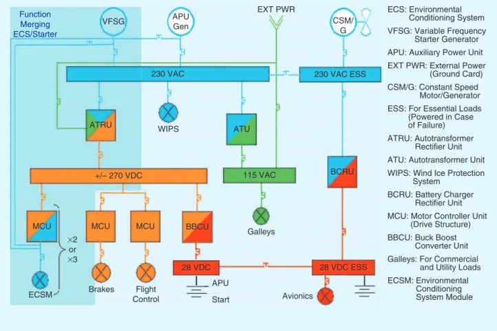
architecture in order to save system mass. One solution should consist of merging several functions supplied with a similar power electronic de-vice [8], which is used for different flight phases. A typical case pro-posed on the B787 bleedless aircraft [9] consists of a function merging of the ECS with the engine start-up sup-plied from a common dual-use PWM inverter. This functional merging is all the more interesting since ratings of both functions are almost compat-ible, which allows considering the electrical engine start-up without any overrating (Figure 4).
One step beyond, in terms of power electronic sharing, was proposed in [24]. The authors have suggested put-ting in parallel base modules consist-ing of three-phase PWM inverters. For example, four 30-kVA inverters can be interleaved (phase-to-phase) with in-ductors to obtain a quadruple switch-ing frequency with a 25% equivalent inductor on each leg, which allows ob-taining a 120-kVA equivalent inverter capable of feeding an air compressor for ECS.
Other innovations in terms of architecture could be proposed with a hybridization of power sources with
storage devices, as for the ground electric vehicles. The advantage of network hybridization is that power sources may be underrated thanks to the storage source capacity to con-tribute to peak power loads. Revers-ible power may also be acceptable for specific operations with hybrid networks. A typical example was pro-posed in [25], [26], for the particu-lar case of the emergency electrical network. In an extreme case of en-gine failure, a ram air turbine (RAT) is classically used to power the es-sential network with flight control actuators, avionic loads, essential lighting, and de-icing. The authors have proposed to hybridize the RAT with super capacitances; an estimat-ed 30% of mass savings was achievestimat-ed through this hybrid architecture together with an original optimized energy management process in which the storage device associated with a dc–dc converter is in charge of the HVDC bus voltage management. Con-sequently, the RAT can be power con-trolled with a maximum power point tracking exactly as in the case of clas-sical wind turbines (Figure 5).
It has been proven that storage devices are capable of handling an im-portant part (40–50%) of peak power consumption mainly due to the opera-tion of flight control actuators.
It should be noted that an HVDC network facilitates coupling between the main source and the storage de-vice. In the event of total engine failure, the transition between normal and emergency operation has to be safely ensured, even while the RAT becomes powered. This transient operation was previously ensured by the hydraulic network on clas-sical aircraft but will have to be managed by the elec-trical storage device in the more-electrical aircraft with an electrical RAT. For this purpose, other storage tech-nologies such as lithium ion batteries could be used to supply the energy needs [27].
The replacement of the RAT with fuel cells has been
FIGURE 3 – Toward an HVDC network architecture.
Release HVAC Standard HVDC 1 Load 1 GCU Vbus G Load 2 Load 3
Other innovations in terms of architecture could be
proposed with a hybridization of power sources with
storage devices, as for the ground electric vehicles.
studied in the CELINA EU project in the context of an emergency network [28]. Replacing the RAT with a fuel cell is technically feasible; a proto-type was embedded on the A320 in 2007. Replacing the APU by a fuel cell is another prospect that would also
allow progression toward a greener aircraft during taxiing.
Toward an Integrated Optimal Design
Due to the increased complexity of electrical devices and network
architecture, simulation at a system level has recently been a key issue for system analysis in order to help engineers in the preliminary design steps as well as in the validation and verification process. During the MOET project [13], a work package
FIGURE 4 – An example of bleedless architecture with the ECS/engine start-up functional merging process.
APU: Auxiliary Power Unit
ATU: Autotransformer Unit ECS: Environmental Conditioning System VFSG: Variable Frequency Starter Generator
EXT PWR: External Power (Ground Card) CSM/G: Constant Speed Motor/Generator ESS: For Essential Loads (Powered in Case of Failure) ATRU: Autotransformer Rectifier Unit
WIPS: Wind Ice Protection System
BCRU: Battery Charger Rectifier Unit MCU: Motor Controller Unit (Drive Structure) BBCU: Buck Boost Converter Unit Galleys: For Commercial and Utility Loads ECSM: Environmental Conditioning System Module Function Merging ECS/Starter VFSG APU Gen EXT PWR CSM/ G 230 VAC ESS 230 VAC WIPS ATRU 115 VAC ATU +/– 270 VDC
MCU MCU MCU BBCU
28 VDC Galleys Avionics 28 VDC ESS APU Start Flight Control Brakes ECSM #2 or #3 BCRU
FIGURE 5 – An example of hybridization of the RAT with super capacitances.
PMSM …
Essential Loads Flight Control Actuator Lighting, De-Icing Avionics (28 V) RAT Storage + Bus Cbus Gain in Terms of System Mass ~–30%
Power (kW) Supercapacitor 3.5F 250V - Storage 25kW
- Filter 0.01Hz - Reg Vcsup 20s 60.0k 40.0k Loads 20.0k (W) 0.0 Maximum: 49929.0 Maximum: 31721.0 Maximum: 21553.0 Minimum: –14098.0 –20.0k 20.0 30.0 40.0 50.0 60.0 70.0 80.0 90.0100.0110.0120.0130.0140.0150.0160.0170.0180.0 t(s) SCap RAT(W) : t(s) Pch PRAT Pstoc
managed by Aeroconseil [22] was fully dedicated to the development of simulation platforms. With model accuracy as the key issue, at least two levels of modeling (functional and behavioral) are required for all equipment. Each device model was first refined with respect to experi-ments. Second, the same model was integrated at the system level. A vir-tual prototyping of two rigs (a first for large aircraft and a second for small aircraft) was finally proposed to analyze a broad set of criteria (compliance with quality and stabil-ity standards, steady state/transient behavior, etc).
“If the 2000s have been the years of network simulation, 2010–2020 could be the decade of integrated optimal design.” Indeed, optimiza-tion has been achieved so far by expert choices through a “test–er-ror” iterative process. Such an ap-proach has proved to be efficient, but designers are never sure of reaching the system optimum, es-pecially when numerous coupling effects are involved. The integrated optimal design approach consists of coupling sizing models with an op-timization algorithm that automati-cally tunes parameters to optimize system criteria (mass, losses, etc.)
while satisfying technological and operational constraints (thermal, compliance with quality/stability standards, etc.). The device weight is certainly the main criterion to be minimized in aircraft systems. However, a tradeoff with losses is classically considered in optimiza-tion approaches, as minimizaoptimiza-tion of masses leads to reduction of sizing and subsequently cost of materials, which usually increases system loss-es and related thermal constraints. Thus, minimizing both criteria at the same time indirectly ensures reli-ability and increases the lifetime of the systems. Robustness and reli-ability are not directly focused in the optimization problem. Reliabil-ity is usually separately analyzed by means of mean time between failure (MTBF) analysis—providers certify a certain MTBF for their equipment. However, if reliability is not a direct objective of optimization, several supplementary issues are consid-ered as “constraints” in the optimi-zation problem, which can be seen as indirectly related to the reliabil-ity issue. For example, the thermal constraints on the power converter as on the electromechanical actua-tor must be verified, as they are cru-cial for system sizing and reliability.
Other constraints such as mechani-cal stress are also verified to indi-rectly ensure system robustness.
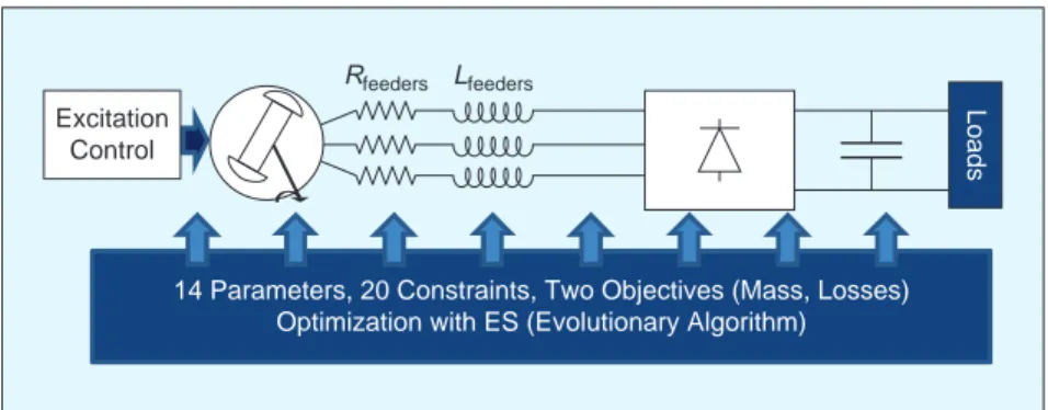
Several optimization studies have recently taken place, for example, in the case of a HVDC power generation system [23]. A complete optimization study of the association between a synchronous generator with con-trolled excitation, a rectifier unit, and an output filter (mainly capaci-tive) was done in combination with evolutionary algorithm to solve this complex problem. In order to solve the quality constraint issue and es-pecially to compare the harmonic spectrum (at the HVDC output of the power channel) with the quality stan-dards required by Airbus, an analyti-cal model of the rectifier is used [29] (Figure 6). Finally, very significant im-provements were obtained as the gen-erator mass was reduced by 30% with respect to a reference solution (ref-erence defined by the supplier for a classic 230 VAC network) for the same level of losses. The mass of the opti-mized whole system including the reducer and its output filter was approximately equivalent to the mass of the reference generator alone!
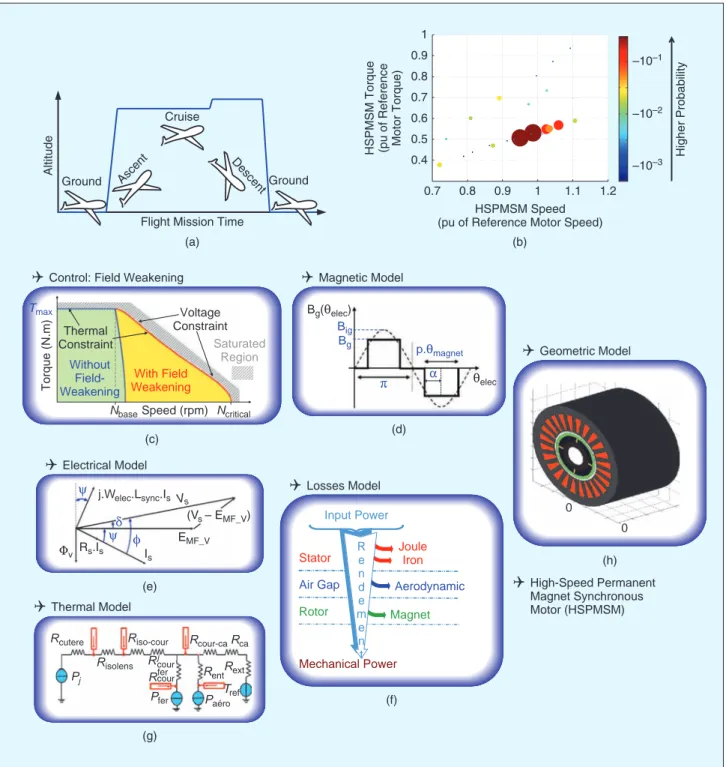
Another analog study was devel-oped in cooperation with Liebherr Aerospace, Inc. in order to minimize mass and losses of an ECS drive in-cluding a high power permanent magnet synchronous machine sup-plied by a PWM VSI connected to an input filter. The approach aimed to take account of the flight mission [see Figure 7(a)] and further explore the integrated optimal design of the whole ECS system, as illustrated in Figure 8.
Figure 7(a) and (b) emphasizes the prime importance of mission profile in the integrated optimal design process. Here, the statistic occurrence in the torque–speed plane of the main oper-ating points is considered to calculate a weighted average of losses along the flight mission. System constraints (electrical, magnetic, mechanical, and thermal) are also evaluated for these variable operations.
Figure 7(c) illustrates the vari-ous fields that aim to model the
FIGURE 6 – Optimization of an HVDC power channel.
Lfeeders Rfeeders
Loads
14 Parameters, 20 Constraints, Two Objectives (Mass, Losses) Optimization with ES (Evolutionary Algorithm) Excitation
Control
“If the 2000s have been the years of network
simulation, 2010–2020 could be the decade of
integrated optimal design.”
high-speed permanent magnet synchronous motor (HSPMSM) in this integrated optimal design, from geometrical or electrical issues to control aspects, considering all losses and thermal constraints.
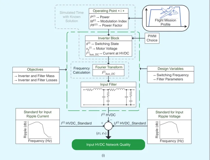
The same kind of approach is con-sidered for the “power supply” part, involving the HVDC network as an input, the input filtering device, and the PWM VSI feeding the HSPMSM.
Losses in the inverter (switching and conducting losses), as in the in-put filter device, are modeled and considered for each operating point of the mission profile. The mass of
main devices (filtering devices, in-verter with cooling plate) is also es-timated. The input/output harmonic constraints are analyzed by means of a “time–frequency approach” as
FIGURE 7 – Multifield modeling of the inverter-fed HSPMSM actuation system for the ECS. Tmax Thermal Constraint Voltage Constraint Saturated Region Without Field-Weakening With Field Weakening
NbaseSpeed (rpm) Ncritical
Torque (N.m)
Control: Field Weakening
Electrical Model Thermal Model (f) Losses Model High-Speed Permanent Magnet Synchronous Motor (HSPMSM) Joule Iron Stator Input Power
Air Gap Aerodynamic
R e n d e m e n t Rotor Magnet Mechanical Power Bg(ielec) ielec r a Big Bg Magnetic Model Geometric Model p.imagnet 0 0 j.Welec.Lsync.Is Rs.Is Vs } } Uv zI s EMF_V (Vs – EMF_V) d Risolens Riso-cour Rj cour Rcour-caRca Rcutere Rfercour Paéro Pfer Tref Rext Rent Pj (b) HSPMSM Speed (pu of Reference Motor Speed) 1 0.9 0.8 0.7 0.6 0.5 0.4 0.7 0.8 0.9 1 1.1 1.2 –10–1 –10–2 –10–3 Higher Probability
HSPMSM Torque (pu of Reference Motor Torque)
(a) (c) (e) (g) (d) (h) Ground
Flight Mission Time Ground
Altitude
Descent
Ascent
Cruise
Another analog study was developed in cooperation
with Liebherr Aerospace, Inc.
illustrated in Figure 7(d): first, a tem-poral simulation with PWM switch-ing in one electrical period of time is achieved for each operation point (flight mission) and for each actuator
solution. Then, a frequency analysis of input/output currents and voltag-es allows the analysis of the quality of waveforms. These are compared with the new HVDC quality standards
provided by Airbus in order to ana-lyze the constraints fulfillment. See [34] for more information.
Two approaches have been com-pared for the component sizing of
FIGURE 7 – Multifield modeling of the inverter-fed HSPMSM actuation system for the ECS (Continued).
(i) Simulated Time with Known Solution Operating Point « i » P(i ) " Power M(i ) " Modulation Index PF(i )" Power Factor PWM Choice U(i ) HVDC_Standard I(i ) HVDC_Standard Frequency Calculation Fourier Transform Input Filter Inverter Block s(i ) " Switching State vs(i )" Motor Voltage i(i ) bus_DC" Current at HVDC
Standard for Input Ripple Voltage
Input HVDC Network Quality
(fI, fv)
Standard for Input Ripple Current Frequency (Hz) Ripple (db) Frequency (Hz) Ripple (db) + -Flight Mission Profile Objectives
" Inverter and Filter Mass " Inverter and Filter Losses
Design Variables " Switching Frequency " Filter Parameters I(i ) HVDC I(i ) bus_DC
FIGURE 8 – Architecture of the ECS.
S1 IconvDC VconvDC IHVDC UHVDC RC2 C2 C1 L1 Cell 1 S3 S5 S2 S4 S6 Axis d Axis q Vq Iq Vd Id Altitude Flight Mission Time Flight Mission Profile Voltage Source Inverter
Control Strategy Standards Voltage Ripple HSPMSM Input Filter HVDC Network
Tcase, TjDiode, TjIGBT Power Quality Ripple DV convDC Partial Transfer Function D V DI Frequency Current Ripple Frequency RC4 C4 C3 L2 Cell 2 Cold Plate Torque Speed THD (%) Motor Current ~
the electromechanical conversion chain:
1) a local and sequential sizing of each system part: a HSPMSM opti-mization loop is associated with a second loop involving the VSI and the input filter
2) a complete integrated design ap-proach investigating the simul-taneous sizing of all coupled components.
Sequential Optimal Sizing
Optimal Sizing of the HSPMSM
The optimal sizing of the HSPMSM is addressed first and can be formulated into an optimization problem using:
■ 11 design variables related to the HSPMSM geometric features
(number of pole pairs, number of slot per pole per phase, radius/ length ratio, equivalent gap, mag-net filling coefficient) electromag-netic variables (yoke induction, current density), and mechanical characteristics (base speed and base torque)
■ 12 constraints associated with geometrical variables (minimum and maximum sleeve thickness, minimum and maximum of copper windings per slots), technological limits (maximum rotational speed, magnet demagnetization), and temperature limits in the different motor parts (magnet, insulator, and yoke)
■ two objectives to be minimized: the HSPMSM mass and the total
average losses estimated over the flight mission—these losses in-clude iron losses (i.e., hysteresis, eddy current, and excess losses) [32], joule losses, aerodynamic losses, and magnet losses.
Some of the constraints are es-timated a priori. Certain other con-straints and losses are evaluated during the flight mission, the latter being modeled by representative points in the torque–speed plane. Total losses are estimated by weight-ing all the losses on each mission point according to their occurrence during the flight. The Pareto optimal plan, represented in Figure 9(a), em-phasizes three particular solutions. With respect to the reference solution previously developed by the supplier,
FIGURE 9 – Pareto optimal solutions for the ECS system: (a) Pareto optimal HSPMSM solutions, (b) Pareto optimal input filter and VSI solutions, and (c) Pareto optimal ECS solutions.
T
otal Embedded Mass:
Input Filter
,
VSI
and HSPMSM (pu of Ref
erence) 0.7 0.8 0.9 1.0 1.1 1.2 1.3 1.4 1.6 1.4 1.2 1.0 0.8 0.6 0.4
Load: Reference Motor Load: Motor 1 Load: Motor 2 Load: Motor 3 Global Solutions (c) 0.6 0.8 1.0 1.2 1.4 1.6 1.8
Input Filter and
VSI Mass
(pu of Ref
erence Input Filter and
VSI) 4.5 4.0 3.5 3.0 2.5 2.0 1.5 1.0 0.5
Load: Reference Motor Load: Motor 1 Load: Motor 2 Load: Motor 3
(a) (b)
Total Average Loss of the Flight Mission (pu of Reference Input Filter, VSI, and HSPMSM)
Total Average Loss of the Flight Mission (pu of Reference Input Filter and VSI) 0.4 0.5 0.6 0.7 0.8 0.9 1.0 1.1 1.2 1.3 0.2
Average HSPMSM Losses (pu)
HSPMSM mass (pu) 0.6 0.7 0.8 0.9 1.0 1.1 1.2 1.3 M1 M3 M2 Reference Motor
these three solutions are obtained at iso level of mass (for Motor 1), at iso level of losses (for Motor 3), the Motor 2 being a tradeoff solution.
Optimal Sizing of the Input Filter—VSI Set
The optimal sizing of the input filter— VSI set—can be formulated into a sec-ond optimization problem using:
■ ten design variables related to the VSI (switching frequency, insulated-gate bipolar transistor current rating) and input filter (in-ductor and capacitor on the HVDC side, capacitor and resistor of the damping branch on the HVDC side, and the same variables on the inverter side)
■ 11 constraints associated with the input filter features (limitation of the damping coefficient in each branch of the filter, maximum root mean square current in the capac-itors), with VSI semiconductors (temperature limits in each region, i.e., diode and insulated-gate bipo-lar transistor junctions, package case), and with quality standards on the electrical network (quality of low- and high-frequency cur-rents on the HVDC network side, maximum ripple of the inverter input voltage, and maximum har-monic distortion of the motor current)
■ two objectives to be minimized: the mass of the input filter and VSI set and the total losses in this subsys-tem during the flight mission – these losses include losses in the input filter (i.e., inductor, resistor, and capacitor losses) and VSI losses (i.e., switching and conduction losses).
Considering the three particu-lar solutions delivered by the first optimization loop for HSPMSM, we
plot the corresponding Pareto plan in Figure 9(b) with a reference VSI input filter solution corresponding with the reference motor. The particular steep shape of the resulting Pareto optimal front is mainly due to the inverter thermal constraint, which strongly limits the switching frequency range keeping power supply losses nearly constant. Consequently, we only consider the VSI input filter configu-ration with minimum mass for each optimal HSPMSM.
ECS Integrated Optimal Sizing
Finally, simultaneous optimization coupling of all ECS components is investigated in a unique optimiza-tion loop. Pareto optimal ECS solu-tions obtained from this approach are illustrated in Figure 9(c) and compared with the three ECS solu-tions resulting from the sequential optimization approach [combination by mass and average losses additions of HSPMSM and VSI input filter solu-tions shown in Figure 9(a) and (b)]. As expected, the simultaneous opti-mization of all the components out-performs the sequential optimization approach. Furthermore, it is interest-ing to note the tradeoff effect between both optimization loops. Indeed, the less massive machines do not nec-essarily exhibit the minimal system mass due to all couplings in these complex devices. As a result, a signifi-cant mass reduction can be obtained through the sequential, particularly the integrated, optimal design of this system for which a whole mass reduc-tion ratio of -26% can be obtained at iso level of losses.
Both previous examples have put forward the interest of the integrated optimal design by coupling optimiza-tion procedure with sizing models for devices. Significant reduction in
terms of mass may be obtained by paying a certain price in terms of complexity of the design process (computation time, cost of model de-velopment, etc.).
Conclusion
Recently, more electrical power needs and systems have been embed-ded in aircraft. The gains in terms of mass are increasing. However, the advantages of the more-electrical aircraft should mainly reside in en-ergy rationalization and management capacity that would allow increasing the availability of the systems. Main-tenance costs could also be reduced from the health monitoring capacity. Electrical systems may also contrib-ute to making aircraft greener for particular operations such as the ground phase.
Nevertheless, the electrical sys-tems and components have to be more mature with increased reli-ability. Their power density should also be increased to save mass. This objective involves numerous areas of progress in terms of power integration at both the component and device level. In particular, the cooling devices must be optimized together with new types of architec-ture in order to avoid “recreating a new secondary hydraulic network.” Research efforts are particularly active in these areas in U.S. and EU industry and also at the university level. Furthermore, as illustrated in the last section, the whole system has to be more optimized; this may be addressed by means of novel inte-grated optimal approaches.
Electric and hybrid electric vehicles would give added impetus to the whole adventure of the more-electrical aircraft since standards, devices, and certain constraints are quite similar.
Biographies
Xavier Roboam ([email protected]) received his Ph.D. de-gree from the Université de Toulouse, Toulouse, France, in 1991. He is with the Université de Toulouse, Toulouse. He has been a full-time researcher
Significant reduction in terms of mass may be
obtained by paying a certain price in terms of
complexity of the design process (computation
time, cost of model development, etc.).
(directeur de recherches CNRS) at the Laboratory of Plasma and Conversion of Electrical Energy of Toulouse since 1992, where he develops integrated design methodologies specifically ori-ented toward multifields devices for embedded (more-electrical aircraft, railway systems, etc.) or renewable energy systems. He is also the head of the team GENESYS (Research Group in Energy Electricity and SYStemics). He is an expert consultant for Airbus in the framework of new architectures and integrated design of electrical networks on board. He is a Member of the IEEE.
Bruno Sareni received his Ph.D. degree from the Ecole Centrale de Lyon, France, in 1999. He is with the Université de Toulouse, France. Cur-rently, he is an assistant professor of electrical engineering and con-trol systems at the Institut National Polytechnique, Toulouse. He is also a researcher at the Laboratory on Plasma and Conversion of Energy (LA-PLACE). His research activities are related to the analysis of complex het-erogeneous power devices in electri-cal engineering and the optimization of these systems using artificial evolu-tion algorithms.
André de Andrade received his M.Sc. degree in electrical engineering from the Institut National Polytech-nique of Toulouse (INPT), France, in 2007. Currently, he is a Ph.D. student working on integrated design by op-timization of an electrically powered air conditioning system (ECS) with high-speed synchronous actuator. His thesis research is conducted in the Laboratory on Plasma and Conversion of Energy (LAPLACE), Toulouse, in the framework of the PREMEP French project in cooperation with Liebherr Aerospace. He is with the Université de Toulouse, France.
References
[1] Advisory Council for Aeronautics Research in Europe. (2010, June). Aeronautics and Air
Transport: Beyond Vision 2020 Towards 2050
[Online]. Available: http://www.acare4europe. org/docs/Towards2050.pdf
[2] J. A Rosero, J. A. Ortega, E. Aldabas, and L. Romeral, “Moving towards a more electric air-craft,” IEEE Aerospace Electron. Mag., vol. 22, no. 3, pp. 3–9, Mar. 2007.
[3] L. Faleiro, “Beyond the more electric air-craft,” Aerospace America, AIAA vol. 43, no. 9, pp. 35–40, Sept. 2005.
[4] (2006) Power Optimized Aircraft project [Online]. Available: www.poa-project.com [5] “L’avion plus électrique,” Revue 3E.I, no. 63,
Mar. 2011.
[6] L. Rubino, B. Guida, F. Liccardo, P. Marino, and A. Cavallo, “Buck-boost DC/DC converter for aeronautical applications,” in Proc. IEEE ISIE
Conf., Bari, Italy, July 2010, pp. 2690–2695.
[7] P. Wheeler, “The more electric aircraft: Why aerospace needs power electronics?” in Proc. EPE Conf., Barcelona, Spain, 2009, pp. 6048–6077.
[8] R. De Maglie, G. Osvald, J. Engstler, A. Engler, and J.-P. Carayon, “Optimized 70 kW power inverter dedicated to future aircraft applica-tion,” in Proc. EPE Conf., Barcelona, Spain, 2009, pp. 1–10.
[9] M. Sinnett. (2007). 787 no-bleed systems: Saving fuel and enhancing operational efficien-cies. Boeing Aero Mag. [Online]. (28). Avail-able: http://www.boeing.com/commercial/ aeromagazine
[10] C. De Oliveira Bizarria and T. Yoneyama, “Prognostics and health monitoring for an electro-hydraulic flight control actuator,” in
Proc. IEEE Aerospace Conf., Big Sky, MT, Mar.
2009. pp. 1–9.
[11] F. Richardeau, J. Mavier, H. Piquet, and G. Gateau, “Fault-tolerant inverter for on-board aircraft EHA,” in Proc. EPE Conf., Aalborg, Denmark, Sept. 2007. pp. 1–9.
[12] L. Faleiro. (2008, Feb.). J Huysseune, Clean sky EU project take off [Online]. Available: , http:// www.cleansky.eu
[13] MOET EU Project. (2006). [Online]. Available: http://www.eurtd.com/moet/
[14] L. M. Tolbert, B. Ozpineci, S. K. Islam, and M. Chinthavali, “Wide bandgap semiconductors for utility applications,” in Proc. IASTED Int.
Conf. Power and Energy Systems (PES), Palm
Springs, CA, 2003, pp. 317–321.
[15] M. Vassilev, Y. Avenas, C. Schaeffer, and J. L. Schanen, “Experimental study of a pulsating heat pipe with combined circular and square section channels,” in Proc. IEEE IAS 42nd Annu.
Ind. Appl. Society Meeting Conf., New Orleans,
2007, pp. 1419–1425.
[16] F. Forest, B. Gelis, J. J. Huselstein, B. Cougo, E. Labouré, and T. A. Meynard, “Design of a 28 V-to-300 V/12 kW multicell interleaved flyback converter using intercell transform-ers,” IEEE-Trans. Power Electron., vol. 25, no. 8, pp. 1966–1974, Aug. 2010.
[17] M. Todeschi, “EMAs for flight controls actuation systems: Perspectives,” in Proc.
Conf. Recent Advances Aerospace Actua-tion Systems Components, Toulouse, France,
pp. 1–8.
[18] X. Feng, J. Liu, and F. C. Lee, “Impedance specifications for stable DC distributed power systems,” IEEE Trans. Power Electron., vol. 17, no. 2, Mar. 2002, pp. 157–162.
[19] X. Liu, A. Forsyth, H. Piquet, S. Girinon, X. Roboam, N. Roux, A. Griffo, J. Wang, S. Bozhko, P. Wheeler, M. Margail, J. Mavier, and L. Prisse, “Power quality and stability issues in more-electric aircraft more-electrical power systems,” in Proc. MOET Forum, Barcelona, Spain, Sept. 2009. pp. 1–9.
[20] M. Charrada, S. Girinon, H. Piquet, and N. Roux, “Equipments characterization methods for stability analyis of dc networds,” in Proc.
2011 IEEE Int. Symp. Industrial Electronics (ISIE), Gdansk, pp. 263–268.
[21] O. Darnis, S. Poignant, K. Benmachou, M. Couderc, Z. Obeid, N. Man Quan, J. Regnier, D. Malec, D. Mary and P. Maussion, “PREMEP, a research project on electric motor optimiza-tion diagnostic and power electronic for aero-nautic applications,” in Proc. Int Conf. Recent
Advances on Aerospace Actuation Systems and Components, Toulouse, France, May 2010,
pp. 127–132.
[22] J. Faucher, Aeroconseil Aircraft Eng, “Simula-tion study of new aircraft electrical power network performances,” in Proc. MOET Forum, Barcelona, Spain, 2009, [Online]. Available: http://www.eurtd.com/moet/PDF/B.pdf. [23] H. Nguyen-Huu, N. Retière, F. Wurtz,
X. Roboam, B. Sareni and D. Alejo, “Optimal sizing of an embedded electrical system with an approach for restricting the search space,”
COMPEL-Int. J. Comput. Math. Electr. Electron. Eng., vol. 28, no. 5, pp. 1141–1154, 2009.
[24] L. Prisse, D. Ferrer, H. Foch, and A. Lacoste, “New power centre and power electronics sharing in aircraft,” in Proc. EPE, Barcelona, Spain, Sept. 2009.
[25] X. Roboam, O. Langlois, H. Piquet, B. Morin, and C. Turpin, “Hybrid power generation system for aircraft electrical emergency net-work,” IET Trans. Electr. Syst. Transp., vol. 1, no. 4, pp. 148–155, 2011.
[26] K. Rafal, B. Morin, X. Roboam, E. Bru, C. Turpin and H. Piquet, “Experimental validation of hy-brid emergency electrical network for aircraft application,” in Proc. IEEE VPPC Conf., Lille, France, 2010.
[27] R. Rigo Mariani, F. Lacressonniere, G. Fontes and X. Roboam, “Design of power converter devices embedded in a hybrid emergency network for more electrical aircraft,” in Proc.
Electrimacs Conf., Cergy-Pontoise, France,
2011.
[28] M. G. Arreguy, “Theoretical study of a power generation unit based on the hybridiza-tion of a fuel cell stack and ultracapaci-tors,” Ph.D. thesis, Univ Toulouse, Toulouse, France, 2007. [Online]. Available: http:// ethesis.inp-toulouse.fr/archive/00000521/01/ garcia_arregui.pdf
[29] H. Nguyen Huu, L. Gerbaud, N. Retiere, J. Rou-det and F. Wurtz, in Proc. IEEE VPPC Conf., Lille, France, 2010.
[30] X. Roboam, “New trends and main challenges of electrical networks embedded in ‘more electrical aircraft’,” in Proc. IEEE ISIE Conf.
Invited Keynote Paper, Gdansk, June 2011, pp.
26–31.
[31] A. Boglietti, A. Cavagnino, A. Tenconi, and S. Vaschetto, “The safety critical electric ma-chines and drives in the more electric aircraft: A survey,” in Proc. IEEE 35th Annu. Conf. Ind.
Electron., 2009, pp. 3–5.
[32] T. L. Mthombeni and P. Pillay, “Physical basis for the variation of lamination core loss coeffi-cients as a function of frequency and flux den-sity,” in Proc. IEEE 32nd Annu. Conf. Industrial
Electronics, IECON, 2006, pp. 1381–1387.
[33] R. Lai, F. Wang, P. Ning, D. Zhang, D. Jiang, R. Burgos, D. Boroyevich, and K. J. Karimi, “A high-power-density converter,” IEEE Ind.
Elec-tron. Mag., vol. 4, no. 4, pp. 4–12, Dec. 2010.
[34] A. de Andrade, B. Sareni, X. Roboam, and M. Couderc, “Multilevel optimization of electrical environmental conditioning systems for more electrical aircraft,” in Proc. OIPE Conf., Gent, Belgium, 2012, pp. 124–125.
[35] F. Koliatene, T. Lebey, J. P. Cambronne, and S. Dinculescu, “Impact of the aeronautic envi-ronment on the partial discharges ignition: A basic study,” in Proc. IEEE Int. Symp. Electrical
Insulation (ISEI), Vancouver, BC, Canada, 2008,