HAL Id: hal-02392625
https://hal.archives-ouvertes.fr/hal-02392625
Submitted on 4 Dec 2019
HAL is a multi-disciplinary open access
archive for the deposit and dissemination of
sci-entific research documents, whether they are
pub-lished or not. The documents may come from
teaching and research institutions in France or
abroad, or from public or private research centers.
L’archive ouverte pluridisciplinaire HAL, est
destinée au dépôt et à la diffusion de documents
scientifiques de niveau recherche, publiés ou non,
émanant des établissements d’enseignement et de
recherche français ou étrangers, des laboratoires
publics ou privés.
A Low Power Cryogenic Sapphire Oscillator with better
than 10-15 short term frequency stability
Christophe Fluhr, Benoît Dubois, Valérie Soumann, Guillaume Le Tetu,
Vincent Giordano, Serge Grop, Julien Paris
To cite this version:
Christophe Fluhr, Benoît Dubois, Valérie Soumann, Guillaume Le Tetu, Vincent Giordano, et al..
A Low Power Cryogenic Sapphire Oscillator with better than 10-15 short term frequency stability.
International Frequency Control Symposium and European Frequency and Time Forum, Apr 2019,
Orlando, United States. �hal-02392625�
A Low Power Cryogenic Sapphire Oscillator
with better than
10
−15
short term frequency stability
C. Fluhr
∗, B. Dubois
∗, V. Soumann
†, G. Le Tetˆu
†, V. Giordano
†and S. Grop
‡J. Paris
§—–
∗FEMTO Engineering
15B avenue des Montboucons, 25030 Besanc¸on Cedex, FRANCE —–
†FEMTO-ST Institute, Time & Frequency Dpt.
26 Chemin de l’Epitaphe, 25030 Besanc¸on Cedex, FRANCE —–
‡Spectratime
Vauseyon 29, 2000 Neuchˆatel, SWITZERLAND —–
§ My Cryo Firm SARL
104 Avenue de la R´esistance, 93100 Montreuil, FRANCE
Abstract—In the field of Time and Frequency metrology, the most stable frequency source is based on a microwave whispering gallery mode sapphire resonator cooled near 6 K. Provided the resonator environment is sufficiently free of vibration and tem-perature fluctuation, the Cryogenic Sapphire Oscillator (CSO) presents a short term fractional frequency stability of better than 1 × 10⁻¹⁵. The recent demonstration of a low maintenance CSO based on a pulse-tube cryocooler paves the way for its deployment in real field applications. The main drawback which limits the deployment of the CSO technology is the large electrical consumption (three-phase 8 kW peak / 6 kW stable operation) of the current system.
In this paper, we describe an optimized cryostat designed to operate with a low consumption cryocooler requiring only 3 kW single phase of input power to cool down to 4 K a sapphire resonator. We demonstrate that the proposed design is compatible with reaching a state-of-the-art frequency stability.
I. INTRODUCTION
The Cryogenic Sapphire Oscillator (CSO) is the microwave oscillator which features the highest short-term frequency sta-bility [1]. With the advent of low maintenance CSO based on a closed cycle cryocooler, 1 × 10⁻¹⁵fractional frequency stabil-ity is now avaible for real field applications. The autonomous CSO enables the operation of laser-cooled microwave clocks at the quantum limit [2], [3], the improvement of the resolution in Very Long Baseline Interferometry (VLBI) and in the deep-space netwoks for space-vehicle ranging and Doppler tracking [4]–[9]. It can enhance the calibration capability of Metrological Institutes, and help for the qualification of high performances clocks and oscillators [10], [11]. Nevertheless, the large electrical consumption (three-phase 8 kW peak/6 kW stable operation) of the current system is the main obstacle to the deployment of the CSO technology.
This paper describes an optimized cryostat designed to operate with a low consumption cryocooler requiring only 3 kW single phase of input power to cool down to 4 K a sapphire resonator. The proposed design is compatible with reaching a state-of-the-art frequency stability.
II. HIGH PERFORMANCESCSOS OF THE
OSCILLATOR-IMPPROJECT
The Oscillator IMP project targets at being a facility ded-icated to the measurement of noise and short-term stability of oscillators and devices in the whole radio spectrum (from MHz to THz), including microwave photonics. A set of three CSOs constitutes one of the reference of the Oscillator IMP metrological platform [1]. The figure 1 shows these three instruments that have been successively assembled since 2012.
They are in principle equivalent, but differ from several de-tails. Two of them (CSO-1 and CSO-2) are equiped with a PT-405 cryocooler from Cryomech requiring a 6 kW compressor. The last one incorpores a PT-410 and a 8 kW compressor. The three-cornered-hat method has been used to extract the individual fractional frequency stability of each CSO. The three oscillators present a stability better than 1 × 10⁻¹⁵ between 1 s and 10,000 s (see Fig. 2) [12].
−16 10 10−15 CSO−2 CSO−3 CSO−1 1 10000 100000 Integration Time (s) Individual ADEV 100 10 1000
Fig. 2. The three individual ADEV obtained from the 3-cornered-hat method.
III. THEULISSPROJECT
One of these CSOs, codenamed ULISS, can be transported with a small truck. In two years ULISS visited several Eu-ropean sites, traveling more than 10,000 km [11]. Measuring ULISS before and after traveling, we can validate stability and spectral purity at destination. It has been used for example to check on the stability of a laser stabilized on a ULE cavity, and to run with a cold atom fountain at SYRTE (see Fig. 3).
Fig. 3. ULISS in SYRTE, where it was used as flywheel oscillator to run the fountain atomic clock.
The ULISS Odissey was the opportunity to demonstrate the potentiality and the reliability of our technology. It was also pointed out that the electrical consumption and the heat released by the compressor could turn out to hinder the deployment of this technology. The project ULISS-2G was
launched to solve this technological difficulty with the aim to divide by two the electrical consumption.
IV. NEWCRYOSTATDESIGNOVERVIEW
Our design is based on a 3 kW PT-403 cryocooler from Cry-omech delivering typically 0.25 W at 4 K. For this cryocooler the frequency of the thermodynamical cycle is about 1.4 Hz. The levels of mechanical displacement of the 2nd stage cold plate induced by the gas flow inside the Pulse-Tube are 25 µm peak-to-peak in the vertical direction and 12 µm peak-to-peak in the horizontal one [13]. The temperature variation on the PT 2nd stage is typically 100 mK rms.
Our main objective is to develop a cryostat as simple as possible avoiding a high cost and a complex optimisation. Thus we choose a simple passive filtering inspired from Tomaru et al. [14]. Fig. 4 shows an overview of the CSO cryostat. sensors Temperature Cold head flexible tube Bellows Springs Rotary Valve Thermal shields Microwave cable Flexible link thermal Vacuum can 300 K 1st Stage Resonator Thermal ballast 2nd Stage Heater
Fig. 4. CSO cryostat: design overview (left), picture of the prototype (right). The rotary valve is located remotely from the cryostat.
The microwave resonator is rigidly attached to the top flange of the cryostat whose external surrounding walls are made as rigid as possible keeping reasonable mass and space. The rotary valve unit, which could generate large vibrations, is separated from the cold-head. The cold-head itself still remains an important source of vibrations. Thus it is supported by a set of 8 springs providing the vibration insulation. A bellows makes the connection with the vacuum can. The remaining vibrations come from the pressure oscillation in the pulse tube and regenerator transmitted to the cold-stage through thermal links. The vibration reduction is obtained by using flexible metal heat links (copper braids). The temperature variations are passively filtered by the thermal ballast constituted by the stainless steel top flange of the 2nd stage thermal shield.
Associated with the thermal resistance of the flexible thermal link it is equivalent to a first order filter. The cavity is attached to the thermal ballast. A thermal sensor and a 25 Ω resistive heater are anchored in the cavity foot. They allow the control of the resonator temperature. Four microwave UT-085 semirigid Be/Cu cables link the resonator assembly to the external circuits. These cables are thermalized on each stage.
To optimize this design with regard to the CSO performance, trade-offs have been made between the vibration attenuation, the thermal conductance of the links and the ballast thermal mass [15].
The figure 5 shows a 3D-view of the cryostats internal part and a picture of the 2ndstage suspension. The V-shaped
suspension rods enable to stiffen the suspension in the transverse direction. To limit the thermal conduction these suspensions are made in Mylar and simply realized using a 3D-printer.
Fig. 5. Internal 3D view of the cryostat and picture of the 2nd stage suspension.
V. EXPERIMENTAL VALIDATION
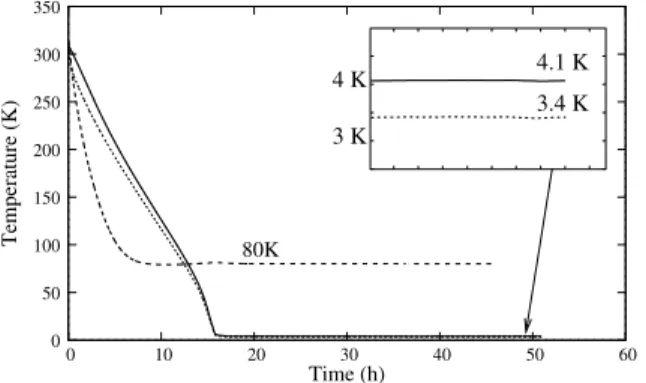
A resonator was assembled and mounted inside the cryostat. The sapphire resonator is made from a Kyropoulos monocrys-tal [16]. The temperatures evolution during the cool down is shown in Fig. 6: 3.4 K 80K 4.1 K 3 K 0 50 100 150 200 250 300 350 0 10 20 30 40 50 60 Temperature (K) Time (h) 4 K
Fig. 6. Temperatures evolution during cool-down. Resonator temperature (bold line), 2nd-stage shield temperature (dotted line), 1st stage shield tem-perature (dashed line).
Fig. 7 shows the modulus of the resonator response around the whispering gallery mode at ν0∼ 10 GHz measured at the
minimum achievable resonator temperature, i.e. 4.1 K. The bandwidth is 7.2 Hz equivalent to a loaded Q-factor QL ∼
1.4 × 10⁹.
The resonator temperature is stabilized using a commercial temperature controller. By changing the temperature set-point step-by-step we obtain the resonator frequency evolution (see Fig. 8). The resonator presents a turnover temperature equals to 5.24 K. Stabilized at this point, its frequency is no longer
ν−ν0(Hz) 7.2 Hz −40 −20 −40 −20 0 20 40 |S21| (dB) −30
Fig. 7. Transmissiom resonator response around the resonance frequency ν0≈ 10 GHz. 0 4 4.5 5 5.5 6 6.5 Temperature (K) Frequency shift (Hz) 5.24 K −100 −80 −60 −40 −20
Fig. 8. Resonator frequency evolution around the turnover temperature.
sensitive to the temperature fluctuations and a high frequency stability can be obtained.
This resonator has been inserted in an oscillator loop complemented with a Pound servo and a power stabilization. The oscillator delivers 10 dBm at ν0= 10.02 GHz.
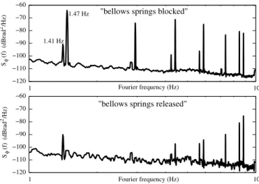
In a first step, the close-to-carrier phase noise of the prototype has been evaluated. Its 10 GHz output signal is mixed with those delivered by one of the ultra-stable 6 kW CSO. The obtained 26 MHz beatnote is sent to a Symmetricom 5125A phase noise test set. The observed phase noise is shown in the Fig. 9. The upper curve was recorded when the springs supporting the PT cold-head were intentionally blocked: the bolt getting through every spring was tightened. In this case the vibration of the cold-head are almost integrally transferred to the cryostat. The spectrum shows a large line at 1.47 Hz and its harmonics, which are the signature of the cold-head vibration. The other smaller line at 1.41 Hz comes from the 6 kW CSO. When the springs are released (see Fig. 9 lower curve), the 1.47 Hz line almost completely disappears and its harmonics are also strongly attenuated. From this second spectrum, the resonator displacement is estimated to be less than 0.1 µm.
To evaluate the frequency performance of the prototype, it has been simultaneously compared to two high stability 6 kW CSOs. The three-cornered-hat method [12], [17] has been used to extract the prototype fractional frequency stability.
φ Fourier frequency (Hz) Fourier frequency (Hz) 2 φ S (f) (dBrad /Hz) 2 S (f) (dBrad /Hz) −70 −60 −120 −110 −100 −90 −80 −70 −60 −120 1 10 1.47 Hz 1.41 Hz
"bellows springs blocked"
"bellows springs released"
−110 1 −100 −90 −80 10
Fig. 9. Upper curve: Phase noise when the bellows springs are blocked. Lower curve: bellows springs realesed.
The result is presented in the Fig. 10. The new instrument
ULISS−2G 10−16 10 10−17 −14 10−15 10000 100 1000 10
Fractional Frequency Stability
Integration Time (s) 1
Fig. 10. Fractional frequency stability of the 3 kW prototype evaluated using the three-cornered-hat-method with two ultra-stable 6 kW CSOs used as references [12].
presents a fractional short term frequency stability below 1 × 10⁻¹⁵. At long integration time the fractional frequency stability is degraded proportionnaly to τ . The observed drift (approximately 3 × 10⁻¹⁴/day) could result from the large temperature variations inside the laboratory. The three ref-erence CSOs have recently been moved in a temperature stabilized room at 22◦C ±0.5◦C. The new prototype stays in another experimental room equipped only with the standard air-conditioning system of the flat. Depending on the sunlight the temperature near the cryostat can vary of several degrees during the day.
VI. CONCLUSION
A new cryostat has been designed to cool-down a sapphire microwave resonator intented to serve as the frequency refer-ence of an ultra-stable oscillator. This new cryostat is equipped with a 3 kW PT cryocooler sufficient to reach a temperature of 4.1 K. A specially designed suspension permits to filter
the 1.4 Hz vibration generated by the pulse-tube. A prelim-inary performance evaluation shows a short term fractional frequency stability below 1 × 10⁻¹⁵ for 1 s≤ τ ≤ 2000 s.
ACKNOWLEDGMENT
This work has been realized in the frame of the ANR projects: Equipex Oscillator-Imp and Emergence ULISS-2G. The authors would like to thank the Council of the R´egion de Franche-Comt´e for its support to the Projets d’Investissements d’Avenir and the FEDER (Fonds Europ´een de D´eveloppement Economique et R´egional) for funding one CSO.
REFERENCES
[1] V. Giordano, S. Grop, C. Fluhr, B. Dubois, Y. Kersal´e, and E. Rubi-ola, “The autonomous cryocooled sapphire oscillator: A reference for frequency stability and phase noise measurements,” Journal of Physics: Conference Series, vol. 723, no. 1, p. 012030, 2016.
[2] G. Santarelli, P. Laurent, P. Lemonde, A. Clairon, A. G. Mann, S. Chang, A. N. Luiten, and C. Salomon, “Quantum projection noise in an atomic fountain: A high stability cesium frequency standard,” Physical Review Letters, vol. 82, June 1999.
[3] M. Abgrall, J. Gu´ena, M. Lours, G. Santarelli, M. Tobar, S. Bize, S. Grop, B. Dubois, C. Fluhr, and V. Giordano, “High-stability com-parison of atomic fountains using two different cryogenic oscillators,” IEEE transactions on ultrasonics, ferroelectrics, and frequency control, vol. 63, no. 8, pp. 1198–1203, 2016.
[4] G. J. Dick, D. G. Santiago, and R. T. Wang, “Temperature compensated sapphire resonator for ultra–stable oscillator capability at temperatures above 77K,” IEEE Transactions on Ultrasonics, Ferroelectrics and Frequency Control, vol. 42, no. 5, pp. 812–819, 1995.
[5] S. Grop, P. Y. Bourgeois, N. Bazin, Y. Kersal´e, E. Rubiola, C. Langham, M. Oxborrow, D. Clapton, S. Walker, J. De Vicente, and V. Giordano, “ELISA: A cryocooled 10 GHz oscillator with 10−15frequency
stabil-ity,” Review of Scientific Instruments, vol. 81, no. 2, p. 025102, 2010. [6] S. Grop, P.-Y. Bourgeois, E. Rubiola, W. Sch¨afer, J. De Vicente,
Y. Kersal´e, and V. Giordano, “Frequency synthesis chain for the ESA deep space network,” Electronics Letters, vol. 47, pp. 386–388, Mar. 17, 2011.
[7] N. Nand, J. Hartnett, E. Ivanov, and G. Santarelli, “Ultra-stable very-low phase-noise signal source for very long baseline interferometry using a cryocooled sapphire oscillator,” Microwave Theory and Techniques, IEEE Transactions on, vol. 59, pp. 2978–2986, Nov 2011.
[8] S. Doeleman, T. Mai, A. E. E. Rogers, J. G. Hartnett, M. E. Tobar, and N. Nand, “Adapting a cryogenic sapphire oscillator for very long baseline interferometry,” Publications of the Astronomical Society of the Pacific, vol. 123, no. 903, pp. pp. 582–595, 2011.
[9] M. Rioja, R. Dodson, Y. Asaki, J. Hartnett, and S. Tingay, “The impact of frequency standards on coherence in VLBI at the highest frequencies,” The Astronomical Journal, vol. 144, no. 4, p. 121, 2012.
[10] V. Dolgovskiy, S. Schilt, N. Bucalovic, G. Di Domenico, S. Grop, B. Dubois, V. Giordano, and T. S¨udmeyer, “Ultra-stable microwave generation with a diode-pumped solid-state laser in the 1.5-µm range,” Applied Physics B, vol. 116, no. 3, pp. 593–601, 2014.
[11] V. Giordano, S. Grop, B. Dubois, P.-Y. Bourgeois, Y. Kersal´e, E. Rubiola, G. Haye, V. Dolgovskiy, N. Bucalovicy, G. D. Domenico, S. Schilt, J. Chauvin, and D. Valat, “New generation of cryogenic sapphire microwave oscillator for space, metrology and scientific applications,” Review of Scientific Instruments, vol. 83, 2012.
[12] C. Fluhr, S. Grop, B. Dubois, Y. Kersal´e, E. Rubiola, and V. Giordano, “Characterization of the individual short-term frequency stability of cryogenic sapphire oscillators at the 10−16level,” IEEE Transactions on Ultrasonics, Ferroelectrics and Frequency Control, vol. 63, no. 6, pp. 915–921, 2016.
[13] C. Wang and P. E. Gifford, “Development of 4 K pulse tube cryorefrig-erators at cryomech,” Advances in Cryogenic Engineering: Proceedings of the Cryogenic Engineering Conference-CEC, vol. 613, no. 1, pp. 641– 648, 2002.
[14] T. Tomaru, T. Suzuki, T. Haruyama, T. Shintomi, N. Sato, A. Yamamoto, Y. Ikushima, R. Li, T. Akutsu, T. Uchiyama, and S. Miyoki, Cryocoolers 13, ch. Vibration-Free Pulse Tube Cryocooler System for Gravitational Wave Detectors, Part I: Vibration-Reduction Method and Measurement, pp. 695–702. Boston, MA: Springer US, 2005.
[15] C. Fluhr, B. Dubois, S. Grop, J. Paris, G. Le Tetˆu, and V. Giordano, “A low power cryocooled autonomous ultra-stable oscillator,” Cryogenics, vol. 80, pp. 164–173, 2016.
[16] V. Giordano, C. Fluhr, S. Grop, and B. Dubois, “Tests of sapphire crystals manufactured with different growth processes for ultra-stable microwave oscillators,” IEEE Transactions on Microwave Theory and Techniques, vol. 64, pp. 78–85, Jan. 2016.
[17] J. Gray and D. Allan, “A method for estimating the freqeuncy stability of an individual oscillator,” in Proc 28th Ann. Symp. on Frequency Control., (Fort Monmouth, (NJ) US), pp. 243–246, May 29-31 1974.