HAL Id: hal-00832354
https://hal-univ-rennes1.archives-ouvertes.fr/hal-00832354v2
Submitted on 24 Jun 2013
HAL is a multi-disciplinary open access archive for the deposit and dissemination of sci-entific research documents, whether they are pub-lished or not. The documents may come from teaching and research institutions in France or abroad, or from public or private research centers.
L’archive ouverte pluridisciplinaire HAL, est destinée au dépôt et à la diffusion de documents scientifiques de niveau recherche, publiés ou non, émanant des établissements d’enseignement et de recherche français ou étrangers, des laboratoires publics ou privés.
A single sediment-Microbial Fuel Cell powering a
wireless telecommunication system
Yohann R J Thomas, Matthieu Picot, Arnaud Carer, Olivier Berder, Olivier
Sentieys, Frédéric Barrière
To cite this version:
Yohann R J Thomas, Matthieu Picot, Arnaud Carer, Olivier Berder, Olivier Sentieys, et al.. A single sediment-Microbial Fuel Cell powering a wireless telecommunication system. Journal of Power Sources, Elsevier, 2013, 241, pp.703-708. �10.1016/j.jpowsour.2013.05.016�. �hal-00832354v2�
1
A single sediment-Microbial Fuel Cell powering a wireless telecommunication system
Yohann R. J. Thomas a, Matthieu Picot a, Arnaud Carer b, Olivier Berder b, Olivier Sentieys b and Frédéric Barrière a,*
a
Equipe MaCSE, Institut des Sciences Chimiques de Rennes, Université de Rennes 1, CNRS UMR n° 6226, Rennes 35042 (France).
b
IRISA, INRIA, Université de Rennes 1, Equipe Cairn.
* Corresponding author. Tel.: (+33) 223235943; fax: (+33) 223236797. E-mail address: frederic.barriere@univ-rennes1.fr
Abstract
We report the ability of a single sediment-Microbial Fuel Cell (MFC) to power wireless sensor network (WSN) nodes. Such a system is able to collect information from sensors and to transmit it to sinks. In particular, the PowWow platform presented here is combining an open and modular hardware design with an open-source software with a very light memory footprint and relying on event-driven programming. It includes energy harvesting capabilities and is able to adapt its radio data transmission behavior to the available energy supplied by the sediment-MFC. The MFC developed in this study successfully powered the WSN and results showed very stable performances over a long time frame with a high rate of signals sent from a source to a receptor connected to a computer. This sediment-MFC is moreover simple to produce and handle, with no membrane or artificial catalysts.
Key words: Sediment-Microbial Fuel Cell; Sensor Networks; Wireless Communication;
2
1. Introduction
Microbial fuel cells (MFC) have attracted a lot of interest in the last decade [1], as they produce electricity from a wide range of organic substrates including biomass and wastewater, using living bacteria as the electrode catalyst [2]. Several MFC architectures have appeared in the literature of which the simplest design is the sediment-MFC. In such a configuration, there is a single chamber containing the electrolyte with usually no physical separation between the anode and the cathode [3]. The cathode is commonly exposed to ambient oxygen at the air/water interface while the anode is close to anaerobic conditions as found in the sediment at the bottom of the cell. Indeed there is a decreasing oxygen gradient from the electrolyte surface and cathodic zone (top) to the anodic zone (bottom) [4].
Although MFCs produce only moderate amounts of energy (below ca. 1 mW cm-2 (10 W m-2) of projected electrode area), these devices could be useful power sources for systems that demand only low power. For example chemical and wireless sensors, or miniaturized telecommunication systems, could be powered by MFCs provided that these electronic devices integrate an appropriate energy management program. To the best of our knowledge, only a few studies have shown the viability of MFC-powered electronic systems. Tender et al. [5] have shown the first demonstration of an MFC as a viable power supply for a meteorological buoy in an estuary. Other applications have been proposed such as the powering of robots [6], wireless temperature sensor using sediment MFCs with vertical arrangement of electrodes [7] and other wireless sensors [8,9]. Moreover, MFCs as power sources have the advantage to be easily placed where the energy is needed, like in remote locations [10].
3 For most applications, the voltage output of a single MFC is usually too low (< 1 V) to run electronic systems. It is then advantageous to control the electronic system by a DC/DC inductive converter or use stacks of multiple small-scale MFCs, in series, parallel and series– parallel configurations [6]. Those configurations increase the total power output compared to a single cell [11]. However, a connection in series of the fuel cells leads to operating problems such as voltage reversal in one of the cell when the anode potential shifts to positive values. This happens when a cell with limited performances is operated at high currents [11] or when a single MFC is connected to an external load that is too demanding [12].
Some authors have reported the powering of wireless sensors thanks to a capacitor that stores the energy produced by an MFC and hence permits its intermittent use [13]. A recent study [14] has demonstrated that duty cycling experiments performed with periodic resistance connection and disconnection allows the MFC to be operated at electrical loads below the MFC internal resistance. The authors concluded that shorter cycles lead to an increase in power generation. An alternative solution is to implement a control which allows the cell to work at its maximum power conditions [15-18].
In this study, the aim is to develop a power management system based on a single, cost effective and efficient sediment-Microbial Fuel Cell and to adapt this power source to the Wireless Sensor Network (WSN) context.
A WSN is a collection of autonomous nodes with the abilities to collect information from sensors and to transmit this information to one or several sinks. WSN nodes are usually powered with batteries or self-powered with energy harvesting solutions [19,20]. The PowWow platform (Power Optimized hardware/software frameWOrk for Wireless sensor nodes) [21,22] has been developed at the University of Rennes 1 by the Cairn research team of Irisa/Inria. This platform has the specificity to include energy harvesting capabilities and to adapt the behavior of radio data transmission to the available energy. The PowWow platform
4 has been adapted to the sediment-MFC context and therefore, the sensor node (or mote) is able to operate in degraded (intermittent) mode when the energy supplied by the sediment-MFC is decreasing.
The advantages of our set-up are the use of a simple configuration based on a single sediment-MFC with no added catalysts other than naturally occurring bacteria and no pre-treatment of any of the materials (carbon electrodes), that are utilized as received from the manufacturers. The paper is organized as follows. After a brief description of the building of the MFC, its stable performances are characterized by electrochemical measurements. The PowWow platform power consumption is analyzed before realizing the powering experiment by the MFC. Finally, data transmission analyses show that the system is a suitable adequate energy harvesting solution for this kind of application.
2. Materials and methods
2.1 Microbial Fuel Cell set up
The sediment-MFC (Fig. 1) was constructed using a 10 cm diameter cylindrical tube of polyvinyl chloride for a total volume around 0.8 L. The anode was made of graphite granules forming a bottom layer of about 4 cm thickness (Le Carbone, Belgium) and a graphite rod (5 mm diameter from Morganite Luxembourg SA) as the current collector.
5
Figure 1. Sediment-MFC with graphite granules as anode and carbon felt from MAST Carbon Ltd (image
obtained with a JEOL JSM-6301F Scanning Electron Microscope) as cathode.
The cathode was made of a carbon felt disc (10 cm diameter and 2 mm thickness as received from MAST Carbon Ltd., Guildford, UK). This non-woven activated carbon is highly microporous with a specific surface area of 1650 m2 g-1 determined by N2 adsorption isotherm
with the B.E.T. method [23] on an Autosorb-1 from Quantachrome Instruments. The distance between the floating cathode and the anodic graphite granules bed was ca. 4 cm.
The electrolyte was prepared as described in Picot et al. [24] by mixing garden compost with sodium acetate (20 mM) in 20 mM phosphate buffer solution (pH 7) with 10 mL L-1 of a macronutrient solution (28 g L-1 NH4Cl, 10 g L-1 MgSO4.7H2O and 0.57 g L-1 CaCl2.2H2O); 1
mL L-1 of a trace element solution (2 g L-1 FeCl2.4H2O, 1 g L-1 CoCl2.6H2O, 0.5 g L-1
MnCl2.4H2O, 0.05 g L-1 ZnCl2, 0.05 g L-1 H3BO3, 0.04 g L-1 CuCl2.2H2O, 0.07 g L-1
(NH4)6Mo7O2.5H2O, 1 g L-1 NiCl2.6H2O, 0.16 g L-1 Na2SeO3.5H2O and 2 mL L-1 of HCl
6
2.2 Electrochemical measurements
Reactors were operated in a batch mode at room temperature (20 ± 5°C) and under a 1 kΩ external resistor. Cell voltage and electrode potentials were measured using a digital multimeter (Agilent U1253B). When the biofilm had developed, polarization and power curves were recorded under steady-state conditions using a potentiostat (Autolab PGSTAT302N) and a two-electrodes cell configuration (using the anode and cathode of the microbial fuel cell). A scan rate of 10-3 mA s-1 was applied from zero current to the current found at cell potential equal to 0.05 V (before short circuit). Chronoamperometry curves were obtained with the same equipment fixing the cell potential to 0.3 V (voltage found at near maximum power conditions) and measuring the current every 10 s during several days.
2.3 WSN platform description
PowWow [21,22,25,26] is a platform developed by the project team Cairn at Inria/Irisa (University of Rennes 1), combining an open and modular hardware design with an open-source software having a very light memory footprint and relying on event-driven programming.
The platform can assemble up to four stackable electronics boards. i) Radio board:
The radio board is the CC2420EM from Texas Instrument including the low-power 802.15.4 radio transceiver CC2420. The CC2420 component is used to send and receive radio packets on the 2.4 GHz Industrial, Scientific and Medical (ISM) band at
7 a maximal data rate of 250 kbit s-1. A small form factor 2.4 GHz antenna is connected to the board via a SubMiniature version A (SMA) connector.
ii) Main controller board
The main controller board is based on the 16-bit low-power MSP430 microprocessor from Texas Instrument. In terms of embedded software, a custom wireless protocol stack based on an optimized asynchronous Media Access Control (MAC) protocol, a simple geographic routing protocol and a very compact software code (protocol stack around 6 kbit and typical application between 4 and 5 kbit) have been developed in a parameterized and upgradeable way. Low-power sensors can be connected via an Inter-Integrated Circuit (I2C) bus to the board and controlled by the MPS430. An RS232 bus is also available to communicate with a host computer.
iii) A Field-Programmable Gate Array (FPGA) board
A FPGA board can be inserted between the controller and the radio boards to enhance the computing power and the energy efficiency of the system [22]. To this end, the FPGA is used to accelerate the processing of some specific tasks and consequently save power since the energy efficiency of the FPGA is much higher than that of the microcontroller for data-flow processing. Currently this board integrates a low power FPGA Igloo from Microsemi Soc Product Group, the AGL125 (125000 gate-equivalent, 32 kbit of RAM memory, 1 kbit of flash memory), which consumes respectively 2.2 µW, 16 µW or from 1 to 30 mW in sleep, freeze or active modes according to usage. Note that this board is not used in the present sediment-MFC study.
8 iv) The energy harvesting board
The last board is the RCup board (Fig. 2) which is the energy harvesting system interfacing the PowWow node with the sediment-MFC power source. The RCup board is based on the ultra-low-voltage step-up converter LTC3108 from Linear Technology. Associated with a 1:20 transformer (T), this DC/DC converter is compatible with the MFC low-voltage output (< 1 V).
Figure 2. Schematic of the MFC energy harvesting system with the RCup board. MFC: Microbial Fuel Cell ; T:
1-20 transformer compatible with low-voltage (< 1 V) ; LTC3108 : ultra-low-voltage step-up converter ; Cout : 680 μF capacitor used as an energizer buffer ; Cstore : 0.4 F super-capacitor ; Vout : voltage at Cout (1.7 to 3.3 V) ; En : Enabling of the radio transmission system ; PowWow: radio transmission system.
The rest of this section gives more insights into the energy harvesting system shown in Fig. 2. The ultra-low voltage step-up converter and power manager LTC3108 supplies the energy harvested from the MFC to a 680 µF capacitor (Cout). This capacitor is used as a small energizer buffer and is able unlike Cstore to answer to the peak current required by the load. When the voltage Vout at Cout reaches 3.3 V, the converter is able to store the excessive energy in an optional 0.4 F super-capacitor (Cstore). The RCup board provides also an enable signal driven by a Schmitt trigger on Vout to activate the PowWow radio system.
Therefore, the proposed system exhibits an adaptive behavior depending on the quantity of harvested energy. If the power losses in the harvesting system are higher than the energy
9 harvested there is no energy in Cout and the radio system is always disabled. If the harvested energy is higher than the load, then the PowWow node is enabled and the energy in excess is stored in the Cstore capacitor for future usage. Between those thresholds, the system operates in alternative modes. When the PowWow node is enabled, the voltage at Cout decreases. When the lower threshold of 1.7 V at Cout is reached, then the PowWow node is disabled until Vout increases to reach the 2.9 V threshold. This adaptive behavior of the wireless node to the available energy is well suited to our context using power harvested from a sediment-MFC with variable performances.
3. Results and discussion
3.1 Power consumption of the PowWow platform
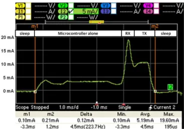
To illustrate the power consumption of the PowWow platform, Fig. 3 shows a power-supply current measurement obtained with an Agilent N6705A power-supply analyzer with the N6762A module connected to the PowWow node during a wake up followed by a wireless transmission. The measurement is taken after the DC/DC converter so that its yield does not interfere. In Fig. 3, several phases of the wireless protocol are evident. Outside the M1 and M2 markers, the node is in sleep mode and the current measured on the 200 µA caliber of the N6762A module is 27 µA. After M1 the microcontroller awakes and the current increases to 3.6 mA. The 19.6 mA peak current corresponds to a short wireless receive mode phase before the wireless transmission at 10 mA. The energy consumed for a signal transmission is therefore 5.19 mA×4.5 ms×3.3 V = 77 µJ. Considering one packet sent every second and by adding the power consumption in sleep mode, the energy consumed by the PowWow system every second is 166 µJ and the average power consumption is 166 µW. Those power
10 consumption measurements do not include the DC/DC yield loss. The LTC61031 have a quiescence current of 20 µA with an efficiency of around 90%. The energy consumption including the DC/DC converter therefore is then 240 µJ. When the PowWow node is disabled, the power supply is cut-off and the energy consumption of the node is negligible.
Figure 3. Power-supply current consumption measurement on PowWow node.
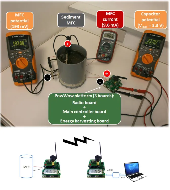
The sediment-MFC as the powering source of the PowWow system was connected as shown in Fig. 4 (top).
11
Figure 4. Top: Sediment-MFC powering the PowWow system. Vout varies between 1.7 V and 3.3 V and is
provided by the LTC3108 voltage step-up converter and Cout (Cf. Figure 3). Bottom : Schematic of the communication system with node A (left) powered by the MFC and node B (right) powered via the USB link.
The communication system is described in Fig. 4 (bottom). The node A is powered by the MFC. When the PowWow part of this node is enabled a Vout monitoring is effected with an embedded Analog-Digital-Converter (ADC). Then the Vout value is sent to the node B
12 (powered by USB) which adds a timestamp and sends this information (the Vout value and the corresponding timestamp) to a laptop via an rs232/USB translator.
3.2 Polarization curve
After stable performances were obtained (ca. 3 months) the sediment MFC was characterized by polarization and power curves (Fig. 5) according to the procedure detailed in the experimental section.
13 The maximum power output obtained was 2.5 mW (power density of 312.5 mW m-2) corresponding to a current of 7.9 mA (current density of 987.5 mA m-2) and potential of 0.32 V. This is equivalent to an internal resistance of 40 Ω which is very close to the value obtained considering the slope of the curve E vs. i calculated to be 39 Ω. The different contributions to the internal resistance (i.e. ohmic drop through the electrolyte, overpotential of electrode reactions and mass transfer resistance) have not been studied further in the context of this work but can be clarified as detailed in reference [27]. A satisfactory power density of ca. 300 mW m-2 was obtained (with respect to the projected surface of the cathode, 80 cm2). Those performances are of the same order of magnitude to those reported in other studies. Values from 170 to 665 mW m-2 [28-30] have been reported for sediment-MFC using Pt as a catalyst for the oxygen reduction reaction. An example of high performance MFC has been reported by Dong et al. [31] with power production higher than 800 mW m-2. In their study, no cathode catalyst was used but an efficient cathode design based on rolling activated carbon and polytetrafluoroethylene (PTFE). The advantage of our setup is the coupling of satisfactory fuel cell performances with simple materials (no artificial catalysts, no additional pre-treatment or modification of commercial carbon electrodes and no membrane or separator). Although the performances of our sediment-MFC are acceptable, they are not to be compared directly to related MFCs with different designs. Indeed, the architecture of an MFC is very important for optimizing power generation. [28]
It is important to stress that the current delivered by the functional sediment-MFC is stable in time, as shown in Fig. 6. As maximum power output was obtained for a potential close to 0.3 V, chronoamperometry was performed at this voltage (Fig. 6). In the first 20 minutes the current rapidly decreases from 30 to 5.5 mA (or 3750 to 687.5 mA m-2) because of charge accumulation in the anode biofilm at open-circuit and higher initial fuel concentration in the anode diffusion layer. For longer times, the near steady state current is rather stable and only
14 exhibits small variations comprised between 5.5 and 6.6 mA (or 687.5 and 825 mA m-2). This is assigned to temperature changes during measurement that directly affect microbial metabolism and/or oxygen solubility.
Figure 6. Chronoamperometry of MFC at 0.3 V during more than 4 days. Inset: focus on current variations
during time.
The MFC behavior displayed in Figure 6 indicates that a continuous powering of the electronic device may only be possible during the short time after connection during which the delivered current is high. When the current is stabilized to a lower value the intermittent enabling/disabling of the energy consuming node would still allow the radio transmission of signals. At the same time this would leave the MFC recover and/or permit the storing of the excess energy in the capacitor. This strategy is demonstrated next and has been previously used in the literature; see reference [13] for example.
15
3.3 Sediment-MFC as power supply
Once the MFC had shown stable performances, it has been connected to the PowWow system discussed above. Fig. 7 (top) shows the values of the node potential (Vout) as a function of time. Each point corresponds to a signal received by the node B. The first zone (1) in Fig. 7 (top) indicates that the energy delivered by the MFC is sufficient for powering continuously the wireless package. After 100 minutes, zone (2), Fig. 7 (top), the energy supplied by the MFC is not enough to sustain a continuous operation and the PowWow system works in degraded (intermittent) mode. Contrary to the continuous operation, a signal is not sent every second because the system is intermittently disabled to recharge the Cout capacitor.
16
Figure 7. Top: Node voltage of the wireless system powered by sediment-MFC. Each point corresponds to a
signal. Bottom: Detailed view of the node voltage as a function of time
This phenomenon can be observed very well in Fig. 7 (bottom) where the first phase corresponds to the continuous operation and the second to the alternate operation. During the alternate operation one can observe the disable period during which the Cout capacitor is recharging and the enable period where the Vout is decreasing due to energy consumption. Fig. 7 (bottom) also shows the 1.7 V lower limit of the capacitor threshold for the operating mode. The 2.9 V higher threshold is not observed because there is a voltage collapse as the PowWow systems is switched on. The last acquisition before disabling and the first one after enabling are not valid because the power supply of the microcontroller is not stabilized yet.
The experiment has been carried out during more than five hours, resulting in the sending of 8814 signals which correspond to a 53 % efficiency (100 % efficiency is equivalent to one signal sent per second during the whole experiment).
17 Those data indicate that the sediment-MFC was able to support the load of the wireless system and that it is possible to operate with lower frequency of message sending on much longer time frames.
4. Conclusion
Experiments have shown that the sediment-MFC was able to power the PowWow system for several hours and thus without any external control on the system.
During a first phase, the system received enough energy from the MFC to send one signal per second. In a second phase, even with lower energy, the PowWow system still allows the radio-transmission of signals at a slightly lower frequency. Depending on the targeted application (for example temperature or conductivity measurements), this mode may be suitable for many self-powered on-site monitoring applications.
It would be interesting to use this power source for longer times. This could be done by mean of a power management system which tracks the maximum power point [15,32] or by intermittent connection of the MFC [13] with the integration of a switch between the MFC and the RCup board.
Future work will deal with the modification of the card electronics in order to monitor external parameters such as temperature, pH or conductivity. Moreover, this could be carried out in real conditions such as outdoor parameters measurements during several days or months.
18
Acknowledgments
The authors thank the European Union for partly supporting this research with the European Union’s Seventh Framework Programme FP7/2007–2013 under Grant Agreement No. 226532, Joseph Le Lannic for SEM experiments, Dr. Sylvain Giraudet for B.E.T. measurements and MAST Carbon for supplying the carbon materials.
List of references
[1] L. Lapinsonnière, M. Picot, F. Barrière, ChemSusChem 5 (2012) 995–1005.
[2] B.E. Logan, Microbial Fuel Cells, John Wiley & Sons, Inc., Hoboken, NJ, 2008, pp. 4. [3] F. Harnisch, U. Schröder, ChemSusChem 2 (2009) 921–926.
[4] Z. He, H. Shao, L.T. Angenent, Biosensors Bioelectron. 22 (2007) 3252–3255.
[5] L.M. Tender, S.A. Gray, E. Groveman, D.A. Lowy, P. Kauffman, J. Melhado, R.C. Tyce, D. Flynn, R. Petrecca, J. Dobarro, J. Power Sources 179 (2008) 571–575.
[6] I. Ieropoulos, J. Greenman, C. Melhuish, Int. J. Energy Res. 32 (2008) 1228–1240. [7] F. Zhang, L. Tian, Z. He, J. Power Sources 196 (2012) 9568–9573.
[8] A. Shantaram, H. Beyenal, R. Raajan, A. Veluchamy, Z. Lewandowski, Environ. Sci. Technol. 39 (2005) 5037–5042.
[9] C. Donovan, A. Dewan, D. Heo, H. Beyenal, Environ. Sci. Technol. 42 (2008) 8591–8596. [10] D.R. Lovley, Microbe 1 (2006) 323–329.
[11] P. Aelterman, K. Rabaey, H.T. Pham, N. Boon, W. Verstraete, Environ. Sci. Technol. 40 (2006) 3388– 3394.
[12] C. Dumas, A. Mollica, D. Feron, R. Basseguy, L. Etcheverry, A. Bergel, Electrochim. Acta 53 (2007) 468– 473.
[13] A. Dewan, C. Donovan, D. Heo, H. Beyenal, J. Power Sources 195 (2010) 90–96. [14] F. Grondin, M. Perrier, B. Tartakovsky, J. Power Sources 208 (2012) 18−23. [15] J.-D. Park, Z. Ren, J. Power Sources 205 (2012) 151–156.
19 [17] H. Wang, J.-D. Park, Z. Ren, Environ. Sci. Technol. 46 (2012) 5247–5252.
[18] J.-D. Park, Z. Ren, IEEE T. Energy Conver. 27 (2012) 715–724.
[19] D. Dondi, A. Bertacchini, D. Brunelli, L. Larcher, L. Benini, IEEE T. Ind. Electron. 55 (2008) 2759–2766. [20] W. Seah, Z.A. Eu, H.-P. Tan, Proc. 1st Int. Conf. Wireless Commun., Veh. Technol., Inf. Theory Aerosp. Electron. Syst. Technol. (2009) 1–5.
[21] O. Berder, O. Sentieys, Proc. of the Workshop on Ultra-Low Power Sensor Networks (WUPS), co-located with Int. Conf. on Architecture of Computing Systems (ARCS 2010), 2010, Hannover, Germany, pp. 229–233. [22] O. Sentieys, O. Berder in: Wiley-ISTE (Eds), Energy Autonomous Micro and Nano Systems, Optimizing Energy Efficiency of Sensor Networks, 2012, pp. 325–360.
[23] S. Brunauer, P. H. Emmet, E. Teller, J. Am. Chem. Soc. 60 (1938) 309–314.
[24] M. Picot, L. Lapinsonnière, M. Rothballer, F. Barrière, Biosens. Bioelectron. 28 (2011) 181–188. [25] INRIA, TECH . PROJECT, « PowWow, Protocol for Low Power Wireless Sensor Network », http://powwow.gforge.inria.fr/ 2010.
[26] O. Sentieys, O. Berder, P. Quemerais, M. Cartron, Workshop on Design and Architectures for Signal and Image Processing (DASIP’07), 2007, Grenoble, France.
[27] A. Ter Heijne, O. Schaetzle, S. Gimenez, F. Fabregat-Santiago, J. Bisquert, D. P. B. T. B. Strik, F. Barrière, C. J. N. Buisman, H. V. M. Hamelers, Energy Environ. Sci., 4 (2011) 5035–5043.
[28] L.P. Huang, L.L. Gan, N. Wang, X. Quan, B.E. Logan, G.H. Chen, Biotechnol. Bioeng. 109 (2012) 2211– 2221.
[29] M.D. Yates, P.D. Kiely, D.F. Call, H. Rismani-Yazdi, K. Bibby, J. Peccia, J.M. Regan, B.E. Logan, ISME J. 6 (2012) 2002–2013.
[30] M. Ghasemi, M. Ismail, S.K. Kamarudin, K. Saeedfar, W.R. Wan Daud, S.H.A. Hassan, L.Y. Heng, J. Alam, S.-E. Oh, Applied Energy 102 (2013) 1050–1056.
[31] H. Dong, H. Yu, X. Wang, Q. Zhou, J. Feng, Water Research 46 (2012) 5777–5787.
[32] J.J. Guzman, K.G. Cooke, M.O. Gay, S.E. Radachowsky, P.R. Griguis, M.A. Chiu, Proc SPIE 7666:76662 M A (2010).