A NUMERICAL INVESTIGATION OF THE SEISMIC RESPONSE OF
TAILINGS IMPOUNDMENTS REINFORCED WITH WASTE ROCK
INCLUSIONS
BEHNAM FERDOSI
DÉPARTEMENT DES GÉNIES CIVIL, GÉOLOGIQUE ET DES MINES ÉCOLE POLYTECHNIQUE DE MONTRÉAL
THÈSE PRÉSENTÉE EN VUE DE L’OBTENTION DU DIPLÔME DE PHILOSOPHIAE DOCTOR
(GÉNIE MINÉRAL) DÉCEMBRE 2014
ÉCOLE POLYTECHNIQUE DE MONTRÉAL
Cette thèse intitulée:
A NUMERICAL INVESTIGATION OF THE SEISMIC RESPONSE OF TAILINGS IMPOUNDMENTS REINFORCED WITH WASTE ROCK INCLUSIONS
présentée par : FERDOSI Behnam
en vue de l’obtention du diplôme de : Philosophie Doctor a été dûment acceptée par le jury d’examen constitué de :
M. SILVESTRI Vincenzo, Ph. D., président
M. JAMES Michael, Ph. D., membre et directeur de recherche M. AUBERTIN Michel, Ph. D., membre et codirecteur de recherche M. LI Li, Ph. D., membre
DEDICATION
ACKNOWLEGEMENTS
I would like to express my special appreciation and thanks to my advisors Prof. Michael James and Prof. Michel Aubertin, you have been tremendous mentors for me. I would like to thank you for encouraging my research. Your advice has been priceless.
A special thanks to my family. Words cannot express how grateful I am to my mother and father for all of the sacrifices that they’ve made on my behalf. I would like to thank my brother-in-law, Farzad, for his support during my studies in Canada. I would also like to thank all of my friends who supported me during my studies, especially Pejman Nekoovaght and Vahid Marefat. I would like to express appreciation to my beloved wife Vila for her unyielding support and sacrifice during my studies in Iran and Canada. I would also like to thank my lovely daughter Rozhina whom I could not spend more time with during my studies, she is a marvel and lights up my life.
RÉSUMÉ
La fréquence de rupture des digues de parcs à résidus miniers est beaucoup plus élevée, par un facteur de 10, que celle des ouvrages de retenue d’eau conventionnels, avec 2 à 3 événements majeurs se produisant annuellement surtout le monde. Une des conséquences de ces ruptures (avec brèche) est l’écoulement de résidus liquéfié. Ces écoulements (ou épanchements) sont responsables de pertes de vie, de dommages à l’environnement et de coûts financiers considérables; ils représentent à cet égard un des principaux risques liés aux opérations minières. Les résidus miniers produits par les mines en roches dures sont particulièrement susceptibles à la liquéfaction (i.e. un perte quasi-complète de résistance due à un chargement dynamique ou statique), pouvant alors causer une rupture (p. ex. durant un séisme) ou être une conséquence de la rupture (p. ex. suite à une défaillance de la fondation qui réduit le confinement).
Aubertin et al. (2002b) ont proposé d’ajouter des inclusions de roches stériles dans les parcs à résidus, conjointement avec la déposition des rejets de concentrateur, afin d’améliorer leur performance environnementale et géotechnique. La roche stérile est ainsi placée de façon à créer des inclusions continues le long des orientations prédéfinies dans le parc. Il a alors été postulé que ces inclusions pourraient induire divers bénéfices, notamment en accélérant la consolidation des résidus et en agissant comme renforcement pour mieux résister aux sollicitations statiques et sismiques.
James (2009) a réalisé une série d’essais cycliques en cisaillement simple sur des résidus miniers, sur une gamme de contraintes de confinement et de contraintes en cisaillement cycliques. Il a ensuite montré que le modèle constitutif UBCSAND (Beaty and Byrne 1998) pouvait bien représenter le comportement dynamique de ces résidus. James (2009; voir aussi James et Aubertin, 2010, 2012) a aussi utilisé un modèle numérique pour simuler la réponse sismique d’un parc à résidus miniers conceptuel, construit sans et avec des inclusions de roches stériles (IRS). Ces résultats ont montré que de telles inclusions pouvaient grandement améliorer la réponse sismique de ce parc à résidus.
Un des essais cycliques en cisaillement simple réalisé par James (2009) sur des résidus miniers a été simulé avec le modèle UBCSAND (version of 904aR). Les résultats présentés ici, dans cette
thèse, indiquent que le modèle simulé bien les déformations en cisaillement, la génération des pressions interstitielles en excès, et la liquéfaction induites par de telles conditions.
A l’étape suivante, la capacité du modèle UBCSAND, implanté dans le code numérique FLAC (Itasca, 2008), a été évaluée pour simuler le comportement sismique des résidus miniers soumis à des essais sur un table sismique, tels que menés par Pépin et al. (2012a, 2012b). Deux de ces essais (nos. 3 and 7) réalisés sur des résidus seuls et avec un mur de sable ont été simulés. Les résultats de ces modélisations numériques ont montré que le modèle UBCSAND peut prédire correctement la génération de pressions interstitielles dans des résidus soumis à de tels essais, avant ou sans inclusion.
Les parcs à résidus miniers peuvent aussi céder après un événement sismique, en raison de la dissipation des surpressions en excès. Pour représenter ce comportement de façon réaliste, il faut reproduire la consolidation post-sismique (avec dissipation des surpressions). Deux approches ont été utilisées ici pour modéliser cet aspect. La première consiste à ajouter un cap (Vermeer, 1980) au modèle UBCSAND (version 904aR). Le modèle ainsi modifié a été utilisé pour simuler des essais (fictifs) de compression isotrope et œdométrique, et pour analyser la liquéfaction de résidus déposés en surface. Des résultats encourageants ont été obtenus, mais le modèle avec un cap a conduit à des instabilités numériques (possiblement dues à une singularité sur la surface limite). Une autre approche a alors été considérée. Avec cette seconde approche, les valeurs des modules élastiques des résidus miniers ont été mises à jour sur la base de la courbe de consolidation de résidus lâches. Cette approche combine la méthode proposée par Sento et al. (2004) avec le modèle UBCSAND, ce qui permet de reproduire le comportement post-sismique avec le tassement de résidus et la dissipation des surpressions. Les simulations ont alors montré que cette approche prédit correctement les tassements observés lors des essais sur table sismique. Cette approche a aussi été appliquée au cas du tassement post-sismique des dépôts du sable et de résidus en surface, et les résultats concordaient bien avec ceux obtenus de la relation empirique proposée par Wijewickreme et Sanin (2010).
Après ces vérifications relatives aux simulations du comportement sismique et post-sismique des résidus miniers, le modèle UBCSAND a été utilisé pour simuler numériquement le comportement d’un parc à résidus (basé sur le cas d’un site minier situé au Nouveau-Brunswick), auquel on a ajouté des inclusions de roches stériles. Le parc avec diverses configurations
d’inclusions a été soumis à des sollicitations sismiques, avec divers niveaux d’énergie et fréquences dominantes. Les résultats de ces analyses numériques ont montré que le parc à résidus (sans inclusions) pouvait subir des déformations excessives et une rupture sous les chargements sismiques considérés. Les résultats des simulations du parc renforcé ont montré que les inclusions de roches stériles pouvaient réduire considérablement les déformations de la pente aval et ainsi prévenir une rupture. La réponse du parc a aussi été évaluée sur la base de déplacements horizontaux moyens normalisés (ARx), le long de la pente aval et pour les IRS
seules. La performance du parc à résidus pour différentes configurations des inclusions (largeur et espacement) a été classifiée sur la base de ces valeurs du ARx à la fin du chargement cyclique.
Des graphiques montrent la valeur du ARx (globale et pour les IRS) en fonction de la largeur
totale des inclusions, pour diverses configurations. Ces résultats indiquent que dans la majorité des cas, les événements sismiques de basse fréquence produisent des déformations plus grandes que ceux de haute fréquence.
Les effets des IRS sur la réponse d’un parc à résidus ont été analysés numériquement pour le cas d’un autre site minier (situé au Québec). La réponse sismique a de nouveau été évaluée sur la base de la valeur du ARx (globale et des IRS) et aussi en fonction du volume de résidus subissant un déplacement critique, pour diverses configurations d’inclusions. Ces résultats montrent comment les IRS peuvent être adaptées pour améliorer la réponse sismique des parcs à résidus. Ces simulations illustrent une approche pour en arriver à une optimisation de la conception des IRS placées dans un parc à résidus, en fonction de sollicitations sismiques particulières.
ABSTRACT
The rate of failure of tailings impoundments is much larger, by a factor of about 10, than that of conventional water retention dams, occurring at a rate of about 2 to 3 per year worldwide. A primary consequence of the failure of a tailings impoundment is the flow of liquefied tailings. Such flows have been responsible for considerable loss of life, environmental damages and economic costs and represent one of the major risks associated with mining. Tailings, specifically those from hard rock mines, are particularly susceptible to liquefaction (a significant loss of shear strength) that can cause failure of the retention dyke and the release of liquefied tailings. Tailings liquefaction can be induced in dynamic loads, such as earthquakes, or static loads, such as dyke raising, erosion (loss of confining stress) or foundation movement.
Aubertin et al. (2002b) considered placing waste rock in tailings impoundments in tandem with tailings deposition to improve the environmental and geotechnical performance of the impoundments. The waste rock would be placed to create relatively narrow, continuous inclusions along planned routes in the impoundment. It was postulated that these waste rock inclusions would provide a number of benefits, particularly by accelerating the consolidation of the tailings and acting to reinforce the impoundment with respect to static and seismic loads. James (2009) conducted a series of cyclic simple shear tests on tailings over a range of confining stresses and cyclic stress ratios. Then, using numerical simulations, he showed that the UBCSAND model (Beaty and Byrne 1998) can predict well the cyclic behavior of tailings. James (2009) used numerical analyses to simulate the seismic response of a conceptual tailings impoundment with and without waste rock inclusions. It was shown that the use of such waste rock inclusions (WRI) could considerably improve the seismic response of an impoundment. One of the cyclic simple shear tests performed by James (2009) on tailings was simulated using the UBCSAND model (version of 904aR). The results of the simulation, presented in this thesis, indicate that the model can represent well the shear strain, excess pore water pressure generation, and initiation of liquefaction under these conditions.
In the next step, the capability of the UBCSAND model, as implemented in FLAC (Itasca, 2008), to simulate the seismic behavior of tailings in seismic table tests was evaluated using tests conducted by Pépin et al. (2012a, 2012b). The two tests (Nos. 3 and 7) were conducted on lightly
tamped tailings without and with a sand wall inclusion. The results of modeling showed that the UBCSAND model can predict fairly well the generation of excess pore water pressure in seismic table testing of tailings with and without an inclusion.
Tailings impoundments may fail after earthquake shaking due to the dissipation of excess pore water pressures. To model this phenomenon realistically, one can simulate post-shaking consolidation (excess pore water pressure dissipation). Two approaches were used to do so. In the first approach, a cap (Vermeer, 1980) was added to the UBCSAND model (version 904aR). The modified model was tested by simulating hypothetical isotropic compression tests, oedometer tests and level ground liquefaction of tailings. Reasonable results were obtained, but the UBCSAND model with a cap developed some mathematical instabilities (possibly due to a singularity on the yield surface). Therefore, another approach was used. In this second approach, the values of the elastic moduli of the tailings were updated in the model based on the consolidation curve of loose tailings. This approach combines the Sento et al. (2004) methods and the UBCSAND model to predict the post-shaking settlement of tailings due to pore water pressure dissipation. The simulations showed that this approach can predict well post-seismic settlement in seismic table testing.
The capability of this model to simulate the post-shaking settlement of level ground liquefaction in tailings was also compared with the empirical relationships of Wijewickreme and Sanin (2010) and the results were encouraging.
After verifying that the UBCSAND model can simulate the seismic and post-seismic behavior of tailings, the seismic response of a tailings impoundment (based loosely on an actual site located in New Brunswick), with and without waste rock inclusions was simulated numerically. The impoundment with various configurations of inclusions was subjected to earthquake loads of various energy contents and with different predominant frequencies. The results of the numerical analyses showed that the tailings impoundment without waste rock inclusion undergoes excessive deformation and failure under the seismic loads considered. The results of simulations with inclusions showed that WRI can significantly decrease the deformation of the downstream slope and prevent failure of the impoundment. Additionally, the response of the tailings impoundment was evaluated based on the average normalized horizontal displacements (ARx) of
different configurations of WRI (width and center-to-center spacing) was classified based on the ARx values at the end of shaking. Graphs that show the ARx (total and WRI) values as a function
of the total width of different configurations are presented. These graphs can be used to obtain (preliminary) optimum configurations of WRI for the seismic loads considered. The results also indicate that in most cases, the low frequency ground motions produce significantly more deformation than the high frequency ground motions.
The effect of WRI on the seismic response of a tailings impoundment was further evaluated using numerical simulations of another tailings impoundment (based on a mine site in western Quebec, Canada). The seismic response of the tailings impoundment was again evaluated using ARx (total and WRI) and the critically displaced volume of tailings at the end of shaking, for
different configurations of the inclusions. The results show how the WRI configuration can be adapted to enhance significantly the seismic response of tailings impoundments. These simulations provide preliminary guidelines for the optimum design of WRI placed in tailings impoundments for the seismic loads considered.
TABLE OF CONTENTS
DEDICATION ... iii ACKNOWLEGEMENTS ... iv RÉSUMÉ ... v ABSTRACT ... viii TABLE OF CONTENTS ... xiLIST OF TABLES ... xvi
LIST OF FIGURES ... xviii
LIST OF SYMBOLS AND ABBREVIATIONS ... xxii
LIST OF APPENDICES ... xxxi
INTRODUCTION ... 1
Objectives ... 2
Scope and content ... 3
CHAPTER 1: LITERATURE REVIEW ... 6
1.1 Mine waste ... 6
1.1.1 Tailings ... 6
1.1.2 Waste rock ... 7
1.1.3 Waste water ... 8
1.2 Management of mine wastes ... 8
1.2.1 Tailings management ... 9
1.2.2 Waste rock management ... 12
1.3 Environmental and geotechnical concerns of tailings impoundments ... 13
1.3.1 Environmental concerns and solutions ... 13
1.3.2 Geotechnical stability concerns ... 14
1.4 Hydro-geotechnical properties of hard rock tailings and waste rock ... 17
1.4.1 Hydro-geotechnical properties of hard rock tailings ... 18
1.5 Dynamic behavior of tailings and waste rock ... 22
1.5.1 Shear modulus, and dynamic damping ... 22
1.5.2 Pore water pressure generation due to cyclic loading ... 34
1.5.3 Liquefaction ... 38
1.5.4 Post liquefaction strength of soils ... 41
1.6 Evaluation of liquefaction resistance of granular soil ... 46
1.6.1 Cyclic stress approach... 47
1.6.2 Cyclic strain approach... 62
1.7 Methods for improving the seismic stability of tailings impoundments ... 63
1.7.1 An overview ... 63
1.7.2 Stone columns and gravel drains ... 64
1.7.3 Waste rock inclusions ... 67
1.8 Methods of seismic analysis of tailings impoundments ... 70
1.8.1 Pseudostatic analysis ... 70
1.8.2 Permanent-displacements methods ... 72
1.8.3 Stress-deformation analysis ... 73
1.9 Constitutive models for the numerical modeling of dynamic behavior of tailings ... 75
1.9.1 UBCSAND model ... 75
CHAPTER 2: ORGANIZATION AND OUTLINE ... 86
CHAPTER 3: ARTICLE 1-NUMERICAL SIMULATION OF THE SEISMIC AND POST-SEISMIC BEHAVIOR OF TAILINGS... 90
3.1 Introduction ... 91
3.2 Validation of the UBCSAND model based on laboratory testing ... 93
3.3 Updating of the shear and bulk moduli based on the consolidation curve ... 95
3.4.1 Material properties ... 97
3.4.2 Boundary conditions ... 100
3.4.3 Simulation results during shaking ... 101
3.4.4 Post-shaking settlement ... 102
3.5 Post-liquefaction settlement of a level ground model ... 102
3.5.1 Geometry and boundary conditions ... 103
3.5.2 Material properties ... 103
3.5.3 Simulation results... 103
3.6 Discussion ... 105
3.6.1 Alternative model with a cap ... 105
3.6.2 Limitations and ongoing work ... 106
3.7 Conclusion ... 106
3.8 Acknowledgements ... 107
3.9 References ... 108
CHAPTER 4: ARTICLE 2- EFFECT OF WASTE ROCK INCLUSIONS ON THE SEISMIC STABILITY OF AN UPSTREAM RAISED TAILINGS IMPOUNDMENT: A NUMERICAL INVESTIGATION ... 115
4.1 Introduction ... 116
4.2 Review of related work ... 118
4.3 Methods of Analysis ... 120
4.4 Characteristics of the NBM Tailings Impoundment ... 121
4.5 Simulations of the impoundment response ... 122
4.5.1 Constitutive Models of Material Behavior ... 123
4.5.2 Combined effective stress-total stress approach for post shaking analysis ... 125
4.5.4 Damping parameters ... 128
4.5.5 Earthquake ground motions ... 131
4.6 Static numerical analysis of the tailings impoundment ... 134
4.7 Dynamic numerical analysis of the tailings impoundment ... 134
4.7.1 Dynamic analyses of the impoundment without inclusions ... 135
4.7.2 Dynamic analyses of the reinforced tailings impoundment ... 135
4.7.3 Performance and classification of the reinforced tailings impoundment... 136
4.7.4 Post-shaking analyses of the reinforced impoundment ... 139
4.8 Complementary analyses and discussion ... 140
4.8.1 Effect of the frequency content ... 140
4.8.2 Effect of the WRI configuration ... 142
4.8.3 Consolidated tailings ... 146
4.9 Conclusion ... 146
4.10 Acknowledgements ... 147
4.11 References ... 148
4.12 Appendix ... 158
CHAPTER 5: ARTICLE 3- INVESTIGATION OF THE EFFECT OF WASTE ROCK INCLUSIONS CONFIGURATION ON THE SEISMIC RESPONSE OF A TAILINGS IMPOUNDMENT... 161
5.1 Introduction ... 162
5.2 Methods of analysis and evaluation ... 164
5.3 The tailings impoundment ... 164
5.4 Numerical modeling of the tailings impoundment ... 165
5.4.1 Constitutive models ... 165
5.4.3 Material properties ... 166
5.4.4 Damping parameters ... 167
5.4.5 Seismic loads ... 168
5.5 Seismic analysis of the unreinforced tailings impoundment ... 170
5.6 Seismic analysis of the impoundment with waste rock inclusions ... 171
5.6.1 Effect of ground motion intensity and frequency ... 177
5.6.2 Effect on the WRI configuration on the critically displaced volume of tailings .. 182
5.6.3 Effect of inclusions configuration on the performance of the tailings impoundment ………187
5.7 Complementary remarks ... 191
5.8 Conclusion ... 191
5.9 Acknowledgements ... 192
5.10 References ... 193
CHAPTER 6: SUMMARY AND GENERAL DISCUSSION ... 199
CONCLUSION AND RECOMMENDATIONS ... 208
REFERENCES ... 212
LIST OF TABLES
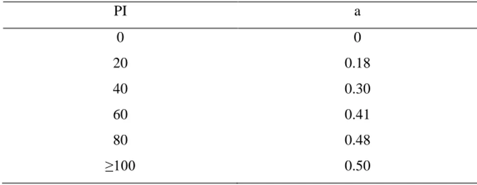
Table 1.1: Parameter ‘a’ for various values of the plasticity index PI (after Hardin and Drenvich, 1972) ... 24 Table 1.2: Estimation of K2, max for sand (after Seed and Idriss, 1970b) ... 25 Table 1.3: Values of Gmax/Su (for clayely soils) where Su is undrained shear strength (after
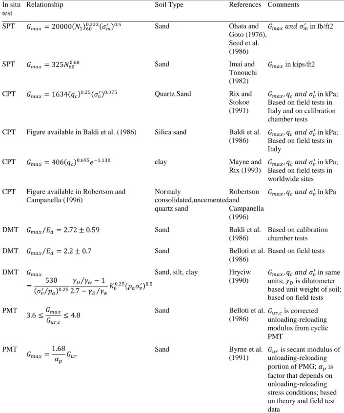
Weiler, 1988) ... 25 Table 1.4: Constants A, n in proposed empirical equation (1.10) for the small strain modulus (after Kokusho, 1987) ... 27 Table 1.5: Empirical relationships between Gmax and in-situ test parameters (after Kramer, 1996)
... 29 Table 1.6: Constants in proposed empirical formulae of initial shear modulus for gravels, eq. 1.10 (after Ishihara, 1996) ... 30 Table 1.7: Values of (after Hardin and Drnevich, 1972) ... 33 Table 1.8: Recommended Fines Correction for Estimation of Residual Undrained Strength by Seed-Harder and Stark-Mesri Procedures (after Kramer, 1996) ... 42 Table 1.9: Values of recommended by Seed (1987) (after Idriss and Boulanger, 2008) ... 46 Table 1.10: Values of CSR Correction Factor, cr (see eq. 1.37)(after Kramer, 1996) ... 50
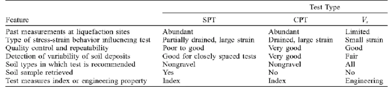
Table 1.11: Comparison of advantages and disadvantages of various field tests for assessment of liquefaction resistance (After Youd et al., 2001) ... 55 Table 1.12: Corrections to SPT (Modified from Skempton 1986) as listed by Robertson and Wride (1998) ... 59 Table 1.13: Magnitude scaling factor (MSF) values defined by various investigators (after Youd and Noble 1997) ... 61 Table 1.14: Summary of shaking table tests (after Pépin et al., 2012b) ... 69 Table 1.15: Summary of materials properties (after Pépin et al., 2012b) ... 69
Table 1.16: Results of pseudostatic analysis of earth dams that failed during earthquake (after
Seed, 1979) ... 71
Table 1.17: Pseudostatic coefficients from various studies (after Jibson, 2011) ... 72
Table 3.1: Summary of tailings characteristics for test 3 on the shaking table (after Pépin et al. 2012b) ... 98
Table 3.2: Input parameters used to simulate shaking table testing on tailings (test 3) ... 99
Table 3.3: Material properties of Bedrock and Glacial till (taken from James, 2009) for simulations of the tailings impoundment ... 104
Table 4.1: Hydraulic Conductivity of the different materials (after James and Leahy, 2010) ... 126
Table 4.2: Material properties (adapted from James 2009 and James and Leahy, 2010) ... 127
Table 4.3: Earthquake ground motion parameters ... 132
Table 5.1: Material properties (adapted from James 2009, Golder Associates 2011) ... 168
Table 5.2: Parameters of the base and modified ground motions ... 169
Table 5.3: Widths and spacing of waste rock inclusions ... 171
Table 5.4: Average normalized horizontal displacements (ARx) of the downstream slope of the impoundment (ARx total) and of the WRI (ARx WRI) for various inclusions configurations (modified Saguenay ground motions) ... 175
Table 5.5: Average normalized horizontal displacements (ARx) of the downstream slope of the impoundment (ARx total) and of the WRI (ARx WRI) for various inclusions configurations (modified Northridge ground motions) ... 176
LIST OF FIGURES
Figure 1-1: Common types of raised embankments; a) upstream-raised impoundment b) downstream-raised impoundment c) centerline-raised impoundment (modified from Vick, 1990) ... 10 Figure 1-2: Shear moduli from CSS testing (data grouped by consolidation stress) and G/GMAX
curves from Seed et al. (1984) for mean effective stresses of 25, 50, 100, and 200 kPa (modified after James, 2009) ... 32 Figure 1-3: Typical cyclic triaxial compression test results on a sample of contractive sand (a) axial strain versus number of cycles (b) excess pore water pressure versus number of cycles (modified after Holtz and Kovacs, 1981) ... 35 Figure 1-4: Typical cyclic triaxial compression test results on a sample of dilative sand (a) axial strain versus number of cycles (b) excess pore water pressure versus number of cycles (modified after Holtz and Kovacs, 1981) ... 36 Figure 1-5: Relationship between residual strength and corrected SPT resistance. (modified after Seed and Harder, 1990)... 43 Figure 1-6: Number of equivalent uniform stress cycles, Neq, for earthquakes of different
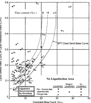
magnitudes (Richter) (modified after Seed et al., 1975) ... 48 Figure 1-7: SPT Clean-Sand base curve for magnitude 7.5 earthquakes with data from liquefaction case histories (taken from Youd et al., 2001- modified from Seed et al., 1985) ... 56 Figure 1-8: (a) Stress ratio history showing loading, unloading, and reloading (after Beaty and Byrne, 2011). (b) Incremental stress ratio versus plastic shear strain for cone mechanism for UBCSAND904a. (c) Incremental stress ratio versus plastic shear strain for cone mechanism for UBCSAND904aR ... 79 Figure 1-9: Example of predicted shear stress beneath upstream shell of Success Dam using UBCSAND version 904a (modified after Beaty and Byrne, 2011)... 80 Figure 1-10: Soil element and equivalent fluid models (modified after Puebla, 1999) ... 84
Figure 3-1: (a) Shear strain versus number of cycles for a CDSS (cyclic direct simple shear test) test on tailings, and FLAC modeling, (b) Shear stress versus shear strain for a CDSS test on tailings, and FLAC modeling, (c) Development of the excess pore water pressure ratio, ru (ratio
of excess pore water pressure to initial effective stress), during CDSS testing and simulation ... 94 Figure 3-2: Comparison between the measured consolidation curve and the curve given by the by Sento et al. (2004) model ... 98 Figure 3-3: Boundary conditions imposed to the model and piezometric measurement locations ... 100 Figure 3-4: The results of the generated excess pore water pressure measured (test 3) and predicted by the UBCSAND model, considering a small value of stiffness proportional damping for zones in which shear strain is less than 0.015% ... 101 Figure 3-5: Geometry and boundary condition of the FLAC model used to seismic analysis of level ground condition ... 103 Figure 3-6: Variation of excess pore water pressure ratio ru with time during seismic loading in
the bottom, middle, and top of the model (P1, P2, and P3 points as shown in Figure 3-5) for level ground using UBCSAND ... 105 Figure 4-1: Typical section of the NBM tailings impoundment with the external dyke ... 122 Figure 4-2: Cross section of the tailings impoundment with WRI a) schematic cross-section with locations of some points on the surface of the impoundment were simulations results are extracted; b) a typical cross section of tailings dyke reinforced by WRI ... 123 Figure 4-3: Shear modulus reduction curves for gravel soil presented by Rollins et al. (1998) (blue curve) and calculated by FLAC (red curve) for waste rock ... 130 Figure 4-4: Damping ratio curves for gravel soil presented by Rollins et al. (1998) (blue curve) and calculated by FLAC (red curve) for waste rock. ... 130 Figure 4-5a: Earthquake ground motion E3-sag based on the S16T record, Mw=7.0; PGA=0.295g
(see Table 4.3) ... 133 Figure 4-6: Distribution of pore water pressures in the impoundment under static condition ... 134
Figure 4-7: Horizontal displacements iso-contours (m) in the tailings impoundment due to E3-sag
earthquake record (Mw=7.0 and d=30 km) ... 135
Figure 4-8: Positions of the WRI in the reinforced tailings impoundment, with a width of W= 12 m and center-to-center spacing S= 42 m... 136 Figure 4-9: Horizontal displacements iso-contours (m) in the reinforced tailings impoundment (with WRI) for W= 12 m and S= 42 m, E3 earthquake record (Mw=7.0, d=30 km) ... 136
Figure 4-10: The average horizontal nodal velocities (Xvel) along the external dyke slope at the
end of shaking versus the average normalized horizontal displacement (ARx) for different
combinations of widths W and center-to-center spacings S of the WRI (see details in Table 4.A), the definitions of “stable” and “unstable” are defined in Section 4.7.4. ... 140 Figure 4-11: Values of Rx at different locations X (and height) along the external slope of the
tailings dyke due to E1 earthquake record. At top right: the first number is the width W (m) of the
inclusions, the second number is the center-to-center spacing S (m); “s” and “n” identify the high (Saguenay) and low (Northridge) frequency ground motions, respectively. ... 141 Figure 4-12: Average normalized horizontal displacements ARx of the external slope of the dyke
for reinforced impoundments versus total widths of the WRI placed in the tailings , for different local width and spacing (Mw=6.5) (a) E1-sag, (b) E1-north ground motions ... 143
Figure 4-13: Average normalized horizontal displacements ARx of the external slope of the dyke
for reinforced impoundments versus total widths of the WRI placed in the tailings , for different local width and spacing (Mw=7.0) (a) E3-sag, (b) E3-north ground motions ... 145
Figure 5-1: Cross section of the external dyke after three construction steps ... 164 Figure 5-2: Model of the tailings impoundment used for the numerical simulations ... 166 Figure 5-3: Final deformed geometry and horizontal displacements contours due to the E4-sag
ground motion (after 32 seconds) ... 170 Figure 5-4: Final deformed geometry and horizontal displacements contours due to E4-north
ground motion (after 25 seconds) ... 171 Figure 5-5: A typical model cross section of the tailings impoundment reinforced by WRI, having widths, W, of 12 m and a spacing, S, of 36 m ... 172
Figure 5-6: Final deformed geometry and horizontal displacement contour due to the E4-north
ground motion (at end of shaking) in the reinforced tailings impoundment (with WRI) for W=12 m and S=36 m ... 172 Figure 5-7: Distribution of the pore water pressure ratio (ru) due to E4-north earthquake record (at
end of shaking) in the reinforced tailings impoundment (with WRI) for W=12 m and S=36 m 173 Figure 5-8: Normalized horizontal displacements ARx for impoundments with 8-meter-wide
inclusions (a) E4-sagground motions (b) E5-sag (calculation was stopped for center-to-center
spacing of 64 m due to bad geometry error after 33 seconds) ... 180 Figure 5-9: Normalized horizontal displacements ARx for impoundment with 8-meter-wide
inclusions (a) E4-northground motions; (b) E5-north ... 181
Figure 5-10: Delineation of the zone of the impoundment that is displaced more than 100 cm at the end of seismic loading, for the E4-sag and E4-north ground motions and various WRI configurations, (a) WRI width of 8 m; (b) WRI width of 12 m; (c) WRI width of 16 m; (d) WRI width of 20; (e) WRI width of 25 m ... 184 Figure 5-11: Average of normalized horizontal displacements of the downstream slope of the tailings impoundment (ARx total) and of the WRI (ARx-WRI) as function total width of the inclusion, for different configurations (width, spacing) and modified ground motions (a) E4-sag, (b) E5-sag (c), E4-north, and (d) E5-north ... 189
LIST OF SYMBOLS AND ABBREVIATIONS
Symbols
area of the hysteresis loop maximum horizontal acceleration
ah horizontal pseudostatic acceleration
av vertical pseudostatic acceleration
non-dimensional parameters elastic bulk modulus (kPa)
elastic bulk modulus fluid bulk modulus
Ccr
compression index (-) recompression index
CN factor to normalize Nm to a common reference effective overburden stress
(kPa)
CE correction for hammer energy ratio
CB correction for the borehole diameter
CR correction for rod length
CS correction factor for samples with and without liners
normalizing factors for cone penetration resistance correction factor
D closest horizontal distance to the fault rupture (km) relative density
size of grain that 10% of the grains by weight are smaller that
D50 grain size of 50% passing by mass
E Young’s modulus
e void ratio
initial void ratio (-)
̅ rebound modulus
F yield function
f frequency of applied load
G shear modulus
secant shear modulus tangent shear modulus
specific gravity
maximum shear modulus
secant modulus of unloading-reloading low amplitude shear modulus
elastic shear modulus ID density Index
Ix Arias intensity in x horizontal direction (m/s)
Iy Arias intensity in y horizontal direction (m/s)
elastic bulk modulus (kPa)
Ke coefficient represents elastic absorption (-) saturated hydraulic conductivity
coefficient of lateral stress shear modulus coefficient ( ) constant
ratio of effective vertical stress to effective horizontal stress initial shear stress correction factor
initial normal stress correction factor horizontal coefficient of permeability vertical coefficient of permeability elastic shear modulus number (-) elastic bulk modulus number (-) plastic modulus number
ksat saturated hydraulic conductivity (m/s)
logarithmic strain (-)
N number of applied stress cycles Nl cumulative number of cycles required
( ) corrected number of blows in SPT test Nm measured standard penetration resistance
modulus exponent (-) modulus exponent (-)
coefficient of volume compressibility
coefficient of volumetric compressibility (1/kPa) mp plastic bulk modulus exponent
Mw moment magnitude
n porosity
P exceedance probability PI plasticity Index
atmospheric pressure (kPa) preconsolidation pressure
existing effective vertical overburden pressure mean effective stress (kPa)
cone penetration tip resistance
shear strength under steady state
stress reduction factor RF failure ratio
undrained shear strength
steady sate shear strength
post cyclic maximum shear strength
effective confining stress (kPa) maximum shear stress (kPa)
Ts fundamental period of the sliding mass
excess pore water pressure generated by the cyclic shear stress Vs shear wave velocity
overburden-stress corrected shear wave velocity limiting upper value of
dissipated energy maximum strain energy
exponent (-)
dry unit weight
density
drained friction angle cohesion
unit weight of water dynamic viscosity shear stress
shear strain
maximum effective principal stress intermediate effective principal stress minor effective principal stress
octahedral shear stress
mean principal effective stress
shear strain at peak point of loading loop vertical effective stress
maximum damping ratio
damping ratio
excess pore water pressure shear stress increment normal stress increment
minor effective consolidation stress
threshold shear strain effective confining stress
angle of flow liquefaction surface
initial static shear stress effective vertical stress effective horizontal stress
cyclic shear stress cyclic shear strain
volumetric strain
standard normal cumulative distribution function incremental plastic strain
total stress component
increment of plastic strain { } state of stress
{ } vector of total effective stress increment { } incremental total stress
normal stress dilation angle
stress ratio
incremental volumetric strain incremental shear strain
constant volume friction angle
Poisson’s ratio stress ratio at failure friction angle at failure developed friction angle
developed stress ratio
incremental plastic volumetric strain incremental plastic shear strain
developed friction angle scalar plastic multiplier initial plastic shear modulus
normalized initial plastic shear modulus cone mechanism hardening parameter increment of major plastic strain increment of minor plastic strain
cap pressure
plastic modulus number stress ratio (-)
volumetric strain increment (-) dry density
friction angle (°)
initial vertical effective stress (kPa)
mean effective stress (kPa) effective vertical stress (kPa) angle of dilation
Abbreviations
ARx average normalized horizontal displacement of downstream slope of
tailings impoundment CPT cone penetration test CSR cyclic stress ratio CRR cyclic resistance ratio CSL critical state line
CDSS cyclic direct simple shear test DMT dilatometer test
FC epwp
fine content
excess pore water pressure FLS flow liquefaction surface MSF magnitude scaling factor
Mxdis maximum horizontal displacement of downstream slope of impoundment OCR over consolidation ratio
PGA peak ground acceleration PMT pressuremeter test SPT standard penetration test
LIST OF APPENDICES
APPENDIX A- THE UBCSAND MODEL WITH CAP ... 246 APPENDIX B- NUMERICAL MODELING OF SEISMIC TABLE TESTING OF TAILINGS WITH AND WITHOUT INCLUSION ... 252 APPENDIX C-THE RESULTS OF NUMERICAL SIMULATIONS OF A TAILINGS IMPOUNDMENT BASED (LOOSELY) ON A MINE SITE IN NEW BRUNSWICK, CANADA ... 267 APPENDIX D- THE RESULTS OF NUMERICAL SIMULATIONS OF A TAILINGS IMPOUNDMENT (BASED ON A SITE LOCATED IN THE WEST OF QUEBEC, CANADA) ... 316
INTRODUCTION
Hard rock mining produces two primary types of quasi-solid waste: waste rock and tailings. These wastes often contain contaminants such as heavy metals and chemical agents used in ore processing. If they contain sulphides, they may also produce acid mine drainage. The safe disposal of tailings, which exceed the mass of the extracted economically-viable minerals by factors varying from about 4 for iron ore typical quality to 1,000,000 for gold, is a primary concern for the mining industry. During the last 50 years, more than 30 tailings impoundments have failed as a result of seismic activity, causing significant loss of life as well as environmental and economic damage (ICOLD 2001; Aubertin et al. 2002b; WISE 2104). Therefore, the evaluation of the seismic stability of tailings impoundments and methods of improving their seismic stability are priorities.
Stone (gravel) columns may be used in naturally occurring soils to either prevent liquefaction or control its effects (Sasaki and Tanighuchi, 1982; Barksdale et al. 1983; Ledbetter, 1985; Sonu et al., 1993; Adalier et al., 2003). In sands, liquefaction may be prevented by the dissipation of excess pore water pressures through the vertical columns as they are generated during earthquake shaking. Additionally, the rigid columns provide reinforcement that reduces shear strains and thus deformation and the tendency for excess pore water pressure generation. In silts, the drainage effect of the columns during earthquake shaking is negligible due to the relatively low hydraulic conductivity of such fine-grained soils. However, the reinforcement effect results in a stiffer response that can reduce the rate of generation of excess pore water pressure during earthquake shaking and significantly reduce deformation, while helping to dissipate the pressures after the event.
Expanding on this concept, Aubertin et al. (2002a) suggested a new co-disposal method involving waste rock and tailings. In this method, waste rock is placed inside of tailings (waste rock inclusions) to improve the seismic stability of tailing impoundments. Aubertin et al. (2002b) theorized that the addition of waste rock inclusions in tailings impoundments would increase the consolidation rate of the tailings during deposition (as confirmed by Jaouhar et al., 2011, 2013; L. Bolduc and Aubertin, 2013, 2014) and provide shear resistance to static and dynamic loads.
James (2009) conducted numerical analyses of the behavior of a conceptual tailings impoundment without and with waste rock inclusions subjected to a range of earthquake loadings. The simulations were conducted with version 5 of the FLAC finite difference software program (Itasca, 2006). The elasto-plastic Mohr-Coulomb model was used to simulate the behavior of the waste rock inclusions and the UBCSAND model (version 904a; Beaty and Byrne 1998) was used to simulate the behavior of the tailings. The applicability of the model to tailings was verified through numerical simulations of cyclic simple shear testing of the tailings. The analysis showed that the presence of waste rock inclusions resulted in a significant improvement in seismic performance and in some cases prevented failure of the impoundment.
Pépin et al. (2012a, 2012b) used seismic table testing to evaluate the effect of rigid, draining, or rigid-draining inclusions on the dynamic behavior of tailings. The testing demonstrated the ability of such inclusions to reduce the rate of excess pore water pressure generation and deformation.
Despite these preliminary results, some gaps and uncertainties remain; these can be summarized as follows
Capabilities of available constitutive laws have not been evaluated to predict the seismic response of tailings submitted to complex loading conditions, as in seismic table tests.
The available models usually cannot predict correctly the post seismic settlement of tailings due to pore water pressure dissipation.
The seismic response of an actual tailings impoundment has only been evaluated partially, and many important situations and conditions have not yet been assessed.
The effect of seismic loads on critically displaced volumes of tailings has not been evaluated nor used to assess the response of impoundments.
There is no guideline to optimize the design of waste rock inclusions in tailings impoundment with respect seismic response.
Objectives
Verifying and calibrating the UBCSAND model for the simulation of the pore water pressure generation during seismic table tests performed on tailings by Pépin et al. (2012a, 2012b).
Developing the required FISH routine(s) to allow the UBCSAND model to better represent the tailings behavior post-shaking, specifically the volumetric plastic strains due to isotropic compression or when the loading direction is on or parallel to yield surface or in direction that does not intersect the yield surface (as when tailings are consolidating during the dissipation of excess pore water pressures after shaking). “FISH” is an internal programming language used in the finite difference code FLAC (Itasca, 2008) which is used here for the numerical simulations.
A numerical investigation of the seismic response of two tailings impoundments with and without waste rock inclusions, based (loosely) on their general characteristics and considering critical seismic loadings.
Determining the effect of waste rock inclusion configuration on the seismic performance of the subject tailings impoundments.
Developing a path to preliminary guidelines for the design of tailings impoundments reinforced with waste rock inclusions with respect to seismic stability.
Scope and content
Chapter 1 of this thesis reviews the state of art and practice literature review. It contains:
A description of wastes produced by hard rock mining and waste disposal methods.
Geotechnical concerns related to tailings impoundments, specifically regarding seismic stability.
A summary of the hydro-geotechnical properties of tailings and waste rock.
Description of the dynamic behavior of tailings and waste rock.
An overview of methods for improving the seismic stability of tailings impoundments.
Constitutive models for the numerical modeling of the dynamic behavior of tailings.
Numerical modeling of conceptual tailings impoundment reinforced with waste rock inclusion.
Chapter 2 presents the organization and outline of the thesis. It also explains the connections between the different chapters and briefly describes their content; this thesis mainly consists of three papers submitted to peer-reviewed journals.
Chapter 3 presents numerical simulations of the seismic and post-seismic behavior of tailings, conducted with FLAC (Itasca, 2008). It describes the numerical simulations of cyclic simple shear tests and seismic table tests performed on tailings using the UBCSAND model version 904aR (Beaty and Byrne, 2011). In this chapter, a new approach is introduced for simulating the post-liquefaction behavior of tailings due to excess pore water pressure dissipation. In this approach, the modulus of tailings is updated based on the consolidation curve of loose tailings. Chapter 4 presents a numerical investigation of the effects of waste rock inclusions on the seismic stability of an upstream-raised tailings impoundment. The seismic response of an actual tailings impoundment without and with waste rock inclusions was targeted here, based loosely on the site conditions at a tailings impoundment located in New Brunswick, Canada. In situ data such as CPT, SPT and shear wave velocity were used to estimate the properties of the tailings. The simulations have been performed for unconsolidated and consolidated tailings. The results of unconsolidated tailings are presented in this chapter and the results obtained for consolidated tailings are presented in Appendix C.
Chapter 5 presents the results of an investigation of the effect of waste rock inclusions on the seismic response of a tailings impoundment located in the Abitibi region of Quebec, Canada (but with conditions somewhat different than those at the mine site). The UBCSAND and Mohr-Coulomb elasto-plastic models were used respectively to simulate the tailings and waste rock (with FLAC). The effects of frequency content and intensity of the seismic loads and of the inclusions configuration on the deformation of the downstream slope of the impoundment and critically displaced volume of tailings were investigated in this chapter. Preliminary guidelines for optimizing waste rock inclusions with respect to the applied seismic loads are also included in this chapter.
Chapter 6 presents a summary and a general discussion with the limitations of this research. Finally the main conclusions of this research are recalled and recommendations for further research are presented.
Additional details on the dynamic numerical simulations of tailings impoundments conducted for this research are presented in the appendices.
1
CHAPTER 1: LITERATURE REVIEW
The seismic stability of tailings impoundments is a concern. During the last 50 years, more than thirty tailing impoundments have failed as a result of seismic activity, particularly due to tailings liquefaction (ICOLD 2001; Aubertin et al. 2002b; WISE 2014).
Aubertin et al. (2002b) suggested the use of waste rock inclusions to increase the seismic stability of tailings impoundments. Afterwards, James (2009), James and Aubertin (2010, 2012), and Pépin et al. (2012a, 2012b) investigated the behavior and stability of tailings and tailings impoundments with inclusions, experimentally and numerically. The results of these studies indicate that the presence of waste rock inclusions can improve the seismic performance of tailings impoundments and retard and/or reduce the excess pore water pressure generation in tailings during the seismic loading.
Although comprehensive research has been done to model a conceptual upstream-raised tailings impoundment reinforced with waste rock inclusions (James, 2009), an actual upstream-raised impoundment reinforced with the waste rock inclusions has not been simulated numerically. Guidelines for the design of tailings impoundments with waste rock inclusions have not yet been proposed. This project aims at using comprehensive dynamic numerical modeling to achieve these goals. Additionally, the above-mentioned results identified certain limits of the UBCSAND model (Naesgaard, 2011) which will be addressed as part of this work.
This chapter summarizes a literature review on the seismic stability of tailings impoundments without and with waste rock inclusions, and reviews some using existing constitutive models.
1.1 Mine waste
1.1.1 Tailings
Separating valuable minerals from ore produces a concentrate of the valuable minerals and tailings, a slurry containing fine particles of crushed rock of no economic value. Vick (1990) classifies tailings into four categories; soft-rock tailings, hard-rock tailings, fine tailings, and coarse tailings, based on their geological origin and general engineering behavior:
Soft-rock tailings are derived from fine coal refuse, trona, and potash among others. They are combinations of fines (particles less than 0.075 mm) and sands (particles between 0.075 mm and 4.75 mm) with the fines portion often called “slimes” being a greater portion of the mass and highly active (plastic). The engineering behavior of soft rock tailings is thus dominated by slimes and is somewhat similar to that of plastic silt or clay.
Hard-rock tailings are produced from base and precious metals such as lead-zinc, copper, gold-silver, molybdenum, and nickel. Hard-rock tailings are combinations of sand and slime where the slimes are nonplastic and overall behavior of these types of tailings is characterized by inter-granular friction with little or no cohesion.
Fine tailings are produced from phosphatic clays, bauxite red muds, taconite, and slime from oil sands mines among others. These types of tailings consist mainly of fines and their engineering behaviors, such as the sedimentation-consolidation, are comparable to those of highly plastic clays.
Coarse tailings are produced from tar sands, uranium, gypsum, coarse tactonite, and phosphate mines. They are mostly composed of sand-sized particles with little fines and behave similarly to coarse-grained sands.
This research is focused on hard rock tailings. However, many of the findings may be applicable to other types of tailings as well.
Hard rock tailings particles may contain significant concentrations of sulphide minerals such as pyrite, pyrrhotite, and arsenopyrite (Aubertin et al., 2002a; Bussiere, 2007) as well as trace metals. The presence of these substances may be problematic from an environmental viewpoint as described later in this document.
1.1.2 Waste rock
Extraction of ore in a mining operation requires that rock be excavated, either in an open pit or an underground mine, to reach the ore body or to provide service openings. This excavated material is known as “waste rock” and has no economic value. Waste rock typically consists of angular particles of rock varying from sand to boulder in size. The maximum particle size, typically 0.5 to 1.0 m, is determined by the characteristics of the parent rock (i.e. fractures and
joints), the method excavation (i.e. blasting method and pattern) and, in underground mines, the need to transport the waste rock to the surface for disposal.
According to Aubertin et al. (2002a), the ratios of dry weight of waste rock to tailings in Canada for open-pit and underground mines are about 9:1 and 3:1, respectively.
As with tailings, waste rock from hard rock mines may contain significant concentrations of sulphide minerals such as pyrite, pyrrhotite, and arsenopyrite (Aubertin et al., 2002a; Bussiere, 2007) as well as trace metals. Waste rock from hard rock mines tends to consist of hard, angular particles. The durability of the particles is variable; waste rock particles containing sulfides may be subject to physical degradation due to chemical reactions.
1.1.3 Waste water
The mineral extraction process often includes crushing and grinding of the ore and the addition of water to facilitate chemical extraction or to create flowable slurry for transport of the ore resulting particles through the plant. Once the valuable minerals are extracted, the resulting waste may be divided into tailings slurry and waste water that may contain chemicals used in the ore extraction process or metals leached from the rock particles.
1.2 Management of mine wastes
Mine wastes should be deposited and treated in a manner that avoids environmental damage and geotechnical instability. Selection of a suitable disposal area and design and construction of the disposal site should be included in the mine wastes management process. Wastes management is one the most important aspects of mining and of geotechnical engineering because mine wastes can create various environmental and geotechnical problems. Many publications on mine wastes management have been issued by different researchers and practitioners such as Vick (1990), Aubertin et al. (2002a), and Bussiere (2007), Blight (2010). In the following sections, a brief review of the published works, specifically Bussiere, (2007) is recalled.
1.2.1 Tailings management
1.2.1.1 Conventional methods of tailings disposal
Tailings are usually transported as slurry and deposited in dedicated areas, called tailings impoundments (Bussiere, 2007). The impoundments are retained, partly or completely by dykes, and the natural topography. These impoundments may contain tailings and waste water. The location of tailings impoundments depends on different parameters based on geological, topographical, geotechnical, hydro-geological, environmental, and operational considerations. The materials used for the construction of the retention dykes are the tailings (coarse fraction), waste rock or borrow soils.
Most impoundments are constructed in stages. Typically, an initial stage capable of retaining the tailings deposition for the first few years of mine operation is constructed using a starter dyke composed of borrow material and subsequent stages composed of the coarse fraction of the tailings (or waste rock or borrow material) are added to increase the height of the dyke and the thus the capacity of the impoundment as needed. Three different methods are commonly used to raise the retention dykes; upstream, downstream, and centerline (Vick, 1990).
Figure 1-1: Common types of raised embankments; a) upstream-raised impoundment b) downstream-raised impoundment c) centerline-raised impoundment (modified from Vick, 1990)
1.2.1.2 Densified tailings
A vast majority of tailings are deposited hydraulically as slurry in tailings impoundments and allowed to consolidate under their own weight. As a result, the tailings may be highly susceptible to liquefaction and flow (in the event of a rupture of the retention dyke) which can lead to considerable adverse consequences (to be discussed later). Additionally, a significant quantity of water in the form of free water and pore water is stored in the impoundment.
To reduce the risk of liquefaction and flow of tailings and to reduce the water load of mining operations in areas of scarcity, tailings may be by the removal of a portion of the pore water prior to deposition. The technologies employed in the densification of tailings, thickened tailings, paste tailings and filtered tailings, offer interesting operational alternatives for tailings deposition and are described briefly below.
Thickened tailings
The thickened tailings (TT) method was proposed by Robinsky (1975) to reduce environmental risks associated with conventional tailings impoundments. The TT technology minimizes the requirement for retaining dykes and eliminates the pond formed on the surface of most impoundments by creating a self-supporting homogenous mass of tailings. In this method, the tailings are densified by thickeners to a solids content of 50% to 70%. Thickened tailings behave like a viscous fluid. The thickened tailings are discharged downhill into a valley or from a tower on flat terrain. The yield stress of these types of tailings is 10 to 300 Pa. The TT are relatively homogenous. The risk of stability problems associated with tailing impoundments is reduced. Desiccation in natural climatic conditions may increase consolidation and the strength of TT. These tailings are initially partially saturated and their susceptibility to liquefaction is not yet clear. In area with high levels of seismicity, stability of TT under seismic loading is of concern.
Paste tailings
Paste tailings (PT) are a mixture of tailings and water and occasionally a binding agent such as cement. Segregation usually does not occur in the dense tailings. Paste tailings are tailings that are thickened using a thickener and filter discs. A suitable paste is then made by adding water to achieve a solids content of 70% and 85% (Martin et al. 2006). Paste tailings create self-supporting homogenous tailings stacks that do not require retention dykes. The undrained shear strength of PT varies between 5 and 60 kPa and may be higher due to desiccation in arid regions. PT do not segregate during deposition; therefore tailings keep their homogeneity. Binders may also be added to PT to increase the shear strength and water-retention properties and decrease the hydraulic conductivity. There are, however, a number of uncertainties regarding the long term and seismic behavior of paste tailings.
Filtered tailing
Filtered tailings (FT) are produced using high pressure filters to increase the solids content to 80% to 90%. They form a cake that can be handled using conventional earth moving equipment (Davies and Rice 2001). FT have high in situ density and low water content. Therefore, their geotechnical characteristics are better than those of conventional (slurry) tailings.
The cost of filtering and transporting tailings are relatively high. However, in dry climatic regions, water recovery is important and is Artic climates, slurry transport is problematic. Therefore, uses of FT under these conditions lead to important advantages (Davies and Rice 2001).
1.2.1.3 Co-disposal of tailings and waste rock
Mine waste co-disposal is “the simultaneous or alternate deposition of tailings and waste rock in the same surface facility” (Bussiere, 2007). Co-disposal methods include: co-mixing, layering and waste rock inclusions in tailings impoundments. Co-disposal of mine wastes aims to achieve better properties relative to tailings alone.
Co-mixing
Waste rock and tailings can be combined prior to deposition. In this method the tailings fill the voids between the coarser waste rock. Co-mixing results in increased shear strength, lower hydraulic conductivity and improved water retention (Wilson et al. 2000, 2002, and 2003). Wickland and Wilson (2005) showed that co-mixing produces dense, high strength, and low hydraulic conductivity materials that are less prone to physical instability relative to conventional tailings. Application of this method in the field requires further study and research.
Layering co-disposal
Another method for co-disposal of tailings and waste rocks is to add layers of tailings within waste rock piles. Tailings layers may reduce oxygen flux and water infiltration (Lamontage et al. 1999; and Fala et al. 2003; Bussiere 2007). Although layering co-disposal reduces oxygen flux and water infiltration, it cannot completely eliminate the potential for acid mine drainage (AMD) (Bussiere 2007). Co-disposal by layering is also in the conceptual stage and more research is needed to evaluate its application in the field.
1.2.2 Waste rock management
As mentioned in section 1.1.2, waste rocks are commonly placed in purpose built waste rock piles. There are different methods of constructing waste rock piles: dumping, push dumping, free dumping, and drag line (Aubertin et al. 2002a). Waste rock piles are designed using different
configurations such as valley-fill, ridge, cross-valley, heaped, and side-hill to form, waste rock piles. Surface disposal of waste rock may cause environmental and geotechnical problems, such as acid mine drainage or instability (Aubertin et al. 2002a).
1.3 Environmental and geotechnical concerns of tailings impoundments
As mentioned in section 1.2, the most common method for managing tailings is to store them in surface impoundments. Environmental and geotechnical concerns should be considered in the design of tailings impoundments. Hard rock tailings are capable of producing acid (Aubertin et al., 2002a; Bussire, 2007) and may contain concentrations of heavy metals and chemicals used in ore processing. This is potentially dangerous for the environment. In addition to such environmental concerns, the geotechnical stability of tailings impoundments is another issue that is very important in their design and construction. According to Davies (2002), failure of tailings impoundments is ten times more likely than for water retention dams. Some of the environmental and geotechnical concerns are described in the following sub-sections.
1.3.1 Environmental concerns and solutions
As previously noted, hard rock tailings may contain significant concentrations of sulphide minerals such as pyrite, pyrrhotite, and arsenopyrite (Aubertin et al., 2002a; Bussiere, 2007) as well as trace metals. The exposure of sulphide minerals to oxygen and water can produce acid. The resulting acid mine drainage (AMD) is one of the primary environmental concerns for tailings impoundments. Bussiere (2007) reported different methods of preventing or reducing AMD:
Limiting water infiltration by the construction of a low saturated hydraulic conductivity cover. These covers are configured like those that have been developed for the isolation of domestic and hazardous wastes (Aubertin and Chapuis 1991; Daniel and Koerner, 1993; Rowe et al., 2004).
Covers utilising capillary barrier effects can be effective in limiting water infiltration in arid climates (Williams et al., 1997; Zhan et al., 2001; Alberight et al., 2004).
Another method for limiting AMD is submerging the tailings under water to prevent the entry of oxygen (Amyot and Vezina, 1997; Julien et al., 2004). This is a very common method.
Oxygen consuming materials such as wood waste, straw mulch, or other organic residues can be used as a cover to to consume oxygen in the air before it reaches the tailings (Tasse et al., 1997; Cabral et al., 2000).
Covers with capillary barrier effects can be used to create a low oxygen diffusion layer to limit oxygen migration (Nicholson et al., 1989; Aubertin et al., 1995; Bussiere et al., 2003).
Other environment contaminants in tailings are heavy metals in the water as well as residual compounds from ore processing, such as sodium cyanides used in gold extraction. Such heavy metals and chemical compounds can have adverse environmental impacts if released from the impoundments through seepage (or failure of the impoundment). If the foundations of the impoundment are not sufficiently impervious, a liner must be added to prevent groundwater contamination. The liner can be made from clay or a composite system.
1.3.2 Geotechnical stability concerns
From a geotechnical point of view, the design of tailings impoundments, specifically the retention dykes, is somewhat different from that of water-retention dams. According to CDA (2010), unique aspects of tailing dams that should be taken into account in geotechnical design include: the applied load from tailings on dam, an elevated phreatic surface, the potential for AMD, seepage pathways and internal erosion due to freezing or deterioration of decant pipes, and hydro-mechanical interactions with other infrastructure.
According to Davies (2002) there are more than 3,500 tailings dam worldwide. Several of these dams have experienced significant failure over the years. There were 238 reported of tailings dams failure between 1917 and 2014 (ICOLD, 2001; WISE, 2014). Some 26 of the 238 incidents were due to seismic loading. Based on ICOLD (1996a; 1996b), the five most frequent causes of failure of tailings dams are: slope of foundation instability, internal erosion, surface erosion, overtopping, and decantation structure malfunction.
Davies (2002), Davies et al. (2002a, 2002b) suggested that static liquefaction is frequently associated with tailings impoundment failure. Static liquefaction is the reduction of the shear strength due to increased pore water pressures (reached at steady state point). The conditions that can trigger of static liquefaction are (Davies et al., 2002b):
Increased pore water pressure as a result of a raised phreatic surface.
Rapid raising of the impoundment.
Loss of confinement (e.g. removal of toe due to overtopping, erosion, etc.).
Foundation failure that creates undrained loading in the tailings.
Tailings may also undergo liquefaction as a result of dynamic loading. This phenomenon is described in detail in Section X.
Notable failures of tailings impoundments around the world due to static of dynamically-induced liquefaction include:
Barahona tailings dam, a 61-meter-high structure, located at the El Teniente copper mine in Chile failed due to liquefaction during an earthquake with a magnitude of 8.2 in October 1928. Approximately 4 million tons of liquefied tailings were released as a result of the failure (Ishihara et al., 1980; ICOLD, 2001).
On March 28, 1965 multiple tailings dam failures occurred due to seismically induced liquefaction in northern Chile. Failure of the El Cobre tailings impoundment released 2 million tons of tailings and 200 lives were lost (Dobry and Alvarz, 1967; Davies and Lighthall, 2001; WISE, 2014).
In 1968, tailings dam failed in Hokkaido, Japan due to seismically induced liquefaction. The magnitude of earthquake was 7.9. Failure released 90,000 cubic meters of tailings that traveled 150 meters downstream (WISE, 2014).
In 1969 in Spain, a tailings dam failed after heavy rain due to static liquefaction. Failure released 115,000 cubic meters of tailings and caused major downstream damage and loss of life (WISE, 2014).
In 1970 in Mufulira, Zambia, a tailings impoundment failed due to static liquefaction and about 1 million tons of liquefied tailings were released. The tailings flowed into underground mine works and 89 miners lives were lost (WISE, 2014).
On 15 January, 1978 in Japan, two tailings dams failed due to seismically induced liquefaction. That released tailings severely damaged the environment downstream. The magnitude of the earthquake was 7 (Ishihara, 1984).
On 13 October 1980, in New Mexico, USA, a tailings dam failed due to static liquefaction. The dam was breached due to pore water pressure build up as a result of rapid raising of the dam. The failure released 2 million m3 of tailings. The tailings flowed 8 km downstream and damaged farmlands (WISE, 2014).
In March 1985, the Cerro Negro No.4 and Veta de Agua No. 1 Tailings Impoundments (Chile) failed during a magnitude 7.8 earthquake due to seismically induced liquefaction in Chile. The failures released 500,000 and 280,000 cubic meters of tailings, respectively, which flowed as much as 8 km downstream (WISE, 2014).
The Stava Tailings Dam in Italy failed on July, 1985. Approximately 240,000 m3 liquefied tailings were released. The tailings flowed at speeds of up to 60 km/h and destroyed the village of Stava and also caused some damages at the village of Tesero. The reason for failure was the decrease in effective stress due to an increase in the phreatic surface. The decreasing effective stress created a stress path that reached the failure surface triggering static liquefaction (Davies et al., 2002a).
A tailings impoundment at the Sullivan Mine in Canada failed due to static liquefaction on August of 1991. The dam was constructed on a foundation of older tailings. Shear strain increased after construction of dam resulting in increasing pore water pressure that led to static liquefaction. The failure was brittle and indications of liquefaction such as sand boils were observed on site (Davies et al., 2002a).
The Tapo Canyon tailings dam in southern California failed due to seismically induced liquefaction on 17 January, 1994 (Harder and Stewart, 1996).