HAL Id: tel-01665172
https://tel.archives-ouvertes.fr/tel-01665172
Submitted on 15 Dec 2017HAL is a multi-disciplinary open access
archive for the deposit and dissemination of sci-entific research documents, whether they are pub-lished or not. The documents may come from teaching and research institutions in France or abroad, or from public or private research centers.
L’archive ouverte pluridisciplinaire HAL, est destinée au dépôt et à la diffusion de documents scientifiques de niveau recherche, publiés ou non, émanant des établissements d’enseignement et de recherche français ou étrangers, des laboratoires publics ou privés.
Sintering of cerium oxide based materials by microwave
heating
Hussein Hammoud
To cite this version:
Hussein Hammoud. Sintering of cerium oxide based materials by microwave heating. Other. Université de Lyon, 2016. English. �NNT : 2016LYSEM004�. �tel-01665172�
NNT : 2016LYSEM004
THÈSE
Présentée par
Hussein HAMMOUD
Pour obtenir le grade de
Docteur de l’École Nationale Supérieure des Mines de Saint-Étienne
Spécialité : Science et Génie des Matériaux
Sintering of Cerium Oxide based materials by Microwave heating
Soutenue à Saint-Etienne, le 25 Mars 2016 Membres du jury
Rapporteurs : M. Jean-Marc CHAIX Mme Cristina LEONELLI
Directeur de Recherche au CNRS, SIMAP, Grenoble.
Professeur, Université de Modène et de Reggio d’Emilie, Modène, Italie Examinateur(s) : M. Sylvain MARINEL
M. Manuel POUCHON
Professeur, Université de Caen Basse- Normandie, Caen
Maître d'enseignement et de recherche, EPFL, Lausanne, Suisse
Directeur(s) de thèse : M. François VALDIVIESO Professeur, Ecole Nationale
Supérieure des Mines, Saint-Etienne Encadrant de thèse: M. Sébastien VAUCHER Chargé de Recherche au laboratoire
1
There are more possible roads to knowledge, but
scientific logic allows us to be wrong or right with
complete confidence.
This thesis is only a beginning of my journey.
2
Acknowledgments
I would like to acknowledge, the MeAWaT project and the Ecole des Mines of
Saint Etienne for funding this work.
I am grateful to Prof. François Valdivieso and Dr. Sébastien Vaucher for
recruiting me in carrying out this work. This research would not have been
complete without their guidance and support. I feel very lucky to have them. For
me, they have been a guide, a leader, and an example. Thank you.
Sincere thanks to the committee members, Prof. Jean-Marc Chaix, Prof.
Cristina Leonelli, Prof. Sylvain Marinel and Dr. Manuel Pouchon, for their
insightful questions and comments and their remarkable contribution in my
work.
My warm thanks go to all members of the laboratories LGF (Saint-Etienne,
France), SIMAP, (Grenoble, France), EMPA (Thun and Dübendorf,
Switzerland) and PSI (Villigen, Switzerland), for their help, support and
generous assistance during more than three years.
I owe special thanks to all of my friends in Lebanon, Switzerland and France for
their willingness to help me whenever needed. Thank you.
Finally, I am indebted to my ever loving parents and my sisters for their endless
support and patience. I love you.
3
Contents
Introduction ... 7
References ... 10
Chapter 1: Background ... 11
1.1 Interaction of electromagnetic radiation with matter and microwave heating ... 11
1.1.1 Interaction of microwave radiation with matter: ... 11
1.1.2 Dielectric materials: complex permittivity and loss tangent: ... 13
1.1.3 The main physical quantities of microwave-matter interaction: ... 14
1.1.4 Difference between direct and indirect/hybrid microwave heating. ... 16
1.1.5 Microwave generators and cavities (applicators): ... 17
1.1.5.1-Microwave generators: ... 17
1.1.5.2-Microwave cavities (applicators): ... 18
1.2 Solid state sintering ... 19
1.2.1 Definition: ... 19
1.2.2 Stages of sintering: ... 19
1.2.3 Basic principles and driving forces for sintering: ... 20
1.2.4 The influence of the powder properties on the sintering: ... 24
1.2.4.1-Grain size ... 24
1.2.4.2- Point defects ... 25
1.2.5 Activation energy and diffusion coefficient: ... 26
1.2.6 Experimental methods to determine the activation energy: ... 27
1.2.6.1- Constant heating rate (CHR) ... 27
1.2.6.2- Master sintering curve (MSC) ... 28
1.2.7 Microwave effects: ... 29
1.3 Cerium dioxide (ceria) ... 33
1.3.1 Structural and physical properties of ceria ... 33
1.3.2 Thermodynamic aspect ... 35
1.3.3 Defects and vacancies ... 35
1.3.4 Electrical conductivity ... 36
1.3.5 Studies concerning the sintering of ceria ... 37
1.4 Conclusion ... 40
Résumé en français : Généralités et bibliographie ... 41
4
Chapter 2: Dielectric and thermophysical characterisation methods ... 47
2.1 Preparation of ceria pellets by powder metallurgy ... 47
2.2 The dielectric measurement methods ... 49
2.2.1 Coaxial probe method: ... 49
2.2.2 Resonant cavity method ... 53
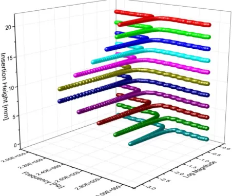
2.2.3 TM loaded empirical method ... 65
2.2.4 Back to the concept of the modes and the verification of the mode shifting in the cavity (TM loaded): ... 65
2.3 The thermal properties measurement methods: ... 68
2.3.1 The measurement of the thermal diffusivity by Laser Flash Analysis:... 69
2.3.2 The measurement of the specific heat capacity cp by Differential Scanning Analysis:. 69 2.3.3 The calculation of thermal conductivity: ... 71
2.4 Conclusion: ... 71
Résumé en français : Méthodes de détermination des propriétés thermo-physiques et diélectriques de la Cérine ... 72
References ... 73
Chapter 3: Dielectric and thermophysical properties of cerium dioxide ... 75
3.1 Characterization of the raw ceria powder ... 75
3.2 Microstructure for porous and dense materials by Scanning Electron Microscopy ... 76
3.3 Effective permittivity ... 79
3.3.1 Determination of the real part of dielectric constant 'r by coaxial probe method ... 79
3.3.2 Effective permittivity, Maxwell-Garnett model (taking into account the porosity) ... 81
3.3.3 Dependency of dielectric properties (real part) on porosity at room temperature ... 81
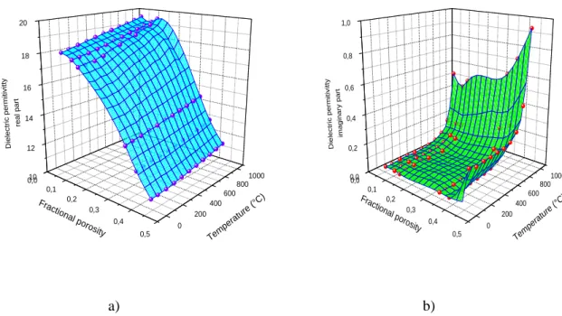
3.3.4 Dependency of dielectric properties on temperature and porosity ... 82
3.4 Thermal properties ... 84
3.4.1 Effective thermal conductivity, theoretical models of porosity dependence ... 85
3.4.2 Dependency of thermal properties on temperature and porosity ... 87
3.5 Conclusion ... 92
Résumé en français : Propriétés diélectriques et thermo-physiques du dioxyde de cérium (Cérine) .... 93
References ... 94
Chapter 4: Conventional and microwave sintering of cerium oxide ... 97
4.1 Preparation of ceria pellets from micro and nano powder ... 97
4.2 Conventional sintering method... 98
5
4.3.1 The setup ... 99
4.3.2 The materials used and the methods of measurement ... 102
4.4 The measurement of the density ... 107
4.4.1 The geometrical method ... 107
4.4.2 The density calculated from the shrinkage during the sintering ... 107
4.5 Experimental study: Conventional versus Microwave sintering ... 108
4.5.1 The densification curves of ceria ... 109
4.5.2 Comparison of the microstructures of sintered ceria samples ... 112
4.6 Conclusion ... 115
Résumé en français : Frittage de la Cérine par chauffage conventionnelle et par chauffage micro-ondes ... 116
References ... 117
Chapter 5: Microwave effect on model and ceria particles: a simulation study ... 119
5.1 The different concepts of model and the materials parameters ... 119
5.1.1 The physical scenario and the geometry... 120
5.1.2 The materials properties ... 123
5.1.3 The mesh ... 123
5.2 The electric field interaction with model particles ... 127
5.2.1 The effect of particle size ... 127
5.2.2 The effect of ’ and ’’ ... 129
5.3 The electric field interaction and the heating of three ceria particles without thermal losses 132 5.3.1 The effect of neck size ... 132
5.3.2 The effect of packing configuration ... 136
5.4 The electric field interaction and the heating of full ceria particles packing ... 139
5.4.1 The full packing in crucible ... 139
5.4.2 The effect of surface area and the compacting on the heating ... 141
5.5 Discussions ... 143
5.6 Conclusion ... 143
Résumé en français : Effet du champ micro-ondes sur des particules modèles et des particules de Cérine: une simulation multi-physique. ... 145
References ... 146
Conclusions ... 147
6
2 Future work ... 148 Appendix: QuickWave simulator ... 149 References ... 151
7
Introduction
Nowadays, the management of nuclear waste is one of the most important challenges and questions due to the increase of the nuclear production of energy. In the year 2000, the spent fuel being produced was about 220’000 tonnes and is growing by 10’000 tonnes each year (Greenpeace International). For example, there are over 435 commercial nuclear power reactors operable in 31 countries, its total capacity is about 375’000 MWe, and there are about 70 more reactors under construction. One solution is that radiotoxic nuclear wastes containing minor actinides (americium, curium and neptunium) can be recycled for usage in accelerator driven systems and can reduce the time to obtain the original uranium to 1000 years instead of 100’000 years. The figure 1 shows the production of nuclear power in 2013.
Figure 1: The nuclear power produced by some countries in 2013.
In order to transmute the actinides, different options exist. One of them is the production of conventional fuel pellets, which has the issue of a rather heavy use of mechanical devices and the production of powders. Other options are new types of fuel, such as particles, which offer a simplified fabrication route. Here the Sphere-Pac concept is promising. In order to produce fuel particles for this concept, three tasks should be carried out. Firstly, the dissolution of spent fuel in an aqueous reprocessing step, this leads to a nitrate solution containing the actinides. With that a feed solution containing the actinides and the chemical ingredients has to be produced, this will later allow a gelation process, where the spheres are formed. The chemical process here is the internal gelation, which is driven by a temperature increase. Secondly, the temperature increase is realised within a microwave cavity. Therefore the microwaves have to be transferred into the glovebox, which contains all the radioactive solutions, to perform the internal gelation technique for the production of the xerogel drops (spheres). Finally, the collected gelled spheres have to be sintered. A good option here is the
8
sintering by microwave heating in order to densify it at lower temperature with less loss of actinides due to the evaporation. These dense spheres will be filled together in the cylindrical cladding (pin), which results in the so called sphere-Pac fuel. The pins will then be used in the transmutation system, such as a conventional fast reactor, or a subcritical version, allowing higher minor actinide contents, called accelerator driven systems (ADS)
The process requires a controlled and dust-free environment. The aqueous route is ideal to fulfil this demand. Having reached the solid phase, after gelation and drying, when it comes to sintering, the treatment by microwave technology was recommended as a good candidate and a suitable technique. In the research on nuclear fuels, ceria is used as non-radioactive simulant for plutonium [1]. The synthesis of millimetric sphere shaped CeO2 xerogel particles (see
figure 2) by microwave assisted internal gelation has been studied [2]. The washing and the drying of the solution which is produced by the digestion of the nuclear wastes are the first stages for a complete process. Hence, the porous spheres produced must be further densified by microwave sintering. Several studies have investigated the use of microwave technology for the internal gelation at a frequency of 2.45 GHz [3-5].
Figure 2: The cerium oxide gelled spheres collected in water (Laboratory for Nuclear Materials, PSI).
Since the eighties, the elaboration of ceramics by microwave heating was the target of several studies in the area of ceramics.Microwave technology is currently used as an alternative route to conventional processing techniques in order to treat different kinds of materials. The sintering process of ceramics is one of the applications of microwave heating which in general has more advantages compared with conventional sintering technique, such as rapid heating process, uniform heating within the specimen which provides a homogenous physico- mechanical properties and its ability to modify the microstructure and the chemical reaction pathways due to its selective heating [6, 7].
Actually, the motivation of this thesis is mainly the evaluation of the use of microwave technology and its applicability in the densification step of this procedure and then following-up the sintering process of cerium oxide.
In addition, there is a major gap in understanding the gain provided by microwave sintering compared to conventional sintering. The studies found in literature concerning the sintering of ceria based materials didn’t include the microwave sintering of pure ceria. This gap presents a real challenge not only in the fundamental research area but also in industrial scale. Moreover, it is an additional reason that motivates us to contribute to this challenge. Hence, several objectives are integrated in thesis work to perform the task.
9
Firstly, the influence of the porosity for ceria up to 1000°C should be studied by determination of the thermal and dielectric properties of a series of model samples of ceria which were sintered conventionally in varying range of porosity.
Secondly, the ability of microwave sintering of ceria should be evaluated and compared to the conventional sintering.
Thirdly, the development of a setup which couples a classical furnace with microwave resonator using the cavity perturbation method for the determination of the dielectric properties of ceria at high temperature is necessary.
Finally, the experimental data should be introduced in Multiphysics solver in order to study the interaction of the electromagnetic field with ceria spheres and the temperature, guiding to understand the sintering process.
Given this current context, we have developed a system to determine the dielectric properties of ceria and made a comparison study between microwave sintering in single mode cavity and conventional sintering by a classical dilatometry for two different powder granulometry. In addition, a simulation study by COMSOL Multiphysics solver which couples electromagnetic and heat transfer and treats the different parameters of ceria as inputs has been included to this work in order to quantify the effect of electric field on the sintering.
This work has been funded by CCEM Project MeAWaT. A part of this work was made at the laboratory of Materials science and Technology (EMPA, Thun, Switzerland) in collaboration with Paul Scherrer Institute (PSI, Villigen, Switzerland). The other part of this work has been developed at the Ecole des Mines of Saint Etienne (Saint-Etienne, France) in collaboration with SIMAP laboratory (Grenoble, France).
This manuscript is structured in five chapters which are presented as follows:
- Chapter 1: is dedicated to the interaction of matter with electromagnetic radiation, the sintering basics, the properties of cerium oxide and some studies concerning its sintering.
- Chapter 2: is dedicated to the experimental setup developed for the determination of the dielectric properties of ceria and the different methods used for the determination of thermal and physical properties.
- Chapter 3: concerns the results of the thermal and dielectric properties of ceria and additional their connection with the rules of mixture (pores and matter).
- Chapter 4: presents the comparison study of sintering of ceria pellets by the two different techniques: conventional and microwave sintering. Moreover, the effect of particle size of the powder is also reported in this section.
- Chapter 5: is dedicated to the multiphysics simulation using COMSOL. The effect of different factors such as neck and particle sizes and the packing effect on the electric field are reported in this part to understand the electromagnetic effect on the sintering. Finally, the conclusions achieved through this thesis and some prospects for related future
10
References
[1] M.E. Huntelaar et al, The thermodynamic properties of Ce2O3 (s) from T= 0 K to 1500 K, J. Chem. Thermodynamics, 32, 465–482, 2000
[2] M.C. Sempere, Innovative production of nuclear fuel by microwave internal gelation, PhD thesis, Universitat Politècnica de València, 2013.
[3] A. Rosin, A. Schmidt, T. Gerdes, J. Somers and M. Porada, Microwave assisted internal gelation of droplets - a case study, InVerTec e.V. and Institute for Transuranium Elements and University of Bayreuth, Tech. Rep., 2005.
[4] S. Yamagishi, A new internal gelation process for fuel microsphere preparation without cooling initial solutions, Journal of Nuclear Materials, Vol. 254, 14-21, 1998.
[5] S. Yamagishi and A. Hasegawa, Method and apparatus for producing gel particles, U.S. Patent 5, 581-589, 1996.
[6] J. M. Osepchuk, A history of microwave heating applications, IEEE Transactions on Microwave Theory and Techniques 32, 1200-1224, 1984.
[7] D.E. Clark et al, Processing materials with microwave energy, Materials Science and Engineering A, 287, 153-158, 2000
11
Chapter 1: Background
1.1
Interaction of electromagnetic radiation with matter and
microwave heating
1.1.1 Interaction of microwave radiation with matter:
The microwave energy is an electromagnetic energy which has a range of frequencies between 300 MHz and 300 GHz, corresponding to wavelength range between 1 mm and 1 m. These waves are called also centimeter waves. Moreover, the typical frequencies used for the materials processing are: 0.915, 2.45, 5.8 and 24.125 GHz which are the industrial, scientific and medical radio bands (ISM). The typical frequency for microwave oven used by 90% of American homes is 2.45 GHz which is equivalent to a wavelength of 12.24 cm in free space. On the other hand, the microwave systems operated at 915 MHz are well used by the industrial and commercial market because the conversion of the electric power into electromagnetic power in these systems is higher than the conventional technique (the efficiency exceeds 82% instead of 70%). From the economical point of view, the microwave technology has been shown to reduce the cost and deliver a good performance comparing to the classical technique. The figure 1.1 shows the electromagnetic spectrum and their applications.
Figure 1.1: The electromagnetic spectrum (left) and the typical microwave and wireless applications (right) [1].
12
An electromagnetic wave consists of a magnetic wave which propagates perpendicularly to an electric wave. We are not interested in our study to the magnetic interaction with the
matter but only to the electric interaction with it.
When the electromagnetic (EM) waves encounter the matter, three possible behaviours (figure 1.2) can results:
1- If the electromagnetic waves are completely reflected, the material is opaque.
2- If the waves are transmitted through the matter without the loss in energy, the material is transparent.
3- If a fraction of the waves are absorbed, the material is an absorbent and will heat when an electromagnetic field exists. Hence, in the AC field at high frequency, the interaction between the EM field as photons and the matter composed of uncharged and charges particles such as ions (cations and anions) and electrons are the origin of a heating through the material. Actually, this mechanism is based on the interaction between the dipoles of the object and the electric field where the charges form induced dipole moments that tend to align with electric field in competition with thermal effects. On the other hand, if the system presents permanent dipole moments, the alignment of these dipoles is due to electrical torque and it is influenced by the thermal effects as well. Moreover, if the field is non-uniform, a field gradient will be presented and will cause the dielectrophoresis forces in the treated system [2]. These forces do not require charged particles and depend strongly on the electrical properties, shape and size of particles. In case of ceramics, the main factors that contribute to microwave heating are ionic and electrical conductivity, degree of porosity, particle size and point defects [3].
It is important to note that in case of metals, an electric current is created at the surface and therefore the majority of the energy is reflected and just a very small part will be absorbed by the metallic material whereas this energy is much more efficient for a ceramic material where the penetration depth (see the equation 1.7) is generally greater than the dimension of the material.
13
1.1.2 Dielectric materials: complex permittivity and loss tangent:
When the matter is exposed to an electric field excitation, it acts through an electric displacement fieldD. It is related to the electric field E by:
D
E
(Eq.1.1) where is the dielectric permittivity of the material.When the applied electric field is sinusoidal, D depends on the angular frequency and the permittivity of the material becomes complex . It can be written: *( )
* ' ''
( ) ( ) j ( )
(Eq.1.2)
where and '( ) are respectively the real part and the imaginary part of the ''( )
permittivity.
The real part of complex permittivity is related to stored energy within the material and the imaginary part to the dissipated energy within it. Thus, we can define a loss tangent ( tan ) as the ability of the matter to absorb the electromagnetic energy and to transform to heat energy. It is related to the dielectric losses and given by:
'' ' ( ) tan ( ) (Eq.1.3)
It is known that the heating of the material is better when its loss tangent is important. On the other hand, another mechanism associated to the electrical conductivity can be presented where the free charges create an electrical current and provide heat energy by Joule Effect. We can define the total dissipated factor
t'' as the sum of two contributions: the dielectric losses and the conductive losses.'' '' t (Eq.1.4) where is the electrical conductivity of the material.
14
In case of insulators such as ceramics, the dielectric losses have the main contribution on the total dissipated losses whereas in case of conductors (metals and semiconductors) the loss mechanism is associated to the conductivity.
It is important to note that in case of magnetic materials such as magnetite (Fe3O4), another
loss mechanism will present and contribute to the microwave heating process through its interaction with the magnetic field.
1.1.3 The main physical quantities of microwave-matter interaction:
The matter itself has specific elements which are the origin of the phenomenon. As we mentioned in the previous section, the free charges are related to the electrical conductivity and the fixed charges to the complex permittivity
*. These charges align by the action of the electric and/or magnetic field [5]. In the case of ceramic materials like CeO2, the absorption ofmicrowaves is low and due in general to the physical barriers such as the defects and the grain boundaries. Hence, these barriers can resist to the charge flow by generating the space charge [6].
The main parameters that describe and determine the uniformity and the efficiency of the heating by microwaves are:
1- The dissipated power P (W.m-3):
The quantity of the electromagnetic energy converted each second into heat energy per one cubic meter of a nonmagnetic material is given by Equation 1.5:
2 '' 0
(
2
)
P
f
E
(Eq.1.5)
where
id the electrical conductivity (S/m), │ E │is the electric field norm (V/m),f is the frequency of the radiation (Hz), 0 is the permittivity of free space and
'' is the loss factor or the imaginary part of the complex permittivity of the matter.2- The penetration depth d (m):
A part of the electromagnetic wave penetrates into material and transforms typically to heat energy. This heat energy decreases and is expressed by an attenuation factor
given by equation 1.6:
' 2 1 tan 1 2 2
(Eq.1.6)15
where is the wavelength of the radiation
'is the real part of the complex permittivity and tan is the loss tangent which is equal to'' '
.
The penetration depth is the distance at which the power becomes 1/e (about 37%) of its value at the surface. It is defined by the relationship with [7]:
2 tan 2 1 ' d (Eq.1.7) For a typical frequency of 2.45 GHz'' '
974
.
1
d
(cm) (Eq.1.8)For example, it is equal to 7 cm for SiC and 100 cm for Zirconia [8, 9]. The calculated value for ceria is about 13 m.
3- Thus in a unit of volume, the variation of the temperature per unit of time depends on the dissipated power and can be expressed as [10]:
2 '' 0 2 eff p f E T t C
(Eq.1.9)A several types of dielectric polarisation can exist during the interaction:
Electronic polarisation: it is presented for the majority of the frequencies and it is less efficient for very high frequency.
Ionic polarisation: this type of resonance is activated only in the infrared range of frequencies.
Dipolar polarisation: it is also called molecular polarisation and is created in general at low range of frequencies in the presence of an external electric field. It is typically the main contribution during the microwave heating.
Space charge polarisation: it requires very low frequencies and it is well known in physics of semiconductors.
Interfacial polarisation: this polarisation is presented only in case of heterogeneous materials.
16
The figure 1.3 presents the relaxation curves of Debye in order to show the dependence of the two parameters (the dielectric constant
'and the loss factor
'') on the frequency. It shows that the different dielectric polarisations become weak for high frequency. On the other side, the loss factor which is the main parameter for the dissipation of the electromagnetic energy in the matter, decreases when the frequencies are higher than the frequency range of the dipolar polarisation.Figure 1.3: The response of the dielectric constant (a) and the loss factor (b) in a large range of frequencies [11].
1.1.4 Difference between direct and indirect/hybrid microwave heating.
In order to get a good microwave heating, two ways of microwave heating can be used depending on the materials properties.
a- Direct heating: the principle of this heating is to put a sample (the target for heating) directly in microwave applicator (figure 1.4.a). Then, the result of the interaction between the microwave and the matter leads to the heating. In general, this type of
17
heating becomes more efficient at high temperature especially for a low absorbent material, such as the most of the ceramic materials.
b- Indirect heating: the principle of this heating is to use a good absorbent material (susceptor) which is exposed to microwave. Then, it is heated up and consequently heats the target material by infrared radiation (figure 1.4.b). This type of heating is similar to the conventional heating and is used in case of a transparent or low absorbent material.
Actually, a hybrid heating is an indirect one but in addition the sample becomes absorbent at a certain temperature, where the direct heating takes place.
Microwave heating had a success in the sintering field for a variety of ceramics, metals and composites materials. The difference between this technique and the conventional one resides in providing a volumetric heating, direct transfer of energy and rapid heating [12]. Comparing to the conventional heating, it reduces the energy consumption and time required; particularly for high temperature range where in general heat losses increase strongly with the temperature [13]. Hence, the microwave technique offers uniform heating that delivers better mechanical properties with lower environmental hazards, which are not observed in conventional treatment [5, 13].
Figure 1.4: Types of microwave heating
1.1.5 Microwave generators and cavities (applicators):
In the microwave processing field, it is known that the main tools for the microwave process are: microwave generators and microwave cavities.
1.1.5.1-Microwave generators:
Based on the applications [14], in general we can find four kinds of microwave sources and therefore four different generators:
18
a- Magnetron: it is a microwave source which is the most usable and has a range of frequency between 1 and 30 GHz.
b- Klystron: it is used as an amplifier for high frequencies (up to 100 GHz) and as oscillators for microwave relay but it is now limited for some applications such the modern particle accelerators.
c- Gyrotron: it was developed in 1958 by Twiss and Schneider [15] the advantage of this microwave source is its high power (1 MW) and its high frequency (up to 300 GHz). It is generally used for plasma heating.
d- Solid state generators: the invention of solid state transistors and its used in radios were the origin of the solid state microwave generators and it was proposed as a better alternative to the magnetrons. Its advantages are various comparing to magnetrons. It produces a very stable signal and it is operated at very low voltage. It has better shelf-life than magnetron and it is less noisy because the creation of microwave by solid state generators is based on the transistors instead of vacuum tubes in magnetrons. In addition, the solid state microwave has a range of frequencies whereas the magnetron has a fixed frequency [14].
1.1.5.2-Microwave cavities (applicators):
In order to optimize the energy produced by the generator and to get a better microwave absorption by the sample, a microwave cavity is required. It is metallic box which has special shape (most of them are rectangular) and dimensions. Depending on the dimensions, we can distinguish in general two main types:
a- Single mode cavity: the feature of a single mode cavity is that only one propagation mode is available in the frequency range selected. It is important to note that an empty cavity (unloaded) with canonical shape such rectangular or cylindrical, has an available exact analytical solutions for the electric and magnetic field. When loaded the analytical solution has to be redeveloped to take into account the influenced of loaded material (shape and material properties) [16-17]. It is used in general for homogeneous heating of sample smaller than 1/8 of the wave length. These applicators are used in general in the fundamental research domain.
b- Multimode cavity: in comparison to single mode cavity, a multimode cavity presents many propagation modes on a small frequency range delivered by solid state generator or at fixed frequency imposed by magnetron. The energy will be fed in the mode where the exciting frequency is matched. Consequently, when the sample has a large volume, more modes can be found therefore the heating becomes more efficient. Moreover, the distribution of the fields in this cavity is very complex which requires a wave stirrer in order to get a uniform electromagnetic field. These applicators are more used in industrial area where the amount of materials is important.
19
1.2
Solid state sintering
1.2.1 Definition:
The fabrication of ceramics by sintering process appears for a very long time about 12000 years ago (Jomon pottery in Japan) [18], it is considered as one of the oldest technique to make the ceramic components.
Solid state sintering in powder metallurgy is a process at a high temperature below the melting point that can elaborate a ceramic piece starting from the ceramic powder by bonding together its particles where the diffusion mass transport is activated. Hence, this process produces the ceramic components which have different microstructures such as porosities, grain size... It is not easy to find a simple definition of sintering but according to a definition given by Fang [19], the sintering is:
‘’A thermal treatment for bonding particles into a coherent, predominantly solid structure
via mass transport events that often occur on the atomic scale. The bonding leads improved strength and lower system energy’’.
1.2.2 Stages of sintering:
Based on the evolution of the microstructures during the sintering process, it is normally described through three stages:
a. Initial stage: this stage is preceded by an important early step where weak bonds between the particle contacts are developed due the green fabrication (often by compacting the powder under the pressure). Hence, the growth of the necks during the initial stage becomes rapid and the relative density achieves 65% in general.
b. Intermediate stage: during this stage, the system forms a solid section crossed by a network of interconnected pores and the cylindrical pores shrink. The stack of particles can be described by a model of truncated cuboctahedron suggested in 1961 by Coble [20]. The elimination of the opened pores is activated during this step and the relative density can reach more than 90%.
c. Final stage: this stage begins when the closed pores start to be removed and the grain boundaries to move by the diffusion mechanism. The densification becomes higher but its velocity decreases when the separation of the pores and the grain boundaries happens. The existence of a gas in solid phase can make the end of this process very difficult due to the opposite reaction of the gas which is the main blocking effect of the completed sintering. The evolution of sintering during the different stages is presented in figure 1.5.
20
Figure 1.5: The different stages observed during the sintering [19].
1.2.3 Basic principles and driving forces for sintering:
In thermodynamics, a change in surface energy of the system is established during the sintering. It is the main result of the interfacial energy which is the driving force of this transformation. The reduction in free energy dE between two particles in case of
consolidated powder when the total surface area changes bydA , is given by equation 1.10:
sv
dE dA
(Eq.1.10)
where is the surface energy at the interface between two phases (solid/solid and solid/gas). sv According to differential geometry theorem [21], if we consider that a volume element dV is removed from the system with the radii of curvature a andb , the equation 1.10 becomes:
1 1 . sv sv dE dA dV dV a b (Eq.1.11)
The chemical potential, which drives matter transport and presents the thermodynamic works needed for the reduction of the free surface energy under the stress, is given by the equation 1.12:
dE dV
(Eq.1.12)
where is the atomic or molar volume. This relation is usually complex for polycrystalline ceramics because its pores are in contact with the grain boundaries [22]. For example, at triple
21
point where the pores are supposed to be spherical, Raj could simplify the expression to equation 1.13 [23]: 2 2 sv gb p g (Eq.1.13)
where p , g (which replace a and b in eq. 1.11) and are respectively the radius of the gb
pores, the diameter of the grains and the specific energy of the grain boundary.
The region between the particles formed during sintering is called neck region. The blue arrow in figure 1.6 shows the neck size x. The free surface energy is always lower at grain boundaries compared with solid-gas interface; during sintering process the surface area of the system have to be reduced by the benefit of the increase in grain boundary surfaces and therefore improve the densification [24].
In solid state sintering, the surface energy of the interfaces of solid/solid is lower than the solid/gas. Therefore, in order to improve the sintering, the decrease of the surface area of the interfaces solid/gas by the coalescence of the particles is needed.
Figure 1.6: The topologic change and neck evolution between two spherical particles during the sintering process.
The diffusion is the movement of the atoms in such direction and such rate and it results from the reduction in surface energy during the process. In solid state, the diffusion is slower than in liquids or gases and requires high temperature. This phenomenon is related to the kinetic behaviour of the sintering. Moreover, many laws of shrinkage were developed to explain this aspect and the relationship between the pores and the global volume [25, 26]. The forces applied to the solid/gas interface can be represented via the expression of the pressure by the well-known Laplace equation:
/ 2 sv s g s g dP P P r (Eq.1.14)
where Psand Pg are the pressure in solid and gas respectively and the r is the local curvature of the surface.
22
Therefore, it results as:
a- If dPs g/ > 0, the matter of the solid is under compressive stress. It means that the saturated vapour pressure is locally high and the concentration of the defects is less than the equilibrium state.
b- If dPs g/ < 0, the matter of the solid is under tensile stress. It means that the saturated vapour pressure is locally low and the concentration of the defects is greater than the equilibrium state.
We can distinguish in a system of two particles six different mechanisms of diffusion in which three of them produce a microstructural change without shrinkage and are called non-densifying mechanisms (1, 2 and 3 in figure 1.7) and three of them induce densification (4, 5 and 6). . Also, we have 3 types of volume diffusion (2, 5 and 6 in figure 1.7) then the surface diffusion (1), the grain boundary diffusion (4) and the last one is the vapour transport (3).
Figure 1.7: Six mechanisms of matter transport during the sintering [27].
It should be noted that the grain boundary (4) and the lattice (5) diffusions from the grain boundaries to the neck are the most important for the densification. The other mechanisms are responsible for the neck growth and the grain coarsening, they lead to a significant reduction of the sintering rate and the pores content.
On the other hand, it is also important to understand the main diffusion phenomena and their contributions to the sintering process and the effect of the material properties (powder, microstructure, grain size …) on the total process. Unlike liquids and gases, the atoms cannot move easily in solid state and require a high temperature in order to activate the diffusion phenomena by increasing its kinetic energy. Thus, the possible diffusional paths expected through the solid at atomic scale, are shown in figure 1.8. It is known that the interstitial diffusion happens when the bonding between the atoms and their surrounding environment is weak and it is in general faster than the vacancy diffusion [27, 28].
23
Figure 1.8: Possible diffusional events by atomic motion: direct or self-exchange (a), ring type of rotation (b), vacancy exchange (c) and interstitial mechanism (d) [28].
Finally, the mechanisms of sintering are the result of the different diffusional events at atomic scale and are observed at large scale as a matter transport and as a volume reduction of the system. Moreover, the surface diffusion is a non-densifying aspect, and depends on the change of pressure associated to convex surface of the particle, and the concave surface of the neck. On the contrary, the volume and the grain boundary diffusions are known as densifying aspects. From a kinetic point of view, the neck growth (x) for each elementary mechanism (1, 2, 4 and 5) can be related to the grain size (a), the sintering time (t) and the physical parameters (table 1.1).
Sintering mechanism Neck growth Scale exponent
Lattice diffusion from the grain boundary to neck (4)
4 16Dl sV am x t RT 3 Grain boundary diffusion from
the grain boundary to neck (5)
2 6 48Db b sV am x t RT 4 Surface diffusion from particle
surface to neck (1) 3 7 56Ds s sV am x t RT 4 Lattice diffusion from particle
surface to neck (2) 2 5 20Dl sV am x t RT 3
Ds, Db and Dl are the surface, grain boundary and lattice diffusion coefficients
b and s are diffusion thickness of grain boundary and surface diffusion
s is the solid surface energy and Vm is the molar volume of the solid
24
1.2.4 The influence of the powder properties on the sintering:
The main factors which are generally taken into account during the sintering of ceramic materials and can lead or delay the process, are the grain size and the internal point defects of the matter.
1.2.4.1-Grain size
a) In the kinetic study of the sintering, the grain size is considered to be a very important parameter to increase or decrease the sintering rate. A relationship between the grain size and the densification rate and sintering time was suggested in 1950 [29]. Regarding the sintering of two kinds of powders with radii a and1 a , where2 2
1 a
a , the relation between the sintering
times t t to reach a given densification and1, 2 , is given by:
2 1( )
t t
(Eq.1.15)
where is an exponent; its values are defined in Table 1.1.
b) Thus, the general sintering relation for the neck growth can be expressed as:
( ) n m n x F T a t a (Eq.1.16)
For a given sintering state (x a/ = constant) of different sizes, am n t must be constant and therefore . For example, the value of n m is equal to 3 for lattice diffusion and takes different values according to the main mechanism (see table 1.1).
c) The densification rate is inversely proportional to the cube of the grain size for the lattice diffusion; its expression during the intermediate stage is [30, 31]
3 42Dl sVm d dt RTa (Eq.1.17) where is the relative density.
In the case of grain boundary mechanism, the densification rate is inversely proportional to the fourth power of the grain size and is given by the equation 1.18:
25 1/ 2 4 427 1 8 b b s m v D V d dt RTa P (Eq.1.18)
where b is the diffusion thickness of grain boundary diffusion and P is the fractional v
porosity at time t.
According to the different equations presented in this section, it is clearly seen that the sintering process is strongly influenced by the grain size and shape as well as by the temperature.
1.2.4.2- Point defects
In ceramics, there are usually three types of point defects, Frenkel, Schottky and electronic defects.
a- Frenkel defect is a point defect in ceramics. It is a defect pair of an interstitial atom and vacancy (figure 1.9 (b), in black the cationic vacancy).
b- Schottky defect is also a point defect and it forms in case of stoichiometric pair of cation and anion vacancies (see the figure 1.9 (a), in black the cationic vacancy, in red the anionic vacancy).
c- The electronic defect forms when the intrinsic electronic disorder is present. In ceramics, the formation of free electrons and holes is the origin of this defect.
(a) (b)
Figure 1.9: Schematic of Schottky (a) and Frenkel (b) defects [32].
Moreover, there are other kinds of defects which are called linear and surface defects. The linear defects are related to the dislocations presented in the ceramic structure which require a high strength to move. This aspect is possible when we apply a large force and stress on the ceramic. On the other hand, the origin of the surface defects is the missing bonding, the cracks and the geometric shape due to stress concentration.
26
Finally, all these defects can influence the behaviour of the sintering process. In addition, the presence of additives (like dopant) and the porosity in the bulk ceramic which are introduced during the fabrication is also an important parameter for an efficient sintering.
1.2.5 Activation energy and diffusion coefficient:
In thermodynamics, the concept of activation energy is the most important concept to determine the rate of a reaction under various conditions. The matter transport during the sintering can be described by a relationship that relates the matter flux to the transport coefficient and the driving force. In general, the diffusion coefficient which is a fundamental parameter is presented in the expression of the transport coefficient (equation 1.17). The approximation Fick’s first law for diffusion in one direction is expressed as [33]:
Dc d J RT dx (Eq.1.19)
where J is the flux, Dis the diffusion coefficient, c is the concentration per unit
volume,x the direction along the diffusion and is the chemical potential.
Moreover in order to move and diffuse from a position to a neighbouring position, the atom requires certain energy. The path between two positions (starting and ending positions) is expressed by the activation energy. In the presence of driving forced
dx
, the existence of activation energy during the forward jump is more frequent than the backward jump which means that the atoms can diffuse easier in the direction of the driving force. Now, the energy barrier concerning the diffusion between two sites is influenced by the driving force. It results that the activation energy EA is much smaller in case of forward jump rather than backward jump. Thus, the probabilities of a forward jump (Pf ) and the backward jump (P ) is this case b
is given by: 2 exp A f d E dx N P kT (Eq.1.20) 2 exp A b d E dx N P kT (Eq.1.21)
27
where k is the Boltzmann constant, N is the Avogadro’s number,
is the interatomic distance and
is the frequency of the atom (in solid 1013).The variation between these two expressions gives the real movement between atoms (net movement)Pfp. Comparing the difference between the two previous equations to equation 1.19, taking into account the equivalent unit of each parameter and considering only the first order terms of the obtained results, it becomes:
1 exp A ( ) f p E d P s RT kT dx (Eq.1.22)
Hence, the relation between the flux and the real movement is given by:
2 1 3 ( / . ) ( ) ( / ). ( ) f p J g s cm P s c g cm cm (Eq.1.23)
Thus, the relationship between the diffusion coefficient and the activation energy can be written by the following equation:
2 exp EA D kT (Eq.1.24)
It is clear to conclude from the equation 1.21, the dependence of the diffusion mechanism and the activation energy. It is also important to note that the thermal energy due to the presence of high temperature is a supplied energy for the atoms to overcome the activation energy barrier of the system.
1.2.6 Experimental methods to determine the activation energy:
The main methods to determine experimentally the activation energies for nonisothermal sintering are the constant heating rate method (CHR) and the master sintering curve concept (MSC).
1.2.6.1- Constant heating rate (CHR)
This method was developed by Wang and Raj [34, 35], needing the shrinkage versus temperature and by using the relation given below:
ln T.d QA lng f( ) C dt RT (Eq.1.25)
28
where QA ,C is a constant and the other parameters are the same defined in section 4. N E. A If we assume that the grains have the same size and the function of relative density is constant, we can simplify the equation 1.21 to:
ln .d QA T B dt RT (Eq.1.26) where Bis a constant. Now, from the curve ln T.d
dt
versus 1/ T a fixed heating rate and a
fixed density, we can deduce the activation energy which is equal to the slope of all these points (each rate and density).
1.2.6.2- Master sintering curve (MSC)
This technique was developed by Sun and Johnson and was based on the combined stage sintering model [36, 37]. The concept of this technique is to determine the densification of the sample for different thermal cycles. It links the linear shrinkage rate to the diffusion coefficients and to the microstructure. The linear shrinkage rate is given by the equation 1.23:
3 4 lDl b bDb dL Ldt kT g g (Eq.1.27) where Lis the initial length of the sample, dL
dt is the linear change rate in one dimension,
l
and bare the geometric factors concerning the lattice diffusion and grain boundary diffusion respectively. Now, if we assume that the system has an isotropic shrinkage and only one diffusion mechanism is dominated (lattice diffusion), we can simplify the equation by converting the linear rate to shrinkage rate:
0 0 0 1 ( ) exp t A b Q k g d dt D T RT
(Eq.1. 28)where D is the coefficient of diffusion. The left part of the equation describes the 0
microstructural behaviour (density and grain size) whereas the right part depends on the sintering conditions (time and temperature).
Now, we assume that the right side of the equation is:
0 1 exp , ( ) t A Q dt t T t T RT
(Eq.1.29)29
The relation between
t T t, ( )
and is called the Master Sintering Curve, and the calculation of the activation energy can be done by finding the minimum deviation between the curves representing these two functions.Now, we present in table 1.2, the values of the activation energies during conventional (CS) and microwave (MW) sintering calculated by Zuo et al [38] for alumina Al O and zinc oxide 2 3
ZnO using the two methods we have discussed in this section.
Method 2 3 Al O ZnO CHR Relative density range (%TD) 60-85 52822 4408 70-90 2217 3078 CS (KJ mol/ ) MW (KJ mol/ ) MSC Relative density range (%TD) 55-99 538 534 65-99 214 289 CS (KJ mol/ ) MW (KJ mol/ )
Table 1.2: Values of sintering activation energies for Al O2 3 and ZnO using two methods.
From the table 1.1, it is clear that the values obtained through the two methods are mostly in good agreement and roughly similar. The activation energy determined by CHR method was for intermediate stage while that determined by MSC method was from the full densification stage. Actually, the results are very similar due to the fact that the shrinkage stage corresponds mainly to the intermediate stage where the dominant diffusion mechanism is presented.
1.2.7 Microwave effects:
During the sintering process, an additional force that have been claimed to accelerate and improve the diffusion mechanism is the ponderomotive force. Many studies [39-42] and explications were done in order to understand the contribution and the role of this microwave ponderomotive force which induces a migration of vacancies that leads to a mass transfer. Hence, the origin of this force is the interaction between the electromagnetic field and the free space charges of vacancies. The acceleration of the sintering of ionic materials results from the fact that the vacancies movement on the surface is more important than in the bulk. This explanation was proposed by Rybakov and Semenov in 1994 for nonthermal effect of microwave in case of ionic crystal [40, 41]. Four years later, they worked with Booske in a
30
common study based on the same hypothesis to explain the microwave effect in case of solid state ionic plasmas [42].
On the other hand, some experimental studies were carried out for zinc oxide and zirconia under a hybrid heating that combines the conventional and microwave heating. They show the dependence of the sintering rate and the density on the proportion of microwave power from the total heating power (see figure 1.10) [43, 44]. In other terms, the selective nature of microwave heating and its volumetric aspect induce a faster temperature rise and a vacancies concentration gradient within the target material which can improve the sintering process. It is important to mention that the temperature was measured at the upper surface of the pellet sample.
Figure 1.10: Normalized linear shrinkage of zirconia plotted as function of sintering temperature and the microwave power [43]. The sintering enhancement increases with microwave power.
In accordance with these considerations, Whittaker demonstrated in his work in 2005 concerning the diffusion in ceramics that the mass transport mechanism evolves preferentially along the electric field vector [45] where in another study regarding the orientation of pores under microwave heating has showed an elongation of the pores in the direction of a linearly polarized microwave field [46] (see figure 1.11). Brosnan et al have observed in his study concerning the sintering of alumina a reduction of sintering temperature [47]. The temperature was 1280°C in the presence of microwave whereas it reached 1480°C for a pure conventional heating. Basing on this study, Raj et al [48] considered that the contribution of the ponderomotive force on the sintering process is negligible in case of oxide materials. On the other hand, the calibration method of temperature in the Brosna’s work raises a doubt about the validity because the value of the emissivity used in microwave oven was calculated in classical furnace. Thus, the hypothesis of Raj et al about the low effect of the ponderomotive force needs evidence and it raises a doubt. Moreover, he also suggests an explication of the microwave effect based on the dielectric losses concerning the grain boundary region. Raj explains that there is a difference in temperature between the core of the grain and its boundary, and this difference is the origin of the higher diffusion rate [48]. Johnson has
31
examined this concept with care and he showed that this difference for alumina is very low to contribute a significant effect on the global process (108°C) [49]. Another study shows an interesting effect of the microwave field at the grain boundary region where a huge electric field norm was obtained. It is a new approach that describes the microwave effect as energy gradient which leads to an important mass transfer based on the ponderomotive force and the creation of the plasma [50].
Figure 1.11: Histogram showing the pores orientation in case of microwave (a) and conventional sintering (b) of zirconia ceramics [46]. The number of pores oriented perpendicular to the electric field
is more important (angle 0 and 180°) whereas those parallel have less amount (angle 90°).
From a theoretical point of view, several models have been proposed to explain the non-thermal ponderomotive effect, these models are based on the phonon excitation, the concentration gradient at grain boundary and the heat aspect. Regarding the phonon model, the radiation energy couples at low microwave frequency elastic lattice oscillations can generate a non-thermal phonon distribution that enhances ion mobility and therefore the diffusion rates [51, 52]. In 2012, a theoretical model was proposed by Rybakov et al [46, 53], and has been confirmed by the experiments, in which it describes the movement of pores and the densification by numerical simulation. In 2013, Olevsky et al [54] showed in their simulation work that the electromigration flux is maximum near the inter-particle contact (see figure 1.12). Additionally, they show that the compressive stress is proportional to the intensity of the electric field at the neck region and inversely proportional to the ratio of diffusivities of the grain boundary and surface.
The figure 1.12 presents the distribution of the electric field between two particles having a diameter of 20 µm.
32
Figure 1.12: Concentration of the electric field at the neck region between two particles (particles radius = 10m) [54].
According to Rybakov et al, the motion of the vacancies is influenced by an applied electric field, and then the flux of vacancies J is given by [55]:
kT qE C D C D J (V) V (V) V (Eq.1.25)
where C is the concentration, q is the effective electric charge of the vacancies, E is the V
electric field norm and D(V)is the diffusivity. This equation takes into account the two sorts of vacancies, the diffusion and the drift parts.
However, under microwave sintering conditions the magnitude of the drift part exceeds the diffusion part by 2-3 orders [55]. The concentration of vacancies accumulates in thin layer near the surface when the electric field oscillates between two opposite directions where it drives the vacancies into the bulk. Hence, the evolution of the porosity due to ponderomotive force was also reported (figure 1.13) in this simulation work. According to the simulation results obtained, the ponderomotive microwave effect contributes significantly to the sintering process.
33
Figure 1.13: Evolution of porosity due to ponderomotive effect (a), capillary stresses (b), and their combined effect (c) [55]. is the characteristic time of densification.
It is important to know that the grain size = 10-6m, the initial value of porosity and electric
field are respectively 0.4 and 30000 V/m.
Finally, the microwave effect have been studied since around 20 years and the various studies especially those through the simulation approaches show an effect of microwave on the sintering. The influence of this effect can be negligible or important depending on the case, so it is easy to be evaluated. The nonthermal effect of microwave sintering is an additional force that leads in general to a better sintering process.
1.3
Cerium dioxide (ceria)
1.3.1 Structural and physical properties of ceria
Ceria or CeO2 has a fluorite structure, space group Fm3m. The oxygen anions form a
simple cubic structure, wherein the cations of cerium (IV) occupy the half of the cubic sites. In other words, we can reverse the role between the cations and anions, and then, Ce4 + cations form a face centred cubic subnetwork and O2- anions occupy all the tetrahedral sites (see figure 1.14). The lattice parameter of ceria is equal to 5.410 Å, the cerium Ce4+ has an ionic radius of 1.03 Å and the radius of the interstitial site is 1.01 Å [56, 57].
Ceria has important redox properties. Indeed, it has a very good oxygen storage capacity. This explains its use in electrochemical sensors to measure the oxygen pressures [58]. Its colour is pale yellow and it is probably due to charge transfer Ce4+ / O2-.
34
Figure 1.14: unit cell of CeO2, Ce4+ in green and O2- in red.
Moreover, ceria has the redox couple Ce3+/Ce4+, which makes it effective for the oxidation of hydrocarbons to carbon dioxide [59] and as photochemical bleaching in some luminescent materials [60]. In addition, it is used as catalyst carrier especially for the automotive emission gases [61]. Its hardness and compact design make it a good cleaning and polishing agent for glasses [62]. It is also known as decolorized of classical glass. Under an oxygen pressure lower than 10-3 Pa, ceria presents another structure than the faces centred cubic structure such the body centred cubic structure whereas it doesn’t have a phase transition even at very high temperature [63]. It is also used as UV filter (skin cancer), as electrolytes in SOFC (solid oxide fuel cell) technology and as non-radioactive uranium dioxide simulant, for the nuclear waste recycling technology [64, 65]. Some physical properties of ceria are listed in table 1.3.
Physical property Value
Density 7.22 g/cm3
Melting point 2750 K Specific heat 460 J/Kg.K Thermal conductivity 12 W/m.K
Refractive index 2.1 (visible) 2.2 (infrared) Relative dielectric constant (0.5-50 MHz) 11 Young’s modulus 165x109 N.m-2 Hardness 5-6 GPa Poisson’s ratio 0.3
35
1.3.2 Thermodynamic aspect
As we have mentioned in the last section, the stoichiometric ceria has no phase transition even at very high temperature whereas the non-stoichiometric ceria has different phases under specific conditions of pressure and temperature. We present the phase diagram of the ceria in figure 1.15 below. It shows that for oxygen pressure in the range of 10-9 up to10-3 Pa [66]:
- Only one phase is presented for a temperature higher than 953 K and a stoichiometric variation x in the range of 0-0.2.
- Several intermediate phases CxO2x-2 can be presented for a temperature lower than
953K and for x less than 0.2.
- Some phases can be presented for x close to 0.3 and for a temperature greater than 1073K.
Figure 1.15: phase diagram of cerium dioxide [67].
1.3.3 Defects and vacancies
The defects are presented when the CeO2 is reduced to CeO2-x as a Ce3+. According to
Kröger-Vink notation [68], as Ce3+ has one negative charge compared to the classical lattice,
36
defects are balanced by Ce3+ which are moved to interstitial sites or by oxide ion vacancy ..
O
V
[69]. Recently, it is well known that oxygen vacancies are the main compensating defects in such nonstoichiometric CeO2-x [70]. Faber et al have showed in their study using x-ray
diffraction that the quantity of interstitial Ce is not more than 0.1% of the total defect concentration in CeO1.91 [71]. The reduction of Ceria is usually written:
' .. 2 1 2 ( ) 2 2 Ce O Ce O Ce O O gas Ce V (Eq.1.26)
Moreover, we can dope ceria either with lower valency metal oxide to introduce more oxide vacancies or with higher valency metal oxide to remove the vacancies. Hence, the value x
depends only on the oxygen partial pressure 2 O
P if we assume that the defects don’t interact
between each other [63]. And then, in case of undoped ceria:
2
1/ 6
.( O )
xc P
(Eq.1.27) And for doped ceria:
2 1/ 4 .( O ) xc P (Eq.1.28) where x = ' [ ] 2 Ce Ce and c is constant. 1.3.4 Electrical conductivity
The model presented in the previous section concerning the oxygen vacancies and electrons is also applicable for the determination of electrical conductivity of ceria . In t general, it can be expressed for a solid having charged speciesa which has number of charges i
i
z and concentration c as: i
i i i iez c
(Eq.1.29)
where e is the elementary charge and iis the mobility of charged species. For ceria, the total conductivity which is the sum of electronic and ionic conductivities is written:
' .. ..
O O
t e i e eze e e V zV VO
![Figure 1.11: Histogram showing the pores orientation in case of microwave (a) and conventional sintering (b) of zirconia ceramics [46]](https://thumb-eu.123doks.com/thumbv2/123doknet/11304256.281602/33.892.145.745.274.608/figure-histogram-orientation-microwave-conventional-sintering-zirconia-ceramics.webp)
![Figure 1.16: Evolution of ceria sintering versus the real heating time [74].](https://thumb-eu.123doks.com/thumbv2/123doknet/11304256.281602/40.892.158.740.102.674/figure-evolution-ceria-sintering-versus-real-heating-time.webp)
![Figure 3.10: Arrhenius plots of the ionic conductivities for different materials, for ceria [4]](https://thumb-eu.123doks.com/thumbv2/123doknet/11304256.281602/86.892.284.601.103.568/figure-arrhenius-plots-ionic-conductivities-different-materials-ceria.webp)