Publisher’s version / Version de l'éditeur:
Vous avez des questions? Nous pouvons vous aider. Pour communiquer directement avec un auteur, consultez la
première page de la revue dans laquelle son article a été publié afin de trouver ses coordonnées. Si vous n’arrivez pas à les repérer, communiquez avec nous à [email protected].
Questions? Contact the NRC Publications Archive team at
[email protected]. If you wish to email the authors directly, please see the first page of the publication for their contact information.
https://publications-cnrc.canada.ca/fra/droits
L’accès à ce site Web et l’utilisation de son contenu sont assujettis aux conditions présentées dans le site LISEZ CES CONDITIONS ATTENTIVEMENT AVANT D’UTILISER CE SITE WEB.
Student Report (National Research Council of Canada. Institute for Ocean Technology); no. SR-2006-23, 2006
READ THESE TERMS AND CONDITIONS CAREFULLY BEFORE USING THIS WEBSITE.
https://nrc-publications.canada.ca/eng/copyright
NRC Publications Archive Record / Notice des Archives des publications du CNRC : https://nrc-publications.canada.ca/eng/view/object/?id=27cf220b-4fb9-42de-88cc-556ab70f49bd https://publications-cnrc.canada.ca/fra/voir/objet/?id=27cf220b-4fb9-42de-88cc-556ab70f49bd
NRC Publications Archive
Archives des publications du CNRC
For the publisher’s version, please access the DOI link below./ Pour consulter la version de l’éditeur, utilisez le lien DOI ci-dessous.
https://doi.org/10.4224/8895632
Access and use of this website and the material on it are subject to the Terms and Conditions set forth at Ice tank carriage platform
DOCUMENTATION PAGE REPORT NUMBER
SR-2006-23
NRC REPORT NUMBER DATE
August 18, 2006 REPORT SECURITY CLASSIFICATION DISTRIBUTION
TITLE
Ice Tank Carriage Platform
AUTHOR(S) G. Parr
CORPORATE AUTHOR(S)/PERFORMING AGENCY(S)
PUBLICATION
SPONSORING AGENCY(S) IOT
IMD PROJECT NUMBER NRC FILE NUMBER
KEY WORDS
Ice Tank, Carriage, Platform, Walkway
PAGES FIGS. TABLES SUMMARY
This report discusses the objective, criteria, and design of a platform/walkway for the ice tank carriage test frame. For safety reasons, the platform was designed to allow access from one side of the test frame to the other. Additional considerations were cost, weight, ease of use/adjustment, and the ability to fit a wide range of test frame configurations. Furthermore, an additional working platform was added to assist in work with certain models.
ADDRESS National Research Council Institute for Ocean Technology Arctic Avenue, P. O. Box 12093 St. John's, NL A1B 3T5
National Research Council Conseil national de recherches Canada Canada Institute for Ocean Institut des technologies
Technology océaniques
ICE TANK CARRIAGE PLATFORM
SR-2006-23Grant Parr
Table Of Contents 1.0 – Introduction ...2 2.0 – Design ...3 3.0 – Components...5 4.0 – Conclusion ...6 5.0 - Figures ...7 6.0 – Appendices ...9
1.0 – Introduction
This project is a response to safety issues raised concerning the ice tank carriage test frame. The test frame is an area that workers must frequently occupy during model setup and testing. Moving from one test frame beam to the other can be hazardous and often involves climbing or jumping in an unsafe fashion. In fact, there was an incident in which an employee was injured while attempting to move from one side to the other.
In order to address this concern, a platform or walkway was proposed to make getting from one side of the test frame to the other easier and safer. The walkway was required to be inexpensive, light, easily adjustable or removable without tools, and able to fit to the majority of test frame configurations.
Additionally, and second platform was designed to allow workers easier access to certain low lying models by providing a working area closer to the surface of the water.
2.0 – Design
Several concepts were considered for the platform. These included a telescoping platform, a platform with handrails, and several clamping systems.
The inclusion of a telescoping platform would have eliminated overhang, which could potentially interfere with other operations when the test frame is closed or the gap is small. It would also be able to extend when the test frame was opened or the gap is large. The disadvantage of this system was the fact that it is
heavier, more expensive, and would require the custom fabrication of the main telescoping mechanism. In the end, it was most economical to purchase a standard industrial scaffolding platform and adapt it to our needs. Such a platform would cost $180 and is available from a number of sources including United Rentals. The scaffold itself would only require to be cut to length of 8 feet, and have a series of holes drilled to fit the stops and clamps.
The addition of handrails would greatly increase the safety aspect of the platform. However, the handrails themselves were difficult to adapt to fit both the standard test frame width with the tow post installed and the larger width necessary to install the planar motion machine (PMM). Additional weight and expense were also a downside. Furthermore, safety could have been an issue were someone to lean heavily on the rails and the inclusion of rails would have required a much more elaborate clamping system to meet this concern. Moreover, the addiction of
handrails to the scaffolding would have required additional structural parts and gussets in order to counteract a moment created by someone leaning heavily onto the rail. This was seen as a needless complication given the fact that in order to reach platform, you would first have to traverse an area that had no hand rail to begin with, thus making the rail rather redundant. Figure 1 shows the final design of the platforms without the handrail.
In order for the platform to be easily installed, uninstalled, or moved as the particular project might require quick release clamps were chosen. DE-STA-CO clamps model 213-U were chosen. These clamps have a clamping force of 150 lbs and can open wide enough to allow the easy removal of the platform. The clamps simply provide a friction force to prevent the platform from moving up or down the rail to which it is held by a series of aluminums stops. The stops are detailed in Appendix A. Figure 2 shows the clamp, rail, and stop layout.
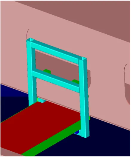
The lower platform has the same stops bolted to it as the upper platform, but does not have the clamps. The lower platform is held in place by a ladder structure that is detailed in Appendix A. The ladder is hung from the lightening holes of the test frame at any of a number of positions as needed. The hooks are welded to the ladder and simply and hung with the hooks inside the lightening holes. Figure 3 shows how the hooks, ladder, and test frame interact.
3.0 – Components
The required components for the platforms:
2 DE-STA-CO Model 213-U quick release clamps 8 fabricated aluminium stops as detailed in Appendix A
2 fabricated aluminium ladders with hooks as detailed in Appendix A 2 10 foot scaffolding platforms
32 8-32 socket head cap screws 8 8-32 hex nuts
4.0 – Conclusion
This document has presented the objective, criteria, and design of the platform for the ice tank carriage platform. A component list is included, as well as drawings detailing the necessary fabricated components. Section 5.0 shows several figures to demonstrate the layout of the design.
5.0 – Figures
Figure 1: Test Frame with Platform and Lower Platform
Figure 3: Ladder and Lower Platform