Département de génie civil
STRUCTURAL BEHAVIOR OF GFRP-RC
BRIDGE-DECK SLABS CONNECTED WITH UHPFRC
CLOSURE JOINTS IN ACCELERATED BRIDGE
CONSTRUCTION
ESSAIS STRUCTURAUX SUR DES DALLES DE PONTS
PRÉFABRIQUÉES EN BÉTON ARMÉ D’ARMATURE EN
PRFV JOINTÉES AVEC DU BÉTON AUX FIBRES À HAUTE
PERFORMANCE UTILISÉES EN CONSTRUCTION
ACCÉLÉRÉE DE PONTS
Thèse de doctorat
Spécialité : génie civil
Mohamed Hassan YOUSSEF
Sherbrooke (Québec) Canada
Mars 2019
MEMBRES DU JURY
Professeur Brahim BENMOKRANE Directeur de thèse
Professeur Sébastien LANGLOIS Rapporteur et examinateur Professeur Adel EL-SAFTY
Examinateur
Hany TOBBI, ing., Ph.D. Examinateur
ABSTRACT
Accelerated bridge construction (ABC) techniques have become increasingly commonplace alternatives to conventional construction techniques over the recent years. This thesis investigates the structural behavior of one common technique of ABC, using ultra-high-performance fiber-reinforced concrete (UHPFRC) closure joints between precast deck slabs. Glass fiber-reinforced polymer (GFRP) bars are used as alternative reinforcement in bridge-deck slabs to avoid steel corrosion problems, especially in harsh weather conditions. The experimental program consisted of two phases. Phase I included investigation of the UHPFRC closure joint located at the zone of maximum negative moment and subjected to flexural and shear stresses. In Phase II, however, the closure joints were positioned at the constant positive moment region and subjected to pure flexural stresses. A total of 14 full-scale slab specimens measuring 3,000 mm long × 1,000 mm wide × 225 mm thick were fabricated and tested to failure; Two specimens were cast monolithically without closure joints to serve as reference specimens, and 12 jointed specimens. The jointed specimen consisted of two GFRP-RC precast slabs connected with UHPFRC closure joint. Three splice lengths were developed, namely: 100, 150, and 200 mm, with a corresponding joint width of 120, 170, and 220 mm, respectively. Two reinforcement ratios were investigated using No. 15 and No. 20 GFRP bars with the same spacing. The test specimens were tested under monotonic line loading in two different schemes; cantilever-panel setup for Phase I and four-point bending for Phase II. The test results were discussed and analyzed in terms of crack pattern, load–deflection response, crack width, and GFRP-reinforcement and concrete strains. The load-carrying capacities of the specimens were predicted using the available bridge-codes and compared to the experimental capacities.
The findings of the current study demonstrated the feasibility of producing a short GFRP splice length embedded in UHPFRC closure joint to maintain the continuity between the precast slabs. The UHPFRC closure joints yielded adequate strength and performance until failure and remained intact without visible cracks.
Keywords: Accelerated bridge construction (ABC); ultra-high-performance
fiber-reinforced concrete (UHPFRC); precast concrete slabs; bridge deck; glass-fiber-fiber-reinforced- glass-fiber-reinforced-polymer (GFRP); joint; longitudinal joint; transverse joint; connection; deflection, shear strength, bridge design code; splice length; joint width.
RÉSUMÉ
Les techniques de construction accélérée de ponts (Accelerated bridge construction - ABC) sont devenues des solutions alternatives de plus en plus courantes aux techniques de construction conventionnelles au cours des dernières années. Cette thèse étudie le comportement structural d'une technique courante d'ABC, utilisant des joints de clavage en béton fibré à ultra-hautes performances (BFUP) entre des dalles de tablier préfabriquées. Les barres en polymère renforcé de fibres de verre (PRFV) ont été utilisées comme renforcement alternatif dans les dalles de tablier de pont afin d'éviter les problèmes de corrosion de l'acier, en particulier dans des environnements difficiles. Le programme expérimental comportait deux phases. La phase I comprenait le développement et l'étude de joints de clavage en BFUP situés dans la zone de moment négatif maximal et soumis à des contraintes de flexion et de cisaillement. Dans la phase II, les joints de clavage étaient positionnés dans la région du moment positif constant et soumis à des contraintes de flexion simple. Un total de 14 dalles pleine grandeur mesurant 3 000 mm de long, 1 000 mm de large et 225 mm d'épaisseur ont été fabriquées et testées jusqu'à la rupture. Deux spécimens ont été fabriqués sans joint de clavage pour servir de référence, tandis que 12 spécimens comportaient des joints de clavage. Le spécimen avec joint était composé de deux dalles préfabriquées avec des armatures de PRFV reliées à l’aide d’un joint de clavage en BFUP. Trois longueurs de recouvrement ont été considérées, à savoir : 100 mm, 150 mm et 200 mm, avec une largeur de joint correspondante de 120 mm, 170 mm et 220 mm, respectivement. Deux taux d’armature ont été étudiés en utilisant des barres n° 15 et n° 20 en PRFV avec le même espacement. Les dalles ont été testées sous charge linéaire monotone selon deux montages différents : un montage en porte-à-faux pour la phase I et un autre montage pour un essai de flexion quatre points pour la phase II. Les résultats des essais sont discutés et analysés en termes de patron de fissuration, de courbes charge-flèche, de largeur de fissures, et de déformations dans le béton et dans les armatures de
PRFV. Les capacités portantes des spécimens ont été prédites à l'aide des codes de pont existants et ont été comparées aux capacités portantes obtenues expérimentalement.
Les résultats de la présente étude ont démontré la possibilité de produire de courtes longueurs de recouvrement pour les barres de PRFV intégrées dans un joint clavage en BFUP afin d’assurer la continuité entre les dalles préfabriquées. Les joints clavage en BFUP ont démontré une résistance et une performance adéquates jusqu’à la rupture et sont restés intacts sans fissures apparentes.
Mots clés: Construction accélérée de ponts (ABC), béton fibré à ultra-hautes performances
(BFUP), dalles de béton préfabriquées, tablier de pont, polymère renforcé de fibres de verre (PRFV), joint, joint longitudinal, joint transversal, connexion, flèche, résistance au cisaillement, code de conception de pont, longueur de recouvrement, largeur de joint.
ACKNOWLEDGMENT
I would like to sincerely thank my supervisor, Dr. Brahim BENMOKRANE for initially believing in me and giving me the opportunity to perform this Ph.D. His constant availability and guidance have been invaluable. His dedication has certainly been an inspiration and I have learnt a lot from him throughout the Ph.D.
I am also very grateful to Dr. Ehab AHMED for his constant support, continuous encouragement, consulting, and guidance throughout the Ph.D.
I wish to acknowledge the financial support to this research from the Natural Sciences and Engineering Research Council of Canada (NSERC). I would like to thank the following companies for supplying materials for this research: Pultrall Inc. for providing the GFRP reinforcement and Lafarge-Holcim Canada Inc. for providing the Ductal® materials. I would also like to thank all my colleagues and friends at the University of Sherbrooke for their support friendliness streamlined during the period of Ph.D. I wish to express my gratitude to the technical staff of the new Canadian Foundation for Innovation (CFI) structural lab in the Department of Civil Engineering at the University of Sherbrooke for their help during the experimental work.
Last but certainly not least, I would like to say a special thank you to all my family members, who were patient and helped me to complete this research work.
TABLE OF CONTENTS
ABSTRACT ... I RÉSUMÉ ... III ACKNOWLEDGMENT ... V TABLE OF CONTENTS ... VII LIST OF TABLES ... XIII LIST OF FIGURES ... XV CHAPTER 1 INTRODUCTION ... 1
GENERAL BACKGROUND ... 1
1.1.
MOTIVATION OF THE RESEARCH ... 3 1.2.
OBJECTIVES AND SCOPE ... 4 1.3.
METHODOLOGY ... 5 1.4.
OUTLINE OF THE DISSERTATION ... 5 1.5.
CHAPTER 2 LITERATURE REVIEW ... 7
GENERAL ... 7
2.1.
ACCELERATED BRIDGE CONSTRUCTION (ABC) ... 8
2.2.
Why Consider ABC? ... 9 2.2.1.
Prefabricated Bridge Elements (Culmo, 2011) ... 10 2.2.2.
Prefabricated Deck Elements ... 10 2.2.2.1.
Prefabricated Beam Elements ... 11 2.2.2.2.
Examples of ABC Using UHPFRC Closure Joints ... 13 2.2.3.
Bridge Projects in Ontario ... 13 2.2.3.1.
Bridge Projects in New York ... 17 2.2.3.2.
FIBER REINFORCED POLYMER (FRP) BACKGROUND ... 20 2.3.
General... 20 2.3.1.
FRP Constituents and Manufacturing process ... 20 2.3.2. Fibers ... 22 2.3.3. Aramid fibers ... 22 2.3.3.1. Carbon fibers ... 22 2.3.3.2. Glass fibres ... 23 2.3.3.3. Resins... 24 2.3.4. FRP Reinforcing Products ... 25 2.3.5.
MECHANICALPROPERTIESOFUHPFRC ... 28 2.4.
General... 28 2.4.1.
Typical Composition of UHPC ... 28 2.4.2. Compressive Strength ... 29 2.4.3. Tensile Strength ... 30 2.4.4. Modulus of Elasticity ... 32 2.4.5. Flexural Strength ... 32 2.4.6. Poisson’s Ratio ... 33 2.4.7. Bond Strength ... 33 2.4.8. Shrinkage ... 33 2.4.9.
DESIGN OF GFRP-RCBRIDGE-DECK SLABS ... 34
2.5.
Design Approaches in the CHBDC (CAN/CSA S6, 2014) ... 34 2.5.1.
Flexural Design Method ... 34 2.5.1.1.
The Empirical Design Method ... 36 2.5.1.2.
Design Approaches in the AASHTO-LRFD ... 38 2.5.2. Empirical Design ... 39 2.5.2.1. Traditional Design... 41 2.5.2.2. Approximate Method ... 41 2.5.2.3.
CLOSURE JOINTS BETWEEN PREFABRICATED ELEMENTS ... 42
2.6.
SUMMARY ... 65
2.7.
CHAPTER 3 EXPERIMENTAL PROGRAM ... 67
INTRODUCTION ... 67
3.1.
EXPERIMENTAL RESEARCH PROGRAM ... 67 3.2. General ... 67 3.2.1. Material Properties ... 68 3.2.2. GFRP Reinforcement ... 68 3.2.2.1. Concrete ... 69 3.2.2.2.
Design, Parameters, and Specimens’ Details ... 70 3.2.3.
Specimen Design ... 70 3.2.3.1.
Details of Test Specimens ... 71 3.2.3.2.
Fabrication of Test Specimens ... 78 3.2.4.
Formwork... 78 3.2.4.1.
Reinforcing Cages ... 78 3.2.4.2.
Casting of NSC ... 81 3.2.4.3.
Casting of UHPFRC Closure Joints ... 81 3.2.4.4. Instrumentation ... 86 3.2.5. Phase I Specimens ... 86 3.2.5.1. Phase II Specimens... 87 3.2.5.2.
The Test Setup and Procedure ... 92 3.2.6.
Phase I Test Setup ... 92 3.2.6.1.
Phase II Test Setup ... 93 3.2.6.2.
CHAPTER 4 STRUCTURAL BEHAVIOR OF GFRP-RC BRIDGE-DECK SLABS CONNECTED WITH UHPFRC JOINTS UNDER FLEXURE AND SHEAR ... 97
ABSTRACT ... 98 4.1. INTRODUCTION ... 99 4.2. LITERATURE REVIEW ... 101 4.3. EXPERIMENTAL PROGRAM ... 103 4.4. Material Properties ... 103 4.4.1.
Details of Test Specimens... 104 4.4.2.
Fabrication of Test Specimens ... 108 4.4.3.
Test Setup and Procedure ... 109 4.4.4.
Instrumentation ... 111 4.4.5.
EXPERIMENTAL RESULTS AND DISCUSSION ... 111 4.5.
Crack Pattern and Mode of Failure ... 111 4.5.1.
Load–Deflection Behavior... 115 4.5.2.
Crack Width ... 117 4.5.3.
Strains in Reinforcement and Concrete ... 121 4.5.4.
COMPARISON BETWEEN PREDICTED AND EXPERIMENTAL SHEAR STRENGTH ... 123 4.6.
CONCLUSIONS ... 126 4.7.
CHAPTER 5 BEHAVIOR OF FIELD-CAST FULL-DEPTH UHPFRC MOMENT CLOSURE JOINTS BETWEEN PRECAST BRIDGE-DECK SLABS REINFORCED WITH GFRP BARS ... 129
ABSTRACT... 130 5.1. INTRODUCTION ... 131 5.2. PREVIOUS RESEARCH ... 133 5.3. EXPERIMENTAL PROGRAM ... 135 5.4. Material Characteristics ... 135 5.4.1.
Details and Fabrication of Test Specimens ... 136 5.4.2.
Instrumentation of Specimens ... 140 5.4.3.
Test Setup and Procedure ... 143 5.4.4.
TEST RESULTS AND OBSERVATIONS ... 143 5.5.
Crack Pattern and Failure Modes ... 144 5.5.1.
Effect of Test Parameters on Load-Deflection Response ... 149 5.5.2.
Crack Width ... 152 5.5.3.
Strains in GFRP-reinforcement and concrete ... 154 5.5.4.
Curvature and Deformability ... 157 5.5.5.
COMPARISON OF PREDICTED AND EXPERIMENTAL CAPACITIES ... 159
5.6.
CONCLUSIONS ... 161
5.7.
CHAPTER 6 GENERAL CONCLUSIONS AND RECOMMENDATIONS ... 165
SUMMARY ... 165
6.1.
CONCLUSIONS ... 166 6.2.
Closure Joints Subjected to Combined Shear and Flexural Stresses... 166 6.2.1.
Closure Joints Subjected to Pure Flexural Stresses ... 168 6.2.2.
RECOMMENDATIONS FOR FUTURE WORK ... 169
6.3.
CONCLUSIONS ... 170
6.4.
Joints de Clavage Soumis à une Combinaison de Contraintes de Cisaillement et de Flexion 6.4.1.
170
Joints de Clavage Soumis à des Efforts de Flexion Simple ... 172 6.4.2.
RECOMMANDATIONS POUR DES TRAVAUX FUTURS ... 173 6.5.
LIST OF TABLES
Table 2.1 - Approximate Properties of Common Grades of Glass Fibers (Bank 2007). ... 24
Table 2.2 - Typical Properties of Thermosetting Resins (ISIS Canada, 2007) ... 25
Table 2.3 - Typical mechanical Properties of FRP bars (ISIS Canada, 2007) ... 26
Table 2.4 - Typical mechanical properties of V-Rod GFRP bars (Pultrall, 2016) ... 27
Table 2.5 - Typical composition of Ductal® (Graybeal, 2006) ... 30
Table 3.1 - Mechanical properties of GFRP bars……….69
Table 3.2 – Test matrix and specimens details ... 73
Table 4.1 - Mechanical Properties of GFRP Bars………..103
Table 4.2 - Concrete and Reinforcement Details of the Test Specimens ... 107
Table 4.3 - Summary of the Experimental Results ... 113
Table 4.4 - Comparison of Measured Crack Widths at Service and Failure Loads ... 118
Table 4.5 - Ultimate Shear-Strength Prediction ... 124
Table 5.1 - Mechanical Properties of GFRP Bars………..136
Table 5.2 - Details of the Test Specimens ... 140
Table 5.3 - Summary of Test results ... 145
Table 5.5 - Curvature and Deformability of the Test Specimens ... 159 Table 5.6 - Prediction of Ultimate Shear Capacity ... 160
LIST OF FIGURES
Figure 1.1 -Typical orientation of the closure joints and their corresponding test specimens
... 2
Figure 2.1 - Typical bridge construction………9
Figure 2.2 - Examples of prefabricated deck elements (Culmo, 2011) ... 11
Figure 2. 3 - Examples of prefabricated deck beam elements (Culmo, 2011) ... 12
Figure 2.4 - Examples of prefabricated full-width beam elements (Culmo, 2011) ... 13
Figure 2.5 - The Rainy Lake Bridge on Highway 11 between Fort Frances and Atikokan, Ontario (photos by MTO) ... 14
Figure 2.6 – The Sunshine Creek Bridge on Highway 11/17 near Thunder Bay, Ontario (photo by MTO) ... 15
Figure 2.7 – The Hawk Lake Bridge on Highway 17 near Hawk Lake, Ontario (photos by MTO) ... 15
Figure 2.8 – The Chukuni River Bridge on Highway 105 over the Chukuni River near Red Lake, Ontario (photos by MTO) ... 16
Figure 2.9 - The Nipigon River Bridge on Highway 11/17 east of Thunder Bay, Ontario (photos by Ehab, A. Ahmed) ... 17
Figure 2.10 - Route 31 Bridge in Lyons, New York (photos by NYSDOT) ... 18
Figure 2.12 - Stress-strain relationships for fibrous reinforcement and matrix (ISIS Canada,
2007) ... 21
Figure 2.13- Basic material components of FRP ... 21
Figure 2.14 - Pultrusion process ... 21
Figure 2.15 - Typical stress strain relationships for FRPs compared to steel (ISIS Canada, 2007) ... 26
Figure 2.16 - Different shapes of FRP products (fib, 2007)... 27
Figure 2.17 - Tensile stress-strain response of UHPC (Graybeal et al. 2012) ... 31
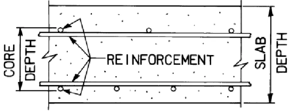
Figure 2.18 - Reinforcement in cast-in-place deck slab, Empirical design method, Clause 8.18.4.2, CAN/CSA S6 (2014) ... 37
Figure 2.19 - Reinforcement for cast-in-place deck slabs designed using the empirical method, (Clause 8.18.4.2, CAN/CSA S6, 2014) ... 38
Figure 2.20 - Core of a concrete deck slab Empirical design method, Article 9.7.2.4, AASHTO (2012) ... 40
Figure 2.21 - Specimen details and test setup (Zhu et al. 2011a)... 43
Figure 2.22 - Tension test setup (Zhu et al. 2011b) ... 44
Figure 2.23 - Four-point bending test (Hwang and Park, 2014) ... 46
Figure 2.24 - The test setup (Li et al. 2009a) ... 48
Figure 2.25 - The specimens’ dimensions and test setup (Li et al., 2009-b) ... 50
Figure 2.26 - The flexural test setup and specimen dimensions (Ma et al. 2012) ... 51
Figure 2.28 - Geometry and test setup of the test specimens (Lee and Lee, 2015) ... 54
Figure 2.29 - Test setup for transverse connection specimens (Graybeal, 2010) ... 55
Figure 2.30 - Test setup for longitudinal connection specimens (Graybeal, 2010) ... 56
Figure 2.31 - The test setup (Gar et al. 2014) ... 58
Figure 2. 32 - The test setup (Au and Lam, 2011) ... 59
Figure 2.33 - Layout of the bridge loading (Honarvar et al. 2015) ... 60
Figure 2.34 - Specimen dimensions and the test setup (Sayed-Ahmed and Sennah, 2015) 62 Figure 2.35 - The test setup and joint details (Harryson, 2003) ... 63
Figure 2.36 - Overall view of full-depth precast, post-tensioned concrete bridge deck system (Issa et al. 2007) ... 64
Figure 2.37 – Instrumentation and test setup (Haber and Graybeal, 2018) ... 65
Figure 3.1 - GFRP bars………68
Figure 3.2 - Identification of test specimens ... 71
Figure 3.3 – Concrete dimensions and reinforcement details of reference specimen (G-R-15-A) ... 74
Figure 3.4 – Concrete dimensions and reinforcement details of specimens G-100-15-A and G-100-20-A ... 74
Figure 3.5 – Concrete dimensions and reinforcement details of specimens G-150-15-A and G-150-20-A ... 75
Figure 3.6 – Concrete dimensions and reinforcement details of specimens G-200-15-A and G-200-20-A ... 75
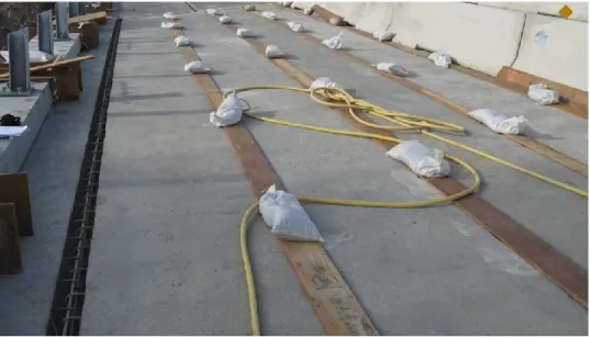
Figure 3. 7 – Concrete dimensions and reinforcement details of reference specimen (G-R-15-B) ... 76 Figure 3.8 – Concrete dimensions and reinforcement details of specimens G-100-15-B and G-100-20-B ... 76 Figure 3.9 – Concrete dimensions and reinforcement details of specimens G-150-15-B and G-150-20-B ... 77 Figure 3.10 – Concrete dimensions and reinforcement details of specimens G-200-15-B and G-200-20-B ... 77 Figure 3.11 - Overview of the formworks ... 79 Figure 3.12 – Istallation of strain gauges ... 79 Figure 3.13 – Assembled GFRP cages ... 79 Figure 3. 14 - Typical views of GFRP cages inside the formwork before concrete casting 80 Figure 3.15 - Casting of NSC slabs ... 82 Figure 3.16 - Typical view of slabs after casting and surfacing ... 82 Figure 3.17 - Curing of NSC slabs ... 82 Figure 3.18 – De-molding of NSC slabs ... 83 Figure 3.19 - Storing of NSC precast slabs ... 83 Figure 3.20 – UHPFRC Portable mixers ... 84 Figure 3.21 – Flow-table test ... 84 Figure 3.22 – Formwork for casting the closure joints ... 85 Figure 3.23 – Filling the joints with UHPFRC ... 85
Figure 3.24 – Curing of UHPFRC closure joints ... 85 Figure 3.25 – Full specimens ready for testing ... 86 Figure 3.26 - Locations of reinforcement and concrete strain gauges for reference specimen G-R-15-A ... 88 Figure 3.27 - Locations of reinforcement strain gauges for Phase I specimens ... 88 Figure 3.28 - Deflection measurements ... 89 Figure 3.29 – LVDTs to record the crack widths ... 89 Figure 3.30 - Locations of reinforcement and concrete strain gauges for reference specimen G-R-15-B ... 90 Figure 3.31 - Locations of reinforcement strain gauges for Phase II jointed specimens ... 90 Figure 3.32 - Potentiometer for the deflection at mid-span ... 91 Figure 3.33 - LVDTs for crack-width measurements ... 91 Figure 3.34 – Overview of the test setup for Phase I specimens ... 93 Figure 3.35 – Schematic view of the test setup for Phase I specimens ... 94 Figure 3.36 – The hinge and roller supports ... 94 Figure 3.37 – Overview of the test setup for Phase II specimens ... 95 Figure 3.38 – Schematic view of the test setup for Phase II specimens ... 95 Figure 4.1 - Typical concrete dimensions and reinforcement details ... 106 Figure 4.2 - Details of the joints and splices ... 107 Figure 4.3 - Fabrication of the reference specimen and precast slabs ... 108
Figure 4.4 - Construction of UHPFRC joint for the jointed specimens ... 109 Figure 4.5 - The test setup ... 110 Figure 4.6 - Typical instrumentation ... 112 Figure 4.7 - Typical crack pattern and mode of failure ... 114 Figure 4.8 - Load–deflection relationships... 116 Figure 4.9 - Load–flexural-crack-width relationships ... 119 Figure 4.10 - Load–interfacial-crack-width relationships ... 121 Figure 4.11 - Load–strain relationships ... 123 Figure 4.12 - Comparison between Vexp /Vpred values for the test specimens ... 125 Figure 5.1 - Load transfer mechanism through the UHPFRC closure joint………...132 Figure 5.2 - HM-GFRP reinforcing bars ... 135 Figure 5.3 - Geometry and reinforcement details of tested specimens ... 138 Figure 5.4 - The joint details ... 139 Figure 5.5 - Fabrication of the test specimens... 141 Figure 5.6 - Instrumentation of test specimens ... 142 Figure 5.7 - Testing setup ... 144 Figure 5.8 - Failure modes of the test specimens ... 146 Figure 5.9 - Bottom view of the typical crack pattern ... 147 Figure 5.10 - Typical bar slippage from the UHPFRC closure joint ... 149 Figure 5.11 - Typical load-deflection relationships ... 150
Figure 5.12 - Load-crack width relationships ... 153 Figure 5.13 - Load- GFRP strain relationships ... 156 Figure 5.14 - Load-curvature relationships for the jointed specimens ... 158 Figure 5.15 - Comparison of Vexp /Vpred for the test specimens ... 161
CHAPTER 1 INTRODUCTION
General Background
1.1.
Accelerated Bridge Construction (ABC) is a technique that uses innovative planning, design, materials, and construction methods in a safe and cost-effective manner to reduce the onsite construction time that occurs when building new bridges or replacing and rehabilitating existing bridges (Culmo, 2011). The use of prefabricated elements such as full-depth precast concrete deck panels has become more commonplace for over twenty years. The prefabricated full-depth bridge deck panels are connected by field-cast closure joints. The closure joints are cast using ultra-high-performance fiber-reinforced concrete (UHPFRC). The high early concrete strength and high bond strength of UHPFRC allow transferring the forces between the prefabricated deck panels through short splice lengths. This type of construction eliminates the need for cast in place formwork and reduces cost, construction time, and environmental impact. In addition, precast panels are constructed in a controlled environment which leads to a more durable and high quality product.
Ultra-high-performance fiber-reinforced concrete (UHPFRC) is a relatively new structural material composed of Portland cement, fine sand, silica fume, ground quartz, steel fibers, water and high range of water reducer (Graybeal, 2006a). UHPFRC has approximately four to eight times higher compressive strength and eight times higher abrasion resistance than Normal Strength Concrete (NSC). UHPFRC has compressive strength over 150 MPa, and its tensile strength ranges from 6.2 – 11.7 MPa (Graybeal, 2007).
The use of glass fiber-reinforced polymer reinforcement (GFRP) as alternative reinforcement has become of interest to overcome the problems of steel corrosion and associated deteriorations (Ahmed and Benmokrane, 2014). In deicing salts and aggressive environments, corrosion of steel reinforcement is a major factor affecting the structural
durability of precast panels and overall serviceability of a bridge deck. To prevent such corrosion problems, fiber-reinforced polymer (FRP) reinforcement has been proposed as a substitute for conventional steel reinforcement due to its high corrosion resistance and high strength to weight ratio.
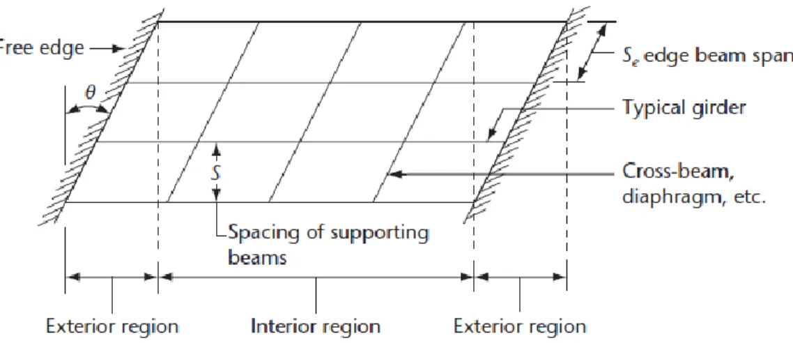
The closure joints in concrete bridge-decks may be subjected to either pure flexural stresses or combined flexural and shear stresses, depending on the type and location of the joints. The two common cases for the closure joints are longitudinal and transverse joints. Figure 1.1 shows a typical orientation of the closure joints indicating the corresponding test specimens. To determine the controlling load case of the longitudinal joint, the longitudinal joint should be located at the mid-span between longitudinal girders carrying the largest positive or negative moments. The transverse joint should be positioned over an interior support in a continuous span bridge system resisting moment and shear forces (French et al. 2011).
Figure 1.1 -Typical orientation of the closure joints and their corresponding test specimens
This research project aims at investigating the structural behavior of innovative UHPFRC closure joints between precast GFRP-RC bridge deck panels. The experimental program included the two common cases of closure joints. The specimens were designed to satisfy
requirements of the Canadian Highway Bridge Design Code CHBDC (CAN/CSA S6, 2014). The outputs of this research will contribute to extend the use of precast GFRP-RC bridge-deck panels with UHPFRC closure joints, which is an innovative solution to overcome the corrosion problems, eliminate the delay in construction, and improve the product durability. The findings of this study are expected to support the work of the North American technical committees engaged in developing standards and design provisions for GFRP-RC bridge-deck slabs connected with UHPFRC closure joints.
Motivation of the Research
1.2.
The use of GFRP reinforcement, which is corrosion resistant, eliminates the corrosion and related deterioration. Thus, it extends the service life of the RC structures especially in harsh exposure conditions.
The aging highway bridge infrastructure in North America is subjected to increasing traffic volumes and must be continuously renewed while accommodating traffic flow. Speed of construction, especially for the case of bridge replacement and repair projects, is an important factor. The use of prefabricated bridge systems can minimize traffic disruption, improve work-zone safety, minimize impact to the environment, improve constructability, increase quality, and lower the life-cycle costs. This technology is applicable and needed for both existing bridge replacement and new bridge construction (French et al. 2011). The need for more experimental data for the behavior of UHPFRC closure joints between prefabricated GFRP-RC deck panels under shear and flexural stresses is the primarily motivation for this study. In particular, considerable research in recent years has been undertaken to investigate the structural behavior of closure joints between prefabricated elements. However, there is still a need for solid recommendations for UHPFRC closure joints when GFRP is used as the primary reinforcement in concrete bridge-deck slabs The design specifications for RC highway bridges, such as the Canadian Highway Bridge Design Code CHBDC (CAN/CSA S6, 2014) and AASHTO LRFD (2009), do not provide guidelines or empirical equations for designing the UHPFRC closure joints for precast
deck systems. Therefore, this research project aims at providing design recommendations for such cases.
Objectives and Scope
1.3.
The main objective of this research project is to investigate and gain a better understanding of the structural behavior of UHPFRC closure joint connecting GFRP-RC bridge-deck panels under quasi-static loading. The specific objectives of the current study can be summarized as follows:
Evaluate the structural performance of the GFRP-RC precast bridge deck panels jointed by UHPFRC closure joints.
Compare the structural performance of the GFRP precast panels jointed by UHPFRC closure joints against the reference panels without a closure joint. Investigate the flexural behavior and serviceability performance of the
GFRP-RC jointed slabs under quasi-static loads.
Investigate the effect of different parameters on the structural behavior and serviceability performance of the jointed panels, such as the splice length (joint width) and longitudinal reinforcement ratio.
Prediction of the specimens’ load carrying capacities using the available bridge code provisions and compare these predicted capacities against experimental values.
Provide new design recommendations for UHPFRC closure joints between GFRP-RC deck slabs considering the joints in shear and flexural zones in the bridge system. These recommendations may contribute to update the current design standards such as the CHBDC (CAN/CSA S6, 2014).
Methodology
1.4.
To achieve the objectives of this research project, the experimental program includes construction and testing of 14 specimens representing full-depth UHPFRC closure joints between precast deck slabs. All the specimens measured 3,000 mm long × 1,000 mm wide × 225 mm thick and were reinforced with GFRP bars. Two specimens were cast monolithically without closure joint to serve as reference specimens. 12 jointed specimens, however, each contained two precast segments connected with UHPFRC closure joint simulating a common technique of accelerated bridge construction. Geometries and reinforcement details for all the test specimens are selected so satisfy the requirements of the Canadian Highway Bridge Design Code CHBDC (CAN/CSA S6, 2014). The test specimens were fabricated and tested under quasi-static loading up to failure. The test parameters were: splice length and joint width, GFRP reinforcement ratio, and the location of the closure joint. The experimental program is divided into two phases:
- Phase I includes 7 specimens: six jointed specimen and one reference specimen without closure joint. The closure joints were located at the zone of negative moment where subjected to combined flexural and shear stresses. The specimens were tested in a cantilever-panel setup with the closure joint located over the support.
- Phase II includes 7 specimens: six jointed specimens and one reference specimen without closure joint. The closure joints were located at the middle of the specimen within the zone of constant positive moment. The specimens were tested in a four-point bending scheme, at which the closure joints were subjected to pure flexural stresses.
Outline of the Dissertation
1.5.
This dissertation consists of six chapters; the following is a brief description of each chapter’s content:
Chapter 1 defines the problem, presents the main objectives, introduces the methodology, and provides an outline of the thesis with a brief description of each chapter.
Chapter 2 presents a review of literature on relevant work related to UHPFRC closure joints. The review includes the mechanical properties of GFRP bars and UHPFRC. The recently conducted studies concerning ABC are also reviewed. Chapter 3 describes the conducted experimental program. It presents the geometry
and reinforcement details of the test specimens including fabrication, instrumentation, and testing procedures.
Chapter 4 presents the first paper in this dissertation entitled ―Structural Behavior of GFRP-RC Bridge-Deck Slabs Connected with UHPFRC Joints under Flexure and Shear‖. This chapter provides an investigation of the behavior of GFRP-RC bridge-deck slabs jointed with full-depth UHPFRC closure joint. Seven full-scale one-way slab specimens were tested up to failure, considering the closure joint subjected to shear and flexural stresses. The influences of the test parameter on the structural behavior of the tested specimens were investigated.
Chapter 5 presents the second paper in this dissertation entitled ―Behavior of Field-Cast Full-Depth UHPFRC Moment Closure Joints between precast Bridge-Deck Slabs reinforced with GFRP bars‖. This chapter investigates the behavior of the UHPFRC closure joint between GFRP-RC bridge-deck slabs under pure flexural stresses. Seven full-scale one-way slab specimens were fabricated and loaded to collapse. The effects of the test parameter on the structural behavior and serviceability of the tested specimens were studied.
Chapter 6 presents the summary, conclusions based on the test results, and recommendation for future research work.
CHAPTER 2 LITERATURE REVIEW
General
2.1.
This chapter mainly reviews previous relevant studies into the use of ultra-high-performance fiber-reinforced concrete (UHPFRC) closure joints between GFRP-RC prefabricated elements in accelerated bridge construction (ABC). A brief investigation about the use of ABC as an alternative technique to conventional construction is reviewed. This chapter, however, includes the basic mechanical properties of fiber-reinforced polymer (FRP) reinforcement as an alternative to steel reinforcement in addition to the mechanical properties of UHPFRC. Design provisions of GFRP-RC deck slabs in bridge codes and guidelines are also presented in this chapter.
(Culmo, 2011) presented a manual giving all respects of accelerated bridge construction (ABC). The intent of this manual was to fill in the gaps left by publication of the previous manuals. The manual covered ABC techniques, project planning and scoping, implementing ABC in a Transportation Agency, and prefabricated elements.
Glass fiber-reinforced Polymer (GFRP) reinforcing bars provide a promising solution for corrosion due to their non-corrosive nature. GFRP bars are commonly available as grade I, II, and III (CAN/CSA S807, 2010). The Canadian Highway Bridge Design Code CHBDC (CAN/CSA S6, 2014) and AASHTO-LRFD Bridge Design Guide Specifications for GFRP-Reinforced Concrete Bridge-Decks and Traffic Railings (AASHTO, 2009) allow the use of GFRP as a primary reinforcement in reinforced concrete bridges.
Russell and Graybeal (2013) provided an extensive review on UHPFRC including information about materials and production, mechanical properties, structural design and structural testing, durability and durability testing, and actual and potential applications. In
the report, UHPFRC were defined as cementitious-based composite materials with discontinuous fiber reinforcement that exhibit compressive strength above 150 MPa, pre- and post-cracking tensile strength above 5 MPa, and enhanced durability via a discontinuous pore structure.
There has been a considerable amount of research and experience with full-depth closure joints between precast concrete elements, as well as precast deck panels installed on steel girders. Most of these researches studied the closure joints with steel reinforcement, while a few of them used GFRP reinforcing bars. Moreover, the closure joints reinforcement had different configurations. Review of the structural testing of such structural elements is presented in section 2.5.
Accelerated Bridge Construction (ABC)
2.2.
ABC is a bridge construction technique that uses innovative planning, design, materials, and construction methods in a safe and cost-effective manner to reduce the onsite construction time that occurs when building new bridges or replacing and rehabilitating existing bridges (Culmo, 2011). Over the last 20 years, there have been progressive advancements in the use of ABC, for instance, bridge deck construction using full depth precast concrete deck panels. More recently, ABC projects have spread to all bridge elements including substructures and foundations.
On the other hand, Conventional bridge construction does not significantly reduce the onsite construction time that is needed to build, replace, or rehabilitate of bridge projects. Conventional construction methods involve onsite activities that are time consuming and weather dependent. In conventional bridge construction, only the concrete or steel girders can be prefabricated. In contrast, all bridge components can be prefabricated in case of accelerated bridge construction. Figure 2.1 shows a comparison between the two bridge construction techniques.
Figure 2.1 - Typical bridge construction
Why Consider ABC?
2.2.1.
A common reason to choose ABC is to reduce traffic impacts because the safety of the traveling public and the flow of the transportation network are directly affected by onsite construction related activities. However, other common and equally viable reasons to use ABC deal with site constructability issues. In addition, long detours, costly use of temporary structures, remote site locations, and limited construction periods present opportunities where the use of ABC methods can provide more practical and economical solutions compared with the conventional construction methods (Culmo, 2011). The benefits of using UHPFRC in ABC projects can be summarized as follows:
Improve site constructability, total project delivery time, material quality, and long-term durability. The bridge elements are prefabricated under controlled environmental conditions and jointed in site by short width field-cast closure joints. Increase safety for the workers and traveling public.
Reduce traffic impacts and weather-related time delays by shortening the onsite construction time.
Minimize environmental impacts and impacts to existing roadway alignment. Increases the benefit cost ratio of the project by reducing the required maintenance
and extending the service life.
Prefabricated Bridge Elements (Culmo, 2011)
2.2.2.
The use of prefabricated bridge elements and systems is a technique that meets the objectives of accelerated bridge construction. Prefabricated elements reduce the onsite construction time and mobility impact time compared to conventional construction systems. Bridge elements are typically built in a prefabricated and repeatable manner to offset costs. The elements are built under controlled environmental conditions, avoiding the influence of weather related impacts, to achieve better product quality and long-term durability.
The use of innovative materials such as ultra-high-performance fiber-reinforced concrete (UHPFRC) in filling the joints between prefabricated elements can significantly help to achieve the objectives of ABC. This is because of the exceptional properties of UHPFRC, especially the high early compressive strength. ABC systems include the entire superstructure (decks and girders) and substructure (abutments and piers) prefabricated components, the following contains examples of the most common prefabricated superstructure elements in ABC systems.
Prefabricated Deck Elements 2.2.2.1.
Prefabricated deck system eliminates activities that are associated with conventional deck construction, which typically includes onsite installation of deck forms, overhang bracket and formwork installation, reinforcing bars placement, paving equipment set up, concrete placement, and concrete curing, all typically occurring in a sequential manner. Some examples of prefabricated deck element systems are listed below, Figure 2.2 shows some examples of prefabricated deck elements.
Partial-depth precast deck panels; Full-depth precast deck panels; Light-weight precast deck panels; and Orthotropic deck.
Figure 2.2 - Examples of prefabricated deck elements (Culmo, 2011)
Prefabricated Beam Elements 2.2.2.2.
Prefabricated beam elements are composed of two types: deck beam elements and full-width beam elements. Deck beam elements eliminate conventional onsite deck forming activities, see Figure 2.3. To reduce onsite deck forming operations, deck beam elements are typically placed in an abutting manner. Examples of Deck Beam Elements include:
Adjacent deck bulb tee beams, Adjacent double tee beams, Adjacent inverted tee beams, and Modular beams with decks.
(d) Orthotropic deck (c) Light-weight precast deck panels
Full-width beam elements, shown in Figure 2.4, eliminate conventional onsite beam placement activities. They are typically rolled, slid, or lifted into place to allow deck placement operations to begin immediately after placement. Examples of Full-Width Beam Elements include:
Truss span without deck, and Arch span without deck.
(c) Adjacent inverted tee beams (d) Modular beams with decks (b) Adjacent double tee beams (a) Adjacent deck bulb tee beams
Figure 2.4 - Examples of prefabricated full-width beam elements (Culmo, 2011)
Examples of ABC Using UHPFRC Closure Joints
2.2.3.
Recently, in North America, The use of field-cast UHPFRC closure joints between precast concrete modular components has become commonplace. UHPFRC allows for simplified joint details, rapid construction time, and more durable structure. field-cast UHPFRC closure joints between prefabricated bridge components have been implemented in many bridges in North America (Perry and Royce, 2010; Graybeal, 2011; Arafa et al. 2016). A general overview of some of these projects in Canada and the United States is provided below.
Bridge Projects in Ontario 2.2.3.1.
The Ministry of Transportation of Ontario (MTO) has been a leader in deployment of field-cast UHPFRC connection technology (Graybeal, 2010). MTO has completed construction of many bridges in Ontario, with UHPFRC closure joints between precast concrete elements, starting from 2006 up to date. The type of UHPFRC used in all Ontario bridge projects was Ductal® developed by Lafarge-Holcim (Lafarge, 2009). In 2006, the Rainy Lake Bridge was constructed on Highway 11 between Fort Frances and Atikokan, Ontario. This project used precast bridge deck panels to rehabilitate the deck on a single span steel stringer bridge. UHPFRC (Ductal®) was used in joints between adjacent deck panels as well as in the composite joint between the panels and the girders. The joints were
Arch span without deck Truss span without deck
200 mm in width and included straight GFRP reinforcing bars (Ductal, 2016). Figure 2.5 provides photos of the Rainy Lake Bridge showing the joints before and after casting.
Figure 2.5 - The Rainy Lake Bridge on Highway 11 between Fort Frances and Atikokan, Ontario (photos by MTO)
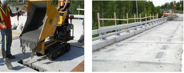
In 2007, the Sunshine Creek Bridge was constructed on Highway 11/17 near Thunder Bay, Ontario. This project included the removal of the existing simple span superstructure and the replacement with 10 adjacent box girders of 21 m length. 9 longitudinal joints along the length of the girders were cast with a field-cast Ductal® UHPFRC joints (Ductal, 2016). The joints had diamond-shaped shear keys including hairpin-shaped GFRP details (Figure 2.6).
The Hawk Lake Bridge, owned by MTO, was constructed on Highway 17 near Hawk Lake, Ontario in 2008. The project included 12 side-by-side precast box girders connected with 11 Ductal® UHPFRC closure joints (Ductal, 2016). The joints had a diamond-shaped shear keys between the simple span precast girders of length 27.2 m, and reinforced with GFRP straight bars, as shown in Figure 2.7.
Figure 2.6 – The Sunshine Creek Bridge on Highway 11/17 near Thunder Bay, Ontario (photo by MTO)
Figure 2.7 – The Hawk Lake Bridge on Highway 17 near Hawk Lake, Ontario (photos by MTO)
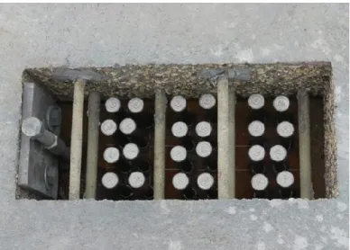
The longest single span bridge in Canada, the Chukuni River Bridge, was constructed on Highway 105 over the Chukuni River near Red Lake, Ontario in 2010. It has 101 m long with a clear span of 83.5 m (Ductal, 2016). This project included four 3.7 m deep steel girders and 54 half-width conventional concrete precast deck panels. The longitudinal and transverse joints were constructed with field-cast UHPFRC. The discrete reinforcement in
the joints included straight GFRP bars. The UHPFRC also completed the composite connections to the girders in the periodic shear pockets and provided the bedding under the deck panels, each 3.6 m wide panel contained two shear pockets. Figure 2.8 shows photos of the bridge construction.
Figure 2.8 – The Chukuni River Bridge on Highway 105 over the Chukuni River near Red Lake, Ontario (photos by MTO)
GFRP straight splices Shear pockets
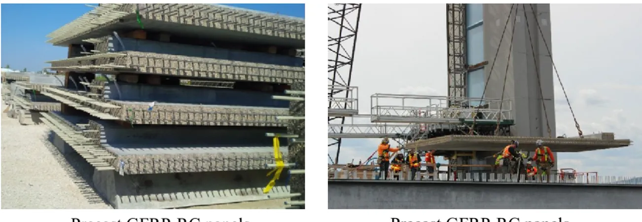
The world’s first cable-stayed bridge with GFRP-RC deck slabs, the Nipigon River Bridge, was completed over the Nipigon River as part of the extension of the Highway 11/17 east of Thunder Bay, Ontario in 2017. The bridge consisted of two traffic lanes and a pedestrian sidewalk in each direction, with a total width of 36.2 m and 251.8 m total length. It is divided into two spans supported on three central towers 51 m in height. The precast panels were 225 mm thick and reinforced with two No. 15 HM-GFRP bars extended inside 220-mm rectangular closure joints. Four hundred and eighty precast panels measuring 3×7 m were precast for the bridge deck (Arafa et al. 2016). Figure 2.9 shows the stacked GFRP-RC precast panels and their installation on the bridge deck.
Figure 2.9 - The Nipigon River Bridge on Highway 11/17 east of Thunder Bay, Ontario (photos by Ehab, A. Ahmed)
Bridge Projects in New York 2.2.3.2.
The New York State Department of Transportation (NYSDOT) has played a significant role in advancing the use of field-cast UHPFRC closure joints between modular bridge components. NYSDOT has a strong interest in using full-depth precast deck panels and deck-bulb-tee prestressed girders for use in constructing and reconstructing bridges. In both bridge types, the precast concrete elements are connected together at the deck level via permanent, durable joints. The long-term performance of the bridge is dependent on acceptable performance of the joints (Graybeal, 2010). In 2009, NYSDOT constructed two bridges using field-cast UHPFRC joints between prefabricated elements. The first bridge
was the Route 31 Bridge in Lyons, New York. In this bridge superstructure replacement, newly fabricated 1.04 m deep prestressed concrete deck-bulb-tee girders were installed in the bridge over the Canandaigua Outlet. The longitudinal joint width was 152 mm with a diamond shear key, 16M straight epoxy-coated steel bars projected from precast girder decks into the joint 150 mm splice length. Figure 2.10 provides photos showing the longitudinal joints and the completed bridge.
Figure 2.10 - Route 31 Bridge in Lyons, New York (photos by NYSDOT)
Longitudinal joints Casting of UHPFRC
The other project in 2009 was replacement of the Route 23 Bridge in Oneonta, New York. The bridge included the use of full-depth precast deck panels and field-cast UHPFRC transverse joints. The diamond-shaped joint reinforcement consisted of epoxy-coated hair pin 13M mild-steel reinforcement with a lap length of 100 mm. The UHPC was mixed, cast, and cured. After curing, a 40 mm thickness concrete overlay was installed so as to provide a smooth riding surface (Graybeal, 2010). Figure 2.11 shows construction of the Route 23 Bridge project.
Figure 2.11 - Route 23 Bridge in Oneonta, New York (photos by NYSDOT)
Transverse joints Field casting of UHPFRC
Fiber Reinforced Polymer (FRP) background
2.3.
General
2.3.1.
During the last decade, fiber reinforced polymer (FRP) materials have been extensively used as a practical alternative material for steel reinforcing bars in concrete structures. FRP reinforcing bars offer advantages over steel reinforcement in which FRP bars have an excellent corrosion resistance and high strength-to-weight ratio compared to steel. This part provides general information and properties of the FRP composite materials. It is focusing on composition, types, compressive and tensile properties, and the use of FRP as reinforcement for concrete structures.
FRP Constituents and Manufacturing process
2.3.2.
FRP products are composite materials which consist of a matrix (resin) and reinforcing fibers. As shown in Figure 2.12, the fibers are stronger than the matrix. In order to provide the reinforcing function, the fiber-volume fraction should be more than 55 percent for FRP bars and rods and 35 percent for FRP grids (ISIS Canada, 2007). The matrix not only coats fibers and protects them from mechanical abrasion, but also transfers stresses between them (Figure 2.13). Moreover, it transfers inter-laminar and in-plane shear in the composite, and provides lateral support to fibers against buckling when subjected to compressive loads. Additives and fillers may be added for curing or enhancing mechanical and/or physical properties.
Pultrusion is a common technique for manufacturing continuous lengths of FRP bars that are of constant or nearly constant profile. A schematic representation of this technique is shown in Figure 2.14. Continuous strands of reinforcing material are drawn from creels, through a resin tank, where they are saturated with resin, and then through a number of wiper rings into the mouth of a heated die. The speed of pulling through the die is predetermined by the curing time needed. To ensure good bond with concrete, the surface of the bars is usually braided or sand-coated. The most common products manufactured using this process are pipes, tubes, and storage tanks (ISIS Canada, 2007).
Figure 2.12 - Stress-strain relationships for fibrous reinforcement and matrix (ISIS Canada, 2007)
Figure 2.13- Basic material components of FRP
FRP bar Stress
Fibers Matrix
Fibers
2.3.3.
Fibers used for manufacturing composite materials must have high strength and stiffness, toughness, durability and preferably low cost. The performance of fibers is affected by their length, cross-sectional shape and chemical composition. Fibers are available in different cross-sectional shapes and sizes. The most commonly used fibers for FRPs are aramid, carbon, and glass (ISIS Canada, 2007).
Aramid fibers 2.3.3.1.
Aramid fibers were used to produce first-generation FRP pre-stressing tendons in the 1980 in Europe and Japan; however, few manufacturers still produce aramid fiber FRP reinforcing bars or tendons.
A combination of their relatively high price, difficulty in processing, high moisture absorption (up to 6% by weight), low melting temperatures (around 425oC), and relatively poor compressive properties have made them less attractive for FRP parts for structural engineering applications (Bank 2006). Their advantages include extremely high tenacity and toughness. Like carbon fibers, they have a negative coefficient of thermal expansion in the fiber longitudinal direction. They are the lightest of the high performance fibers, having a density of around 1.4 g/cm3. Depending on the type of aramid fiber, the fiber longitudinal
tensile strength ranges from 3400 to 4100 MPa, and its longitudinal tensile modulus ranges from 70 to 125 GPa.
Carbon fibers 2.3.3.2.
Carbon fibers are used in FRP strengthening sheets and fabrics, in FRP strengthening strips, and in FRP pre-stressing tendons. Carbon fiber is a solid semi crystalline organic material consisting on the atomic level of planar two-dimensional arrays of carbon atoms. The two-dimensional sheet is usually known as the graphitic form; hence, the fibers are also known as graphite fibers (the three-dimensional array is well known as the diamond form). Carbon fiber is produced in grades known as standard modulus (SM), intermediate modulus (IM), high strength (HS), and ultra-high modulus (UHM).
The longitudinal axis of the fiber is parallel to the graphitic planes and gives the fiber its high longitudinal modulus and strength. Carbon fiber is produced at high temperatures (1200 to 2400o C) from three possible precursor materials: a natural cellulosic rayon textile fiber, a synthetic polyacrilonitrile (PAN) textile fiber, or pitch (coal tar). The carbon fibers are very durable and perform very well in hot and moist environments and when subjected to fatigue loads (Bank 2006). They do not absorb moisture. They have a negative or very low coefficient of thermal expansion in their longitudinal direction, giving them excellent dimensional stability. They are, however, thermally and electrically conductive.
Glass fibres 2.3.3.3.
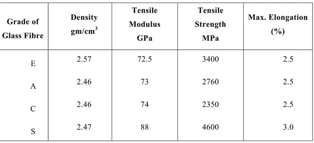
Glass fiber is a material made from extremely fine fibers of glass, and it is the largest reinforcement measured in sales. The glass fiber was invented in 1938 by Russell Games Slayter of Owens-Corning as a material to be used as insulation. Ever since then, glass fiber has become widely used as insulation and composite reinforcement material. Based on the composition and the application, glass fibers can be classified in several types. The most commonly used glass fiber type for composite applications are E-glass (electrical glass) and S-glass (structural or high-strength glass). The E-glass has good mechanical properties and high electrical insulation. S-glass is also used in composite materials where high tensile strength is desired; however this material comes at a much higher cost. The glass fibers are excellent thermal and electrical insulators and are the most inexpensive of the high-performance fibers (Bank 2007). Table 2.1 indicates approximate properties of common grades of glass fibers.
Table 2.1 - Approximate Properties of Common Grades of Glass Fibers (Bank 2007) Grade of Glass Fibre Density gm/cm3 Tensile Modulus GPa Tensile Strength MPa Max. Elongation (%) E 2.57 72.5 3400 2.5 A 2.46 73 2760 2.5 C 2.46 74 2350 2.5 S 2.47 88 4600 3.0
Resins
2.3.4.
Selection of the proper matrix is a very important issue in the manufacture of composites because the physical and thermal properties of the matrix significantly affect the final mechanical properties as well as the manufacturing process. In order to be able to exploit the full strength of the fibers, the matrix should be able to develop a higher ultimate strain than the fibers (Phillips, 1989). Very important roles of the matrix are transfer of inter-laminar and in-plane shear in the composite, and provision of lateral support to fibers against buckling when subjected to compressive loads. There are two types of polymeric matrices widely used for FRP composites; namely, thermosetting and thermoplastic. Thermosetting polymers are used more often than thermoplastic. They are low molecular-weight liquids with very low viscosity (ACI 1995), and their molecules are joined together by chemical cross-links. Hence, they form a rigid three dimensional structure that once set, cannot be reshaped by applying heat or pressure. Thermosetting polymers are processed in a liquid state to obtain good wet-out of fibers. Some commonly used thermosetting polymers are polyesters, vinyl esters and epoxies. These materials have good thermal stability and chemical resistance and undergo low creep and stress relaxation. The FRP reinforcing bars should be produced and properly cured with a degree of curing above 95
percent (ISIS Canada, 2007). However, these polymers have relatively low strain to failure, resulting in low impact strength. Two major disadvantages are their short shelf life and long manufacturing time. Mechanical properties of some thermoset resins are provided in Table 2.2.
FRP Reinforcing Products
2.3.5.
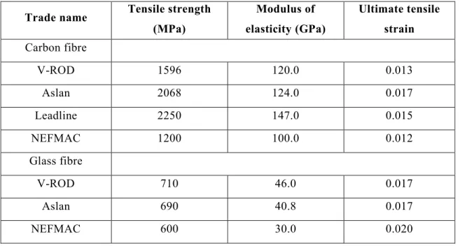
FRP reinforcing bars are manufactured from continuous fibers (such as aramid, carbon, and glass) embedded in matrices (thermosetting or thermoplastic). Similar to steel reinforcement, FRP bars are produced in different diameters, depending on the manufacturing process. The surface of the rods can be spiral, straight, sanded-straight, sanded-braided, and deformed. The bond of these bars to concrete is usually equal to, or better than, the bond of steel bars (ISIS Canada, 2007). Table 2.3 gives the mechanical properties of some commercially available FRP reinforcing bars. Figure 2.15 shows typical stress strain relationships for aramid, carbon, and glass FRP bars compared to steel and Figure 2.16 shows typical different shapes of FRP products. Table 2.4 presents typical mechanical properties of V-Rod GFRP bars developed by Pultrall Inc. (Pultrall, 2016).
Table 2.2 - Typical Properties of Thermosetting Resins (ISIS Canada, 2007) Resin Specific Gravity Tensile Strength (MPa) Tensile Modulus (GPa) Cure Shrinkage (%) Epoxy 1.20-1.30 55.00-130.00 2.75-4.10 1.00-5.00 Polyester 1.10-1.40 34.50-103.50 2.10-3.45 5.00-12.00 Vinyl Ester 1.12-1.32 73.00-81.00 3.00-3.35 5.40-10.30
Table 2.3 - Typical mechanical Properties of FRP bars (ISIS Canada, 2007)
Trade name Tensile strength
(MPa) Modulus of elasticity (GPa) (GPa) Ultimate tensile strain Carbon fibre V-ROD 1596 120.0 0.013 Aslan 2068 124.0 0.017 Leadline 2250 147.0 0.015 NEFMAC 1200 100.0 0.012 Glass fibre V-ROD 710 46.0 0.017 Aslan 690 40.8 0.017 NEFMAC 600 30.0 0.020
Figure 2.15 - Typical stress strain relationships for FRPs compared to steel (ISIS Canada, 2007)
Figure 2.16 - Different shapes of FRP products (fib, 2007)
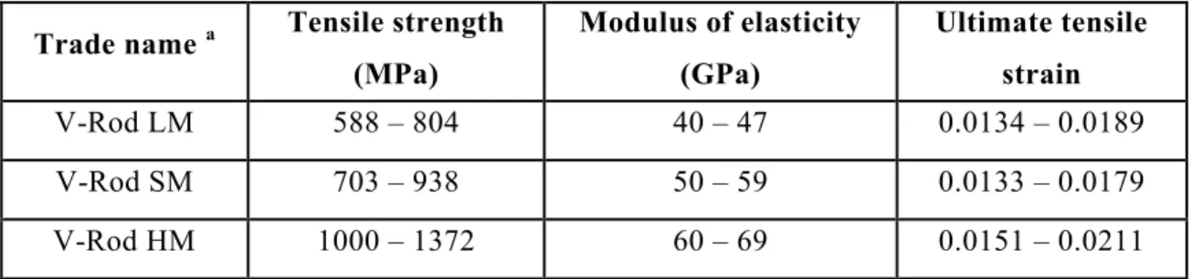
Table 2.4 - Typical mechanical properties of V-Rod GFRP bars (Pultrall, 2016)
Trade name a Tensile strength
(MPa) Modulus of elasticity (GPa) Ultimate tensile strain V-Rod LM 588 – 804 40 – 47 0.0134 – 0.0189 V-Rod SM 703 – 938 50 – 59 0.0133 – 0.0179 V-Rod HM 1000 – 1372 60 – 69 0.0151 – 0.0211
a LM: low modulus; SM: standard modulus; and HM: high modulus, according to the manufacturer.
MECHANICAL PROPERTIES OF UHPFRC
2.4.
General
2.4.1.
Ultra High Performance Concrete (UHPC) refers to a class of advanced cementitious composite materials. UHPC is a relatively new structural material composed of Portland cement, fine sand, silica fume, ground quartz, steel fibers, water and high range of water reducer (Graybeal 2006a).
Concrete or cementitious composites with compressive strength over 150 MPa are generally described as ultra-high-performance concrete (UHPC), if steel fibers are added in order to decrease brittleness and increase energy absorption capacity the term ultra-high-performance fiber-reinforced concrete (UHPFRC) is used (Yuguang et al. 2008). This part summarizes the current knowledge related to characterization of Ultra High Performance Concrete (UHPC). It is focusing on composition, types, compressive and tensile properties. UHPC is used in several bridge applications, including precast, prestressed girders, precast waffle panels for bridge decks, and as a jointing material between precast concrete deck panels and girders and between the flanges of adjacent girders. In Canada, the first UHPC bridge was constructed in 1997. This pedestrian bridge consists of a precast, post-tensioned space truss. At least 26 bridges have been built in Canada using UHPC in one or more components (Russell and Graybeal, 2013).
Typical Composition of UHPC
2.4.2.
UHPC formulations often consist of a combination of portland cement, fine sand, silica fume, high-range water-reducing admixture (HRWR), fibers (usually steel), and water. Small aggregates are sometimes used, as well as a variety of chemical admixtures. Different combinations of these materials may be used, depending on the application and supplier (Russell and Graybeal, 2013).
The UHPFRC used most often in North America for both research and applications is a commercial product known as Ductal® made by Lafarge Company. Table 2.5 shows a typical composition of this product (Graybeal, 2006a).
Compressive Strength
2.4.3.
Compressive strength is an important property in the design of any concrete structure. It is also the property that is most frequently measured. Several studies have been conducted to investigate the compressive strength of UHPC. Cylinder and cube compression test methods used for conventional concrete are appropriate for the determination of UHPC compressive strength.
Graybeal (2006a) reported the compressive strengths of nearly 1,000 specimens subjected to the following four different curing conditions:
a) Steam curing at (90°C) and 95-percent relative humidity for 48 hours starting about 24 hours after casting.
b) Steam curing at (60°C) for 48 hours starting about 24 hours after casting. c) Steam curing at (90°C) for 48 hours starting about 15 days after casting. d) Curing under laboratory conditions (23°C) and ambient humidity.
Density of the UHPC ranged from 2400 to 2500 kg/m3. The tests were conducted on (76 by 152 mm) cylinders, generally used the procedures of ASTM C39 (ASTM, 2005), except the loading rate was increased to (1 MPa/s), and a (165 mm) diameter spherical bearing plate was used.The average measured compressive strengths at 28 days for six cylinders cured using methods a, b, c, and d were (193, 171, 171, and 126 MPa), respectively.
Richard (1996) reported that compressive strengths as high as 550 MPa can be achieved at atmospheric pressure and heat treating at 250 °C. With pressure, compressive strengths as high as 810 MPa are possible. With conventional production capabilities and curing at 90 °C, strengths of 280 MPa can be achieved.
Table 2.5 - Typical composition of Ductal® (Graybeal, 2006a)
Material Amount (kg/m3) Percent by weight (%)
Portland cement 712 28.5 Fine sand 1020 40.8 Silica fume 231 9.3 Ground quartz 211 8.4 Super-plasticizer 30.7 1.2 Accelerator 30 1.2 Steel fiber 156 6.2 Water 109 4.4
Tensile Strength
2.4.4.
In conventional structural design for concrete structures, the tensile strength of concrete is assumed to be zero in reinforced concrete design. The tensile strength of UHPC is higher than that of conventional concrete, and UHPC can exhibit sustained tensile strength after first cracking. The results of tests for tensile strength of UHPC, therefore, often report a value of first cracking strength as well as a peak post-cracking strength. Consequently, tensile strength takes on increasing importance as a property to consider in design (Russell and Graybeal, 2013).
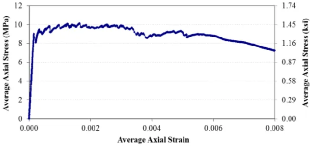
Graybeal et al. (2012) captured the tensile stress-strain response obtained from a readily available UHPC containing 2 percent by volume steel fiber reinforcement. The results are indicated in Figure 2.17.
Figure 2.17 - Tensile stress-strain response of UHPC (Graybeal et al. 2012)
Graybeal (2006a) reported measurements of tensile strength using flexural prisms, split cylinders, mortar briquettes, and direct tension tests of cylinders. The combined results of these tests indicated a first tensile cracking strength of approximately (9.0 MPa) for steam-cured specimens and approximately (6.2 MPa) without any heat treatment.
Graybeal and Baby (2013) conducted a uniaxial direct tension test on UHPC. This test method is based on a standard tension test applied to metals, provides the uniaxial tensile mechanical response of UHPC and is applicable to both cast and extracted test specimens. Tests were completed on two UHPCs containing multiple steel fiber reinforcement percentages and cured through ambient laboratory and steam-treated conditions. The results demonstrated that these two UHPCs could sustain more than 9 MPa of uniaxial tensile load. In the split cylinder tests (ASTM C496, 2011), measured splitting tensile strengths at first cracking were (11.7 MPa) for steam-cured specimens and (9.0 MPa) for untreated specimens. For the steam-cured specimens, the splitting tensile strengths at first cracking varied from 3 to 5 percent of the measured compressive strength. The post-cracking peak tensile splitting stresses ranged from 12 to 16 percent of the compressive strength.
According to JSCE (2006) recommendations, when a commercially available UHPC constituent material used, the average tensile strength is found to vary between 10 to 15 MPa. The direct tensile test would be essentially the best way to obtain the tensile strength and tension softening characteristics.
Modulus of Elasticity
2.4.5.
The modulus of elasticity of normal strength concrete with compressive strengthvalues of 28 to 55 MPa is typically 25 to 35 GPa (ACI, 2014). The elastic modulus of high performance concrete (HPC) with compressive strengths of 83 to 124 MPa is approximately 33 to 44 GPa (ACI, 1992). UHPC has a high elastic modulus typically in the range of 57 to 70 GPa (Richard and Cheyrezy, 1995).
Graybeal (2006a) measured the modulus of elasticity of six cylinders in compression in accordance with ASTM C469 (ASTM, 2002) at ages from 1 to 56 days. After steam curing, the measured values were about 50 GPa. Cylinders cured under standard laboratory conditions had modulus of elasticity values of about 42.7 GPa at 28 days.
The modulus of elasticity was also measured in direct tension tests. The average measured values were 51.9 GPa for steam treated specimens and 47.6 GPa for untreated specimens. These values were slightly higher than those measured in compression (Russell and Graybeal, 2013).
Flexural Strength
2.4.6.
UHPC has superior flexural strength compared to normal and HPC. The UHPC has a flexural strength around 30 - 60 MPa and had a toughness of 250 times that of normal strength concrete (Richard and Cheyrezy, 1995). Typical UHPC behavior under flexure is characterized by linear elastic behavior up to the first cracking strength of the material, a strain-hardening phase up to the maximum load, and a strain softening phase after the maximum load is reached.