HAL Id: tel-00908428
https://tel.archives-ouvertes.fr/tel-00908428
Submitted on 22 Nov 2013HAL is a multi-disciplinary open access archive for the deposit and dissemination of sci-entific research documents, whether they are pub-lished or not. The documents may come from teaching and research institutions in France or abroad, or from public or private research centers.
L’archive ouverte pluridisciplinaire HAL, est destinée au dépôt et à la diffusion de documents scientifiques de niveau recherche, publiés ou non, émanant des établissements d’enseignement et de recherche français ou étrangers, des laboratoires publics ou privés.
To cite this version:
Michele Filippone. FERMI LIQUID THEORY OF THE STRONGLY INTERACTING QUANTUM RC CIRCUIT. Mesoscopic Systems and Quantum Hall Effect [cond-mat.mes-hall]. Ecole Normale Supérieure de Paris - ENS Paris, 2013. English. �tel-00908428�
École Normale Supérieure Département de physique
T
HÈSE DE
D
OCTORAT
EN VUE DE L’OBTENTION DU GRADE DEDOCTEUR DE L’ÉCOLE NORMALE
SUPÉRIEURE
ÉCOLE DOCTORALE DEPHYSIQUE DE LARÉGIONPARISIENNE- ED 107
SPÉCIALITÉ: PHYSIQUEQUANTIQUE
PRÉSENTÉE ET SOUTENUE PAR:
M
ICHELE
F
ILIPPONE
LE13 SEPTEMBRE2013 TITRE
F
ERMI LIQUID THEORY OF THE STRONGLY INTERACTING
QUANTUM
RC
CIRCUIT
Unité de recherche : UMR 8551 Membres du jury
M. Christophe Mora Mme Janine Splettstößer M. Manuel Houzet M. Pascal Simon M. Thibaut Jonckheere M. Xavier Leyronas Mme Karyn Le Hur
Directeur de Thèse Rapporteuse Rapporteur Président Examinateur Examinateur Membre invitée
Remerciements
Même si cette thèse a été rédigée en anglais, ce serait quand même dommage de ne pas laisser un petit souvenir de mon fragile français, cause de tant de moments d’hilarité pendant ces belles années passées en France.
Je tiens à remercier tout d’abord les membres du jury pour avoir accepté d’assister à ma soutenance. Merci aux rapporteurs Janine Splettstößer et Manuel Houzet avec lesquels j’ai aimé discuter et qui ont apporté des remarques précieuses sur mon travail et le manuscript. Merci aussi à Xavier Leyronas, qui m’a vraiment touché en rappellant (avant les questions) que le sujet de mon examen à son cours était exactement sur le modèle d’Anderson(!). Merci à Thibaut Jonckheere avec lequel je continue à discuter avec plaisir et à Pascal Simon pour avoir accepté le rôle de président du jury.
Difficile de trouver les paroles de remerciement pour Markus Büttiker, obligé d’annuler sa participation à cause de graves problèmes de santé et dont on a appris avec tristesse le décès. Ce travail de thèse n’aurait même pas été imaginable sans sa formidable contribution à la compréhension des phénomènes de transport mésoscopique. Ça aurait été pour moi un grand honneur de le connaître et de lui présenter mon travail.
Merci à Karyn Le Hur, qui a constamment suivi mon travail de thèse, toujours contribué avec des idées excellentes et soutenu pendant ma recherche de post-doc. La qualité de mon travail aurait été sans doute moindre sans sa contribution.
O Captain! My Captain! Our fearful trip is done! La plus grande reconnaissance va à Christophe Mora, qui m’a véritablement guidé dans un parcours de maturité scientifique et modifié en profondeur mon attitude par rapport à la science. Il a passé tellement de temps à écouter mes délires, qu’il a même commencé à utiliser mes expressions (incorrectes) en français! Je crois de ne surprendre personne en disant que ça a été une expérience magnifique de faire partie du Laboratoire Pierre Aigrain. C’est un lieu lieu où l’on rencontre des personnes aux grandes qualités tant humaines que scientifiques. Merci à Jean-Marc Berroir pour m’avoir accuelli au sein du labo, organisé le foot et avoir rendu possible tous mes voyages, qui restent les expérience les plus marquantes de ma thèse. Merci à Fabienne Renia et à Anne Matignon, chez qui j’ai toujours aimé papoter sous prétexte de problèmes administratifs . Je suis très fier d’avoir été choisi par Fabienne pour organiser les équipes du tournoi de foot! Merci à Nicolas Regnault: une personne d’une sympathie et hospitalité incroyable et c’est sans doute grâce à lui si tous mes stages, à partir de mon arivée à l’ENS, se sont révélé toujours un très bon choix.
Ce que je ne tiens vraiment pas à remercier est le Grand Hall. Faire une thèse en physique théorique à côté d’un rouleau transporteur qui fait un bruit infernal c’est quelque chose de vraiment compliqué. Par contre, je ne peux pas oublier toutes les autres magnifiques person-nes qui y ont passé leur temps à le détester avec moi. Merci Antoine Sterdyniak (pas possible sans toi), Simon Huppert (et Leila aussi!), Pierrick Cavalie (qui j’espère va trouver une maison), Camille Ndbeka-Bandou (et les cadeaux du Japon), Jean Maysonave, Matthieu Baillergeau, Cécile Repellin, Julien Madeo, Giovanni Pizzi, Riccardo Cardenas, Dimitri Oustinov et tous les collègues en biophysique! Merci Kenneth Maussang!!! T’as pas raté une seule occasion pour me rappeler que j’arrivais tard au labo le matin et merci aussi à FR Jasnot, Joshua Freeman, Sarah Houver, Sukhdeep Dillon, Philippe Campagne, Emmanuel Flurin, Erwan Bocquillon, Matthieu Delbecq, Jeremy Viennot, Dora Crisan, David Brunel, Vincenzo Ardizzone, Fabien Vialla, Vincent Freulon, Djamal Gacemi et François Mallet.
Merci à Claude Dodray et à Jean-Charles Dumont, qui m’ont supporté dans leur bureau pendant que je blasphémais sur mes feuilles tout seul en italien (j’espère qu’ils n’ont jamais compris ce que je disais). Jean-Charles, qui, pour qui ne le connaît pas, est le génie maléfique derrière toute l’histoire de l’imprimante “en couleur”, qui me suivra pour toute ma vie.
Merci à tous les jeunes “séminaristes” condmat Tristan Benoist, Alexander Dobrinievski, Swann Piatecki, Romain Vasseur, Eric Vernier et Sophie Rosay. Je suis vraiment fier de notre petit séminaire en autarcie, que la direction du département a toujours réfusé de financer!
Merci aux copains des repas à “La Montagne” le vendredi midi: Adam Rançon, Florian Haas et Gatien Verley... maintenant que j’y pense... “La Montagne” mérite un merci spéciale pour elle toute seule aussi.
Buffalo! à tous les amis du “master LPA” Benjamin Langlois, Lauriane Chomaz, Romain Hivet, Diego Guenot, Pu Jian, Théo Rybarczik, Raul Teixeira, Alex Baksic.
J’embrasse très très fort aussi les amis de la première heure à l’ENS: Aldo Riello, David Waszeck, Éliane de Larminat, Marine Bellégo, Julius Bonart, Riccardo Barontini et Marco Jalla.
Le plus méchant plaquage au Paris Olympique Rugby Club, mieux nommé le P.O.R.C. !!!! C’est la dédans que j’ai appris à parler français à partir de mes années “porcelettes” et je pense que cela s’entends... mon plus beau souvenir sans doute.
Petite parenthèse pour les amis italiens...
Berlino. Forse dovrei anche metterci il buon Carlo Donvito che ha dormito per terra in camera mia per 4 mesi!! Grazie anche a tutti gli amici di Bologna e non: Drogy, Udge, Finch, Palmio, Giovanni, Gabriele, che sono saliti a Parigi solo per mangiare e bere a mie spese (Jenga ti voglio bene anche a te!) Un abbraccio anche a tutti i collegiali sparsi per il mondo: Umberto Marengo, Andrea Garnero, Valentina Montalto, Gianandrea Lanzara, Luca Marcolin, Daniele Pinna, Matteo Morigi e Fabrizio Minganti.
Ovviamente grazie mamma, grazie papà e grazie Alessandra!
Toute cette petite parenthèse linguistique, c’était en réalité pour mettre un peu plus en valeur la toute dernière personne de la liste.Un prodige. On reviendra donc au français, même si elle a toujours préféré que je ne le parle pas correctement...
CONTENTS
Introduction i
1 Theory of the quantum RC circuit: non-interacting case 1
1.1 Phenomenology . . . 2
1.2 Scattering theory of the quantum RC circuit . . . 3
1.2.1 The quantum capacitance . . . 7
1.2.2 The charge relaxation resistance . . . 9
1.2.3 The example of a quantum RC circuit with a 2DEG . . . 10
1.3 Hamiltonian description of the quantum RC circuit . . . 11
1.3.1 Linear response theory: basic notions for the quantum RC circuit . . . . 12
1.3.2 Description of the quantum RC circuit with a resonant level model . . . 14
1.4 Conclusions . . . 18
2 A theory for the interacting quantum RC circuit 19 2.1 The Fermi liquid in the quasi static approximation . . . 23
2.1.1 An illustration of the Friedel sum rule for non-interacting electrons . . . 25
2.2 The Schrieffer-Wolff transformation . . . 27
2.2.1 Coulomb blockade model . . . 28
2.2.2 Anderson model . . . 30
2.3 The quasi static approximation . . . 33
2.4 Generalized form of the Korringa-Shiba relation . . . 34
2.4.1 A continuum in the dot . . . 35
2.5 The loss of universality . . . 37
2.5.1 Dependence of Rq on the magnetic field: giant and universal peaks. . . . 38
3 Effective theory of the Coulomb blockade model 49
3.1 Slave states and Abrikosov’s projection technique . . . 52
3.2 Integration of the high energy charge sectors . . . 54
3.3 The renormalization group . . . 57
3.3.1 Integration of high energy degrees of freedom . . . 57
3.3.2 Rescaling . . . 59
3.3.3 Relevant, irrelevant and marginal operators . . . 59
3.4 Calculation of the vertex . . . 62
3.4.1 Slave-boson self-energy . . . 62
3.4.2 Lead/dot electrons self-energy . . . 63
3.4.3 One-loop diagrams . . . 64
3.4.4 The large-N limit and second order diagrams . . . 65
3.4.4.1 Diagrams from combinations of the six-leg vertex . . . 65
3.4.4.2 Diagrams from the ten-leg vertex . . . 67
3.4.5 Total charge conservation and the Friedel sum rule . . . 68
3.5 Conclusions . . . 69
4 The Anderson model and the Kondo regime 71 4.1 The Bethe ansatz solution of the Anderson model . . . 73
4.1.0.1 Phase diagram . . . 73
4.1.1 The Bethe ansatz equations . . . 74
4.1.2 Preliminary considerations on C0and Rq . . . 77
4.1.2.1 The differential capacitance C0 is proportional to the charge density of states . . . 78
4.2 Kondo physics in the Anderson model . . . 79
4.2.1 Path integral approach with slave states and link to the Schrieffer-Wolff transformation . . . 79
4.2.2 The failure of a perturbative approach . . . 81
4.2.3 A Fermi liquid theory for the Kondo Hamiltonian . . . 82
4.2.4 Cragg & Lloyd’s argument for the potential scattering correction . . . 83
4.3 Calculation of the vertex in the Anderson model . . . 84
4.3.1 Kondo temperature and agreement with the Friedel sum rule . . . 88
4.4 A (giant) peak for the charge relaxation resistance . . . 89
4.4.1 The giant charge relaxation resistance in the Kondo regime . . . 90
4.4.2.1 Persistence of the peak in the function Φ . . . 91
4.4.2.2 The Γ U corrections to the envelope function F . . . 92
4.4.2.3 Identity between χm and∂∂H〈 ˆn〉 . . . 93
4.4.3 Universal scaling behaviors in the valence-fluctuation regime . . . 94
4.5 Conclusions . . . 96
5 The SU(4) Anderson model 99 5.1 A new giant peak for the charge relaxation resistance . . . 100
5.2 Path integral formulation of the SU(4) Anderson model . . . 103
5.2.1 The calculation of the SU(4) renormalized vertices . . . 106
5.2.1.1 Sector of charge q = 1 . . . 106
5.2.1.2 Sector of charge q = 2 . . . 110
5.2.1.3 Sector of charge q = 3 . . . 113
5.3 Generalization to SU(N) . . . 114
5.4 Conclusions . . . 115
Conclusions and perspectives 117 Appendix 121 A Results of linear response theory . . . 122
A.1 Parity of the dynamical charge susceptibility . . . 122
A.2 Energy dissipation in the linear response regime . . . 123
B Multi resonant level model . . . 124
C Scattering theory and phase-shift . . . 126
D T -matrix in the potential scattering Hamiltonian . . . 128
E Fundamental representation of the SU(N) group . . . 129
F Contributions to VRin the Coulomb blockade model . . . 131
G Bethe ansatz equations for the Anderson model . . . 134
H Calculations for the SU(4) renormalized vertex . . . 135
H.1 Sector with q = 1 . . . 135
H.1.1 Mean-field analysis . . . 135
H.1.2 Calculation of the renormalized vertex . . . 136
INTRODUCTION
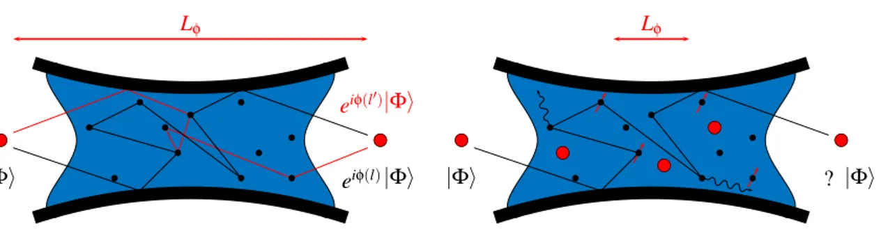
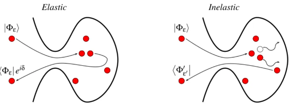
Mesoscopic physics can be viewed as the study of transport and manipulation of electrons in solid-state systems in analogy with photons in vacuum. A major goal in this field is to observe and control quantum coherence effects on macroscopic quantities, such as the electric cur-rent in engineered on-chip devices. The main challenge is to preserve the phase-coherence of electron wave packets when flowing through a conductor. This means that the only effect for the wave packet |Φ〉 of an electron traversing the conductor is to add an overall phase φ(l) depending on the path l which has been covered. The general idea is pictured in Fig. I. As a quantum particle can cover coherently different paths simultaneously, the wave-packet can acquire different phases, engendering interference effects typical of quantum mechanics.
The possibility to realize this situation is non-trivial for electrons propagating in solid-state devices such as semi-conductors. There are various physical effects responsible for the loss of phase-coherence and they are partly pictured on the right part of Fig. I. Decoherence is essentially caused by the interaction of electrons with their environment. This includes in-teractions with other electrons, magnetic impurities and the phonons corresponding to the vibration modes of the underlying crystal. This does not prevent to define a typical length scale below which electrons keep their phase coherence. This quantity is the phase
coher-ence length Lφ[1] and defines the mesoscale: the domain of validity of all the experimental
and theoretical studies carried out in mesoscopic physics. The interest in observing phase-coherent phenomena on electron transport has then spurred the technological progress of these last thirty years in nano-fabrication, to clean samples, and cryogenics, to lower temper-atures down to the milli-Kelvin. Electron-electron interactions are a fundamental obstacle to the preservation of coherence in bulk metals at very low temperature. They affect the
b c bc |Φi eiφ(l)|Φi eiφ(l′)|Φi bc bc bc bc bc bc bc bc bc bc bc Lφ b c bc b c b c b c |Φi ? |Φi bc bc bc bc bc bc bc bc bc bc bc Lφ
Figure I: Left) Ideal situation of mesoscopic physics. If phase coherence is preserved, the only effect on the wave function |Φ〉 of electrons propagating in a solid-state system (here a 2DEG) is to acquire a well-defined phase φ(l). This phase depends on the path l which has been covered. Quantum particles can cover coherently different paths at the same time, leading to different phases which are responsi-ble for the interference effects typical of quantum mechanics. Right) Effects responsiresponsi-ble for the loss of quantum coherence, essentially electron-electron / electron-phonon / electron-magnetic disorder inter-actions. All these processes cause decoherence on typical length scales L′. It is then possible to define a phase-coherence length Lφ≪ L′below which electron propagation is phase coherent.
quasi-1D systems the decoherence time scales with the temperature as [2] 1
τφ= AT
2/3
+ BT3, (i)
with A and B non-universal parameters depending on the sample. The first term, which dominates at low temperatures, corresponds to the dephasing caused by electron-electron interactions, while the second term, governing the behavior of τφat high temperatures,
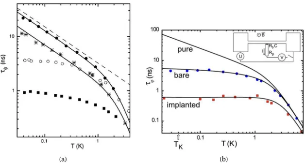
cor-responds to the dephasing caused by electron-phonon interactions. The experimental va-lidity of Eq. (i) was proven in Ref. [3] by performing magneto-resistance measurements on quasi-1D metallic wires composed of different metals. The results are reported in Fig. 2(a). The saturation of the coherence time at lower temperatures is caused by the interaction of electrons with magnetic impurities [4, 5, 6], leading to Kondo physics1, see Fig. 2(b). For
disordered samples, the propagation of electron wave packets is diffusive and the phase co-herence length is given by the diffusion relation
Lφ=
q
Dτφ, (ii)
where D = vFle/d is the Einstein relation for the diffusion constant D, with vF being the
Fermi velocity, le the mean-free path and d the dimensionality of the sample. Looking at
Figs. 2(a) and 2(b), we can consider phase-coherence times of the order τφ∼ 10 ns. In the
experiment of Ref. [5], D ∼ 0.029 m2/s and Eq. (ii) sets a phase coherence length Lφ∼ 1 µm.
INTRODUCTION iii
(a) (b)
Figure II: a) Measurements of the phase coherence time τφfrom the magneto-resistance measurements in Ref. [3]. Measurements are carried out for wires composed of silver (•), less pure silver (◦), gold (∗) and copper (■) and they are compared to Eq. (i). The dashed line plots the first term in Eq. (i), while
the behavior at large temperatures is governed by the second term in Eq. (i). The coherence times are in extremely good agreement with Eq. (i) for silver and gold, while sizable deviations are observed at small temperatures for the less pure silver and copper. b) Same measurements from Ref. [5] carried out for different silver wires with different manganese (Mn) doping, “bare” and “implanted” respectively. The behavior of the coherence time is different from the “pure” behavior described by Eq. (i). The “bare” and “implanted”solid lines fit the experimental data if the corrections to Eq. (i) brought by Kondo correla-tions are taken into account [4, 6]. TK is the Kondo temperature.
For the purposes of this Thesis, the case of the two-dimensional electron gas (2DEG) is es-pecially relevant. It was involved in the first experimental realization of the quantum RC circuit [7, 8], that we address theoretically in this Thesis. For a 2DEG, the first term of Eq. (i) vanishes linearly with the temperature T [9]. For a perfectly clean sample (kFle≫ 1) the
propagation of electrons is ballistic and the phase coherence length is then obtained from the phase coherence time τφthrough the relation
Lφ= vFτφ. (iii)
In the experimental conditions of Refs. [7, 8], at T = 1 K, Lφwas estimated to be of the order
of ∼ 200 µm, while samples are of the order of ∼ 10 µm. Below these length scales, the prop-agation of electrons is phase coherent. One of the first and most striking demonstrations of emergent phase coherent phenomena in the quantum transport of electrons was given by Webb and collaborators in their works starting in 1985. Measuring the conductance of a
Figure III: Aharonov-Bohm effect on the conduc-tance of a mesoscopic circuit. Left) Experiment of Ref. [11]. The conductance of a gold ring oscil-lates as a function of the magnetic field, with pe-riodicity fixed by Φ0= 2φ0, twice the quantum of flux φ0= h/2e through the ring. The oscillations result in a pronounced peak in the Fourier trans-form. Right) Experiment of Ref. [12]. The peak appears even for a ring external to the circuit, a sign of the non-locality of quantum transport.
Figure IV: Conductance quantization in 2DEGs connected by a QPC. The conductance increases by finite quanta of 2g0 = 2 × e2/h as a function of the applied gate voltage Vg on the QPC. The factor 2 comes from spin degeneracy of electrons. A scanning probe microscope measures the local conductance of electrons, accessing local proper-ties of quantum coherent transport. All images are extracted from Ref. [13].
gold ring as a function of the magnetic field, they observed periodical oscillations by varying the magnetic flux inside the ring [10, 11], see Fig. III. This was a clear consequence of the Aharanov-Bohm effect on the electron transport in the gold wire, an exquisite phase coher-ent effect. They also pointed out the non-locality of quantum transport. They showed that the conductance of a phase-coherent circuit is sensitive to the magnetic flux through an ex-ternal connected ring [12], as pictured in Fig. III, which has no classical counterpart. This engendered a real change of paradigm in the theory of quantum circuits with respect to clas-sical ones. The conductivity, a local quantity, lost its interest with respect to the conductance of the whole device, sensitive to non local effects. We mention in passing that recent exper-iments, reported in Fig. IV, imaging spatial current paths with scanning probe microscopes [13, 14, 15], motivate a renewed interest in local properties of quantum transport [16].
Another striking manifestation of quantum coherence effects in mesoscopic devices is conductance quantization. The most paradigmatic example involves 2DEGs separated by a quantum point contact (QPC) [17, 18], also illustrated in Fig. IV. 2DEGs are realized by confining electrons along a spatial dimension in the quantum well which can be engineered at the contact between two different hetero-structures (Ga-As and Ga-Al-As in Refs. [7, 8]). A
INTRODUCTION v
QPC is realized by putting on top of the 2DEG two metallic plates as sketched in Fig. IV. When charged with a negative potential, these plates deform the underlying electron gas control-ling its shape. The gas can be cut in two and electron transfer is possible only by tunnel effect. These mesoscopic constrictions are much smaller than Lφand current flows through
them violating Ohm’s law. The conductance of the system does not increase linearly with the applied bias, but by universal quanta of g0= e2/h, multiplied by a factor two if electrons
are spin degenerate. Analogously, the same phenomenon is observed by gradually opening the QPC at fixed bias, see Fig. IV. Alternative experiments observe the same phenomenon by mechanically breaking the contact between two bulk metals up to reducing it to a single atom [19], in quantum wires [20] and carbon nanotubes [21].
A further remarkable manifestation of the quantum of conductance g0arises for the
con-ducting edges of topological insulators [22]. These exotic states of matter are characterized by the non-trivial topology of their band structure, quantified by the Chern invariant [23]. The transition from a topological to a trivial insulator, as the ionic insulator, where all elec-trons are bond to nuclei, enforces the closing of the gap at the boundaries. A robustly quan-tized number of zero energy states appears then at the edges. Whereas the bulk remains insu-lating, they are conducting channels, which were first observed in 2DEGs under strong per-pendicular magnetic fields as a manifestation of the integer [24] and fractional [25] quantum Hall effect. The integer quantum Hall edges are pictured in the framework of the quantum RC circuit in Figs. V and VI. Their conductance is g0and they are chiral, that is charge
carri-ers can move only in one sense depending on the orientation of the perpendicular magnetic field. The discovery of non trivial topological states of matter in the absence of a magnetic field, giving rise to the quantum spin Hall effect [26, 27], has completely revitalized the field. The restoring of time-reversal symmetry and spin-orbit coupling for electrons are respon-sible for the appearance of two helical counter-propagating edge modes at the boundaries. In these states electrons of opposite spin flow in opposite directions. Pure spin currents can be observed without a net charge flow. This could provide further implementation of the quantum RC circuit that we outline in the Conclusion.
All these experiments deal with the stationary properties of quantum transport, which is conveniently described by the Landauer-Büttiker scattering theory. This theory describes electron propagation as diffusive wave packets [28, 29, 30] and we illustrate it in Chapter 1. Recent technological progress paved the way to the possibility of controlling and probing in real time the phase-coherent evolution of quantum devices such as quantum dots and super-conducting circuits, an important requirement for the implementation of quantum informa-tion protocols. The engineering of local Coulomb potentials in semiconductors succeeded in manipulating single electrons and spins confined in the three spatial dimensions. Regions of confinement can reach the order of the nano-meter and behave as highly tunable artificial impurities, so called quantum dots. Quantum dots can be engineered by confining regions of
the order of the µm in 2DEGs [31], or by connecting leads with carbon nanotubes [32] or sin-gle atoms [33], see Fig. VII. Since the pioneering proposal by Loss & DiVicenzo [34], coupled single-electron quantum dots have been revealed to be promising candidates to become the building block of a quantum processor. In spite of the stronger coupling of solid-state qubits to their electronic environment, the possibility to perform fast operations (frequen-cies above the GHz) on these systems [35] allows for the coherent manipulation of coupled electron spins [36]. This same issue is being addressed with different devices in the field of circuit quantum electrodynamics (Circuit-QED). These architectures [37] involve two-level artificial atoms composed of superconducting Josephson junctions coupled to photon res-onators. These on-chip systems compete nowadays with experiments performed with real atoms in cavity-QED setups [38, 39]. Coherence and relaxation times of the order of the µ-second have been reached for transmon qubits [40], arbitrary quantum states of light can be synthesized in the resonator [41] and the trajectories of the qubit stabilized relying on quan-tum feedback [42]. Quanquan-tum dot circuits and circuit-QED architectures have been recently cross coupled in new experimental setups. On-chip microwave resonators are coupled to quantum dots, allowing for the simultaneous and entangled measurement of electron and photon transport in phase-coherent nanodevices [43, 44, 45, 46], see also Fig. VIII.
In this framework, it is an important task to investigate the typical time scales governing the dynamics of single electrons in quantum coherent devices. This problem has been di-rectly addressed by the theoretical and experimental study of the quantum RC circuit. Its first experimental realization, carried out at the Laboratoire Pierre Aigran (LPA) in 2006 by Gabelli and collaborators [7], is pictured in Fig. V. A two-dimensional electron gas in a strong per-pendicular magnetic field is in the integer quantum Hall regime. Only the edge states of the sample allow for electron transport and exchange coherently electrons with a quantum dot through a quantum point contact. A metallic gate is placed on top of the quantum dot with-out the possibility of exchanging electrons with it. The peculiarity of this system is that it does not allow for the stationary transport of current. A current can be measured only when the system is dynamically driven by a time-dependent gate potential. In Chapter 1, we discuss in detail that, when driven at low frequencies, the system has the same behavior as a classic RC circuit. For this reason, the device of Fig. V is also called the mesoscopic capacitor. This de-vice has remarkable properties, predicted in the seminal works by Büttiker and collaborators [48, 49, 50, 51, 52]. It displays a quantum capacitance Cq= e2N (Ef), proportional to the
lo-cal density of states N (EF) in the quantum dot at the Fermi energy EF. Its resistance is called
the charge relaxation resistance and it is universally quantized to Rq = h/2e2≃ 12.9 kΩ, see
also Figs. 1.5 and 1.6. The interest in this last quantity resides in the fact that its value is dif-ferent from that observed in direct current (DC) experiments RDC= h/De2, which depends
on the transparency D of the quantum point contact. Rqis then a new fundamental quantity
INTRODUCTION vii
Figure V: Experimental realization of the quan-tum RC circuit [7]. The integer quanquan-tum hall edge states of a two-dimensional electron gas exchange electrons through a quantum point contact with a quantum dot. The quantum dot is coupled ca-pacitively to a top metallic gate driven by the gate voltage Vg. The charge relaxation resistance of the circuit is universally quantized to Rq= h/2e2. Courtesy of David Darson, LPA.
Figure VI: Hong-Ou-Mandel interference experi-ment from Ref. [47]. In the top-right, the work-ing principle of the quantum RC circuit as a sin-gle electron emitter (see main text). Electrons are emitted with a time delay τ on the same QPC working as a beam splitter. In the bottom-right, the fermionic nature of electrons causes a sup-pression of the current noise when electrons ar-rive on the QPC at the same time.
is a consequence of the violation of the classical Kirchhoff’s laws in phase coherent devices. This is a further example of the non-locality of electron transport in phase-coherent devices: the conductance of a resistive circuit component (the quantum point contact) is different whether the systems is driven by a DC or an AC bias. This device has also been suggested to be relevant for the non-invasive charge readout in quantum dot devices [53] and for the detection of topological excitations [54, 55]. The RC time of the circuit provides a time-scale for the electron coherent dynamics. The investigation of the mesoscopic capacitor in the non-linear regime has revealed an efficient tool for the triggered emission of single electron wave packets [56]. Its working principle is illustrated in Fig. VI. A sudden variation of the gate potential Vg quenches the discrete levels of the dot, causing the time-controlled emission of
an electron in the nearby integer quantum Hall edge. A variation of the opposite sign of Vg
brings the same level below the Fermi energy, ensuring the emission of a hole in the edge. This led to the realization in nanodevices of the electron analog of quantum optics experi-ments previously done with single quantum particles in the vacuum, that is Hanbury-Brown and Twiss [57, 58] and Hong-Ou-Mandel [47] interference experiments, see Fig. VI.
This Thesis addresses the problem of the effect of electron-electron interactions in the quantum dot on the conduction properties of the quantum RC circuit. Quantum dots are almost zero-dimensional structures in which electrons are close to each other and Coulomb
∆V Vg
Figure VII: Top) Quantum dots engineered by putting negatively charged metallic plates on top of a 2DEG. The first two images are extracted from Ref. [31]. Bottom) Coulomb blockade observed for the conductance through a quantum dot com-posed of silicon atoms exchanging electrons with leads [33]. Restricting to the case of small VSD biases, the conductance is completely suppressed for a quantized number of charges on the dot and displays a peak at the charge degeneracy points.
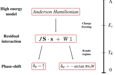
Resonator Conductance Phase-shift Vg Kondo singlet Source Drain Gate
Figure VIII: Kondo effect in direct transport exper-iments. A Kondo ridge arises at zero bias VSD in the conductance when a single electron is con-fined in the quantum dot. We signal also the sensitivity of photons to Kondo electronic correla-tions in quantum dot circuits. The phase-shift of the signal in a microwave resonator capacitively coupled to a quantum dot has the same behav-ior as the electronic conductance through it (in-sets from Ref. [43]).
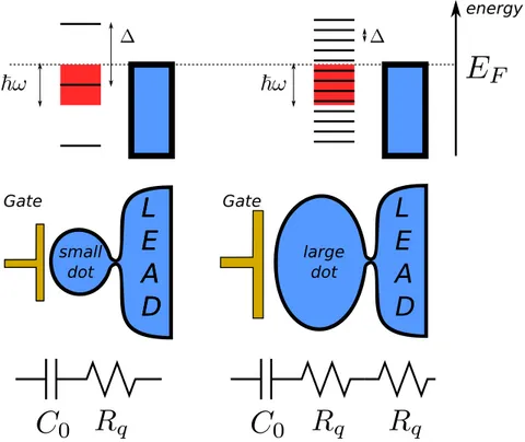
screening is less effective. Interactions on the quantum dot are controlled by the charging
energy Ec, the energy required to add a charge on the dot. The experimental measurements
at the LPA were carried out for Ec ≪ ∆, ∆ being the energy level spacing on the quantum dot,
and driving frequencies ħω ∼ Ec. In these conditions a mean-field approach for interactions
justifies the original scattering approach of Refs. [48, 49, 50, 51, 52]. The issue of considering strong interactions is promising if we refer to the striking effects they already have on direct transport experiments. The most paradigmatic effect is Coulomb blockade [59]. It arises in quantum dots connected to biased macroscopic electron reservoirs through quantum point contacts, see Fig. VII. The applied gate voltage VG and strong Coulomb interaction allow to
set a quantized number of electrons on the quantum dot [60], see also Fig. 3.1. For tempera-tures and applied bias voltages much lower than the charging energy Ec, incoming electrons
on the quantum dot do not have enough energy to change the charge on the dot. This results in the suppression of the conductance through the device, with the exception of the charge degeneracy points in which two different charge occupations on the dot become degenerate in energy, see Fig. VIII. This phenomenon cannot be explained by the single-body perspec-tive of scattering theory. The charge occupation on the dot triggers the current transfer by electron-electron interactions. A direct treatment of these interactions on the dot is then
INTRODUCTION ix
required. The quantum RC circuit of Fig. V is described, in the simplified case of spinless electrons, by the Coulomb blockade Hamiltonian [60]
HCBM=X kσ εkckσ† ckασ+X lσ εldlσ† dlσ+ tX klσ ³ ckσ† dlσ+ dlσ† ckσ ´ + Ec( ˆn − N0)2, (iv)
where free electrons of dispersion εk can tunnel in a multilevel quantum dot through the
channel σ. The last term describes the capacitive coupling Cg between the dot and the top
metallic gate, controlled by the charging energy Ec = e2/2Cg. For large charging energies,
this coupling forces the local quantized number of charges ˆn = Plσdlσ† dlσto be as close as
possible to the classical occupation of the top metallic gate controlled by the gate voltage
N0= CgVg/e, see also Fig. 3.1. The extension to the situation with two leads of Fig. VII is
readily obtained considering more reservoirs in Eq. (iv).
Even more interesting is the spinful case, giving rise to one of the most paradigmatic many-body phenomena in mesoscopic physics, the Kondo effect [61]. Spin exchange between a single-electron charged quantum dot and itinerant electrons leads to the emergence of many-body Kondo anti-ferromagnetic correlations. The increase of the electronic conduc-tance caused by the opening of the Kondo channel in Coulomb blockade regimes demon-strates the possibility to study many-body phenomena in mesoscopic physics [62, 63, 64], see also Fig. VIII. This phenomenon is captured by the Anderson model
HAn=X kσ εkσc†kσckσ+ tX kσ ³ ckσ† dσ+ dσ†ckσ ´ + εdX σ ˆ nσ+U ˆn↑nˆ↓, (v)
describing 1/2 spin electrons tunneling inside a single-level interacting quantum dot. The determination of the admittance of the quantum RC circuit obeying to these Hamiltonians is the purpose of this Thesis. This problem has already received a large attention in re-cent works. The electron dynamics in the presence of interactions in the dot [65, 66] and its spin/charge separation [67] have been studied. For small metallic islands the problem has been addressed at intermediate temperatures [68] and in the many channel case [69]. In particular, the two-channel case has been argued to exhibit non-Fermi liquid behavior [70, 71]. The universality of Rq still holds if interactions in the dot [72] or not too strong
interactions in the lead [73, 74] are taken into account in an exact manner. Increasing the size of the dot results in a mesoscopic crossover for Rq from h/2e2to h/e2[72]. For strong
enough interactions in the lead, i.e. a Luttinger parameter below 1/2, the system undergoes a Kosterlitz-Thouless phase transition to an incoherent regime where Rq is no longer
quan-tized [73, 74]. The main problem was to understand for which reason the charge relaxation resistance showed the same universal behavior as if interaction did not play any role, recov-ering, surprisingly, the results of scattering theory even in Coulomb blockade regimes. In this Thesis we provide a general Fermi liquid theory to describe the dynamics of low energy electrons in the quantum RC circuit for systems governed by the Hamiltonians Eq. (iv) and
generalized SU(N) symmetric versions of Eq. (v). Our main achievement is the proof that a generalized Korringa-Shiba relation [75] gives the condition to observe a universal charge relaxation resistance even in the presence of strong interactions on the dot at zero temper-ature. The study of this formula for spinful electrons in the presence of a magnetic field allows us also to describe analytically the emergence of a giant charge relaxation resistance caused by the destruction of Kondo correlations, in agreement with previous Hartree-Fock [66] and numerical renormalization group results [76]. Moreover, the analytical renormaliza-tion group approaches developed in this Thesis can be also extended to more exotic devices displaying SU(4) symmetries. In particular, we derive an analytical expression for the SU(4) Kondo temperature.
Here follows the structure of the Thesis:
Chapter 1 We discuss the original scattering approach of Büttiker and coworkers [48, 49, 50, 51, 52] to describe the quantum RC circuit and make the link with the Hamilto-nian approach adopted in this Thesis. This will allow us to define the differential capacitance C0, connected to the static charge susceptibility of the quantum dot,
and introduce the link between charge relaxation resistance universality and the Korringa-Shiba relation.
Chapter 2 We give a general and heuristic overview of our approaches and results. In par-ticular, we demonstrate how a Fermi liquid approach consistent with the Friedel sum rule [77] allows us to derive a generalized form of the Korringa-Shiba re-lation and predict non-universal behaviors for the charge relaxation resistance when both the SU(2) symmetry and the particle-hole symmetry are broken. Chapter 3 The low energy Fermi liquid fixed point discussed in Chapter 2 is explicitly
de-rived by applying analytical renormalization group techniques and with the help of a new representation of the Coulomb blockade model Eq. (iv) with slave-states.
Chapter 4 The demonstration of Chapter 3 is extended to the Anderson model Eq. (v), with the additional difficulty of dealing correctly with diverging Kondo correlations. Relying on the exact solution of this model provided by the Bethe ansatz [78, 79], we test our Fermi liquid approach in the whole region of parameters and fully characterize the behavior of the giant charge relaxation resistance and the quantum capacitance.
Chapter 5 We extend our Fermi liquid approach to describe the behavior of the charge re-laxation resistance in SU(4) symmetric quantum dot circuits in the presence of a magnetic field. We rely on renormalization group techniques to derive the SU(4) Kondo temperature and the dot occupation in the Coulomb blockade regime.
INTRODUCTION xi
The work presented in this Thesis led to three publications
1. Filippone Michele, Le Hur Karyn, Mora Christophe : Giant Charge Relaxation Resis-tance in the Anderson Model, Physical Review Letters 107, 176601 (2011) ,
2. Filippone Michele, Mora Christophe : Fermi liquid approach to the quantum RC cir-cuit: Renormalization group analysis of the Anderson and Coulomb blockade models, Physical Review B 86, 125311 (2012) ,
3. Filippone Michele, Le Hur Karyn, Mora Christophe : Admittance of the SU(2) and SU(4) Anderson quantum RC circuits, Physical Review B 88, 045302 (2013) .
CHAPTER
1
THEORY OF THE QUANTUM RC CIRCUIT:
NON-INTERACTING CASE
Contents
1.1 Phenomenology . . . . 2 1.2 Scattering theory of the quantum RC circuit . . . . 3 1.2.1 The quantum capacitance . . . 7 1.2.2 The charge relaxation resistance . . . 9 1.2.3 The example of a quantum RC circuit with a 2DEG . . . 10 1.3 Hamiltonian description of the quantum RC circuit . . . 11 1.3.1 Linear response theory: basic notions for the quantum RC circuit . . . 12 1.3.2 Description of the quantum RC circuit with a resonant level model . . 14 1.4 Conclusions . . . 18
In this chapter the results of the seminal works of Büttiker, Thomas and Prêtre [48, 49, 50, 51, 52] are presented. They were the first to address theoretically the mesoscopic capacitor as the quantum analog of a classical RC circuit, an analogy detailed in Section 1.1. Their work is based on the Landauer-Büttiker scattering formalism [28, 30, 29], discussed in Section 1.2. The scattering approach describes the dynamics of lead electrons and treats the mesoscopic capacitor as a sort of “black box” in which electrons propagate coherently and escape with a well defined phase. Büttiker, Thomas and Prêtre introduced the quantum capacitance Cq,
a new capacitive contribution in series with the geometrical capacitance Cg. The quantum
capacitance reflects the spectral structure of the quantum dot. One of the key results of these authors was to predict a universal charge relaxation resistance Rq= h/2e2, regardless of the
Top view
Side view
Figure 1.1: Schematic representation of the quantum RC circuit. Left) View from the top: electrons in the edge states of a two dimensional electron gas in the integer quantum Hall regime can tunnel inside a quantum dot through a quantum point contact. The dot is driven by a top metallic gate. Right) The dot and the gate are separated by an insulator. The two components cannot exchange electrons, forming the two plates of a capacitor C . The quantum point contact controls the transmission of electrons, giving rise to a resistance R. These two circuit elements are in series, and define a quantum coherent RC circuit.
opening of the quantum point contact. This result is in striking contrast with the resistance measured in DC experiments. An alternative approach to derive the results of scattering theory is presented in Section 1.3. It is based on the Hamiltonian description of the quantum RC circuit, considering explicitly the internal structure of the quantum dot. In Section 1.3.1, we discuss how linear response theory links the mesoscopic admittance of the quantum RC circuit to the dynamical charge susceptibility χc(ω) of the quantum dot. We show that the
capacitance is actually given by the differential capacitance C0, proportional to the static
charge susceptibility of the dot and that charge relaxation universality relies on the Korringa-Shiba relation [75]. Both these results will predict non-trivial behaviors in the interacting case. In Section 1.3.2, we illustrate how these quantities and relations can be readily obtained for a simple non-interacting resonant level model, recovering the results of scattering theory. This allows us to introduce the path integral formalism, largely exploited all along this text.
1.1 Phenomenology
The heuristic argument that motivates the study of the device pictured in Fig. V as the quan-tum analog of a classical RC circuit is clarified in Fig. 1.1. The metallic gate on top of the quantum dot cannot exchange electrons with it. These two components, the first one
de-1.2. SCATTERING THEORY OF THE QUANTUM RC CIRCUIT 3
scribed by a classical theory and the second one quantum coherent, constitute the two plates of a capacitance on which electrons accumulate following the variation of the gate potential
Vg. The value of this capacitance will depend on the geometry of the contact and, in the
experiment of Ref. [7], the geometrical capacitance Cg was estimated to be of the order of
∼ 10−100 fF. This capacitance is in series with a quantum point contact. The direct transport measurements [17, 18], discussed in the Introduction, show that this behaves as a resistive element, whose resistance is given by
RDC= h
e2D, (1.1)
where D is the transparency, to be defined through scattering theory in Section 1.2. This quantity depends on the probability r for electrons to be backscattered when arriving at the tunnel barrier constituted by the quantum point contact. D therefore depends on the open-ing of the quantum point contact. These considerations explain why the device in Fig. 1.1 can be viewed as an RC circuit. The admittance of a classical RC circuit reads
G(ω) = −i ωC
1 − iωRC . (1.2)
For the following discussion, it is useful to expand this expression to second order in the frequency ω
G(ω) = −iωC¡1 + iωCR¢. (1.3)
The question is then to establish whether the admittance of the device in Fig. V respects the RC structure of Eq. (1.3) when quantum coherence effects are considered for electrons. We will see that it is the case.
1.2 Scattering theory of the quantum RC circuit
Coherence effects between electrons, in the absence of interactions, are fully taken into ac-count by scattering theory [28, 30]. The principle of this approach is sketched in Fig. 1.2. Let us consider a two-dimensional spinless electron gas as the one pictured in Fig. 1.2. A difference of potential δV = µL− µR is applied between the left and right metallic contacts.
It coincides with the difference of their respective chemical potentials µα=L,R = EF+ eVL,R, EF being the Fermi energy that, from now on, we fix to zero. It is a fundamental assumption
of the scattering formalism to consider the electron reservoirs (the metallic leads) to be at
equilibrium. This implies that the energy distribution of electrons emitted from the leads
obeys the Fermi-Dirac distribution
fα(ε) =
1
Figure 1.2: Principle of scattering theory for a two-dimensional electron gas. Thermalized leads of chemical potential µα=L,Remit electrons towards the phase coherent region smaller than Lφ. The oper-ators aαare associated to the state of these electrons, which are emitted back to the leads in the state bα as a unitary superposition of the incoming modes.
An operator aα,n(ε) is associated to every electron in the state n of energy ε, entering the
mesoscopic region from the reservoir α. An operator bα,n(ε) is associated to every mode n of energy ε coming out of the mesoscopic region joining the reservoir α. This assumes
implicitly the hypothesis that there exist ideal regions between the mesoscopic scatterer and the reservoirs in which electrons propagate freely without any backscattering in the state n. Scattering theory is characterized by the fundamental assumption that the only effect of the mesoscopic region on incoming states, described by aα,n(ε), is a unitary evolution. This is
formally stated with the help of the scattering matrix S(ε) defined by
µ £b L¤ £bR¤ ¶ = µ £s LL¤ £sLR¤ £sRL¤ £sRR¤ ¶ µ £a L¤ £aR¤ ¶ . (1.5)
£aα¤ and £bα¤ are the vectors collecting all the modes n in the ideal region between the
reser-voir α and the mesoscopic scatterer. Unitary evolution is fulfilled by imposing the unitarity of the scattering matrix SS†= S†S = 1. We stress that the matrix S(ε) relates modes with the same energy ε. This translates the fact that all processes considered in the mesoscopic
scat-terer are elastic. They do not modify the energy of electrons, excluding the inelastic processes which could be caused by interactions. The expression for the current operator Iαflowing
in the reservoir α is readily derived as a difference between the ingoing and outgoing states [1, 80] Iα(x, t) = e h Z dεdε′ha† α(ε)aα(ε′) − b†α(ε)bα(ε′) i ei (ε−ε′)(t−x/vF)/ħ, (1.6)
1.2. SCATTERING THEORY OF THE QUANTUM RC CIRCUIT 5
with vF the Fermi velocity. Applying Eq. (1.5) the stationary conductance is given by
gLR(ω = 0) = −〈IL〉 δV = e2 h Z dεTrn£sLR(ε)¤†£sLR(ε)¤ o · fL(ε) − feδVR(ε). (1.7) In the linear regime δV → 0 it becomes
gLR(ω = 0) =e 2 h Z dεTrn£sLR(ε)¤†£sLR(ε)¤ o · µ −∂ f ∂ε ¶ =e 2 hD , (1.8)
where we applied the relation −∂f /∂ε = δ(ε − EF), valid at zero temperature. This result
provides the formal definition of the transparency D of the scattering region, which we in-troduced for the DC resistance (the inverse of the DC conductance) in Eq. (1.1)
D = Trn£sLR(EF)¤†£sLR(EF)¤
o
. (1.9)
This quantity encodes all information about the backscattering and transmission of elec-trons in the mesoscopic region. Eqs. (1.8) and (1.9) constitute the notorious
Landauer-Büttiker formula, a powerful tool to describe electron transport in a variety of situations in
mesoscopic physics. As an example we discuss the case of the QPC in a 2DEG of Fig. IV. In the single channel case, that is for a single electronic state traversing the QPC, the S-matrix reads S = µ r t t r ¶ , (1.10)
where r and t are the back-reflection and transmission amplitudes for electrons coming on the QPC. Eq. (1.9) states that D = t2, the probability for electrons to pass through the QPC. The progressive opening of the QPC governs the transition D = 0 → 1, explaining the transi-tion of the conductance from 0 to e2/h in Fig. IV. The progressive opening of further channels give rise to the other steps of the conductance always present in Fig. IV.
This formalism can be adapted to the case of the mesoscopic capacitor in Fig. V. A main difference is the “mixed” nature of the quantum RC device, which is highlighted in Fig. 1.3. The quantum RC circuit is composed of a phase-coherent part (the two-dimensional elec-tron gas + the quantum dot) in direct contact to an incoherent one (the top metallic gate). Moreover, these constituents cannot exchange electrons, preventing a direct current. To ob-serve electron transport, the system must be driven dynamically. This is operated by apply-ing a gate potential oscillatapply-ing periodically in time
Vg(t) = Vg+ εωcos(ω t). (1.11)
For small oscillation amplitudes εω, the Landauer-Büttiker formalism allows for the
calcula-tion of the circuit admittance within linear response theory, to be discussed in Seccalcula-tion 1.3.1. In the case of a single conduction mode, this reads [49]
gL(ω) =e 2 h Z dεTrh1 − s†(ε)s(ε + ħω)i·f (ε) − f (ε + ħω) ħω . (1.12)
Potential
rescaling
Figure 1.3: The blue region composed of the two-dimensional gas is phase coherent, that is its size L ≪ Lφ. The top metallic gate is incoherent and driven by a time-dependent gate potential Vg(t) inducing an unknown uniform potential U (t) on the dot. To compute the admittance of the phase coherent device, all energies have to be shifted by −U(t), allowing for the classical circuit analogy in the top right. The admittance of the whole device results as a series of a charge relaxation resistance Rq and the electro-chemical capacitance Cµ, composed of the series of a quantum capacitance Cq and the geometrical capacitance Cg.
For one channel, the matrix s(ε) reduces to a pure phase s(ε) = ei η(ε), as the electrons entering
the dot come back to the lead with unit probability. This phase is related to the dwell-time that electrons typically spend in the quantum dot, defined from the scattering matrix as a Wigner-Smith delay time [81, 82]
τ(ε) h = 1 2πis †(ε)d s(ε) dε = 1 2π dη(ε) dε . (1.13)
The interpretation of τ as a dwell-time will become clear in a forthcoming example. Applying this definition to the calculation of Eq. (1.12) in the limits T → 0 and ħω → 0, we find
gL(ω) = −iωe 2 h · τ +12i ωτ2+O¡ω2¢ ¸ . (1.14)
The dwell-time τ = τ(0) is considered at the Fermi energy. Notice that this expression has the same structure as Eq. (1.3) for the RC admittance of a classical circuit. Matching Eq. (1.14) with Eq. (1.3), one finds
Cq=e
2
h τ , Rq=
h
1.2. SCATTERING THEORY OF THE QUANTUM RC CIRCUIT 7
The characteristic time that an electron spends in the quantum dot is given by τ = 2RqCq,
twice the RC time because it includes the charging and relaxation time of the RC circuit. We notice the emergence of a universally quantized relaxation resistance, regardless of any microscopic detail of the quantum RC circuit, in contrast with the DC formula Eq. (1.1).
Before discussing these two quantities in detail, we would like to stress that the interpre-tation of the device in Fig. V as a quantum analog of an RC circuit strictly holds at low fre-quencies. Taking into account higher frequencies forces to introduce inductive constituents if one wants to persevere with a classical circuit analogy [83]. Moreover, when the same system is driven by large pulses of the gate potential as in the single-electron experiments of Ref. [56, 57, 47], discussed in the Introduction, the linear response regime is definitively abandoned and the resistance and capacitance computed here are not relevant anymore.
1.2.1 The quantum capacitance
The effect of the geometrical capacitance Cg has been left aside in the previous discussion
of the scattering formalism. The admittance Eq. (1.12) has been derived by applying linear response theory for the driving potential U (t) in the quantum dot, see Fig. 1.3. Electrons get-ting at different times on the dot are differently phase-shifted, causing a local accumulation of charges responsible for the emergence of quantum capacitive effects, described by Cq.
The time delay of the electron phase with respect to the driving potential U (t) are respon-sible for energy dissipation, controlled by Rq to be discussed in detail in Section 1.2.2. The
subtlety, in the presence of the geometrical capacitance Cg, is that the potential U (t) does
not coincide with the gate potential Vg(t). The situation is pictured in Fig. 1.3: the geometric
capacitance Cg is interposed between the gate and the dot, producing a drop of potential.
This potential drop depends on how Coulomb screening effects renormalize the potential felt by electrons on the dot. In a mean-field or Hartree-Fock treatment, the potential on the dot, denoted U (t), is assumed to be uniform for each electron. This is also equivalent as to assume the random phase approximation (RPA) for interactions between electrons in the quantum dot, which can be justified for not too strong interactions or to leading order in a 1/N expansion, where N is the number of channels connected to the dot [65]. The potential
U can then be determined self-consistently from the constraint of charge/current
conserva-tion throughout the whole device. This requires that the current Idevrunning in the coherent
part of the device is the same as the current Igateflowing in the incoherent metallic gate
I = Idev= Igate. (1.16)
As all potentials are defined with respect to some constant energy, all energies can be shifted by −eU(t), setting the potential to zero in the quantum dot. In this case the currents in the
Figure 1.4: Physical mechanism responsible for the arising of the quantum capacitance Cq. The Pauli exclusion forces electrons coming from the lead in the quantum dot to pay a further energy price equal to the local level spacing ∆. The associated capacitance is then Cq = e2/∆. On the top-right a one-dimensional representation of the quantum RC circuit is provided, involving a dot of size L.
device and in the metallic gate are given by
Idev= −U (ω)gL(ω), Igate= −iCgω£U (ω) −Vg(ω)¤ . (1.17)
Applying the current conservation condition Eq. (1.16), the potential U is eliminated, leading to the admittance of the total device
G(ω) = −VI g = 1 1 gL(ω)+ 1 −i ωCg . (1.18)
Recalling that the low frequency behavior of gL(ω) in Eq. (1.12) is the same as for a classical
RC circuit, given by Eq. (1.3), Eq. (1.18) states that the whole device, including the capaci-tance Cg, can be viewed as an RC circuit. Albeit with two capacitances in series, Eq. (1.18)
nevertheless still gives a universally quantized Rq= h/2e2. The series of Cq and Cg gives the
electro-chemical capacitance Cµ, see Fig. 1.3. This quantity provides the imaginary part of the
RC admittance Eq. (1.3), accessible in experiments. The concept of quantum capacitance and geometric capacitance in series is restricted to a mean-field treatment of interactions. Therefore this circuit description does not hold in the case of interactions.
Once the geometrical capacitance Cg has been included in the formalism, a heuristic
ar-gument clarifies the physical origin of the quantum capacitance Cqas a manifestation of the
fermionic statistics of electrons, more precisely the Pauli exclusion principle. When an elec-tron is added on the quantum dot, in which energy levels are spaced by ∆, the Pauli exclusion principle does not allow for the filling of an energy state already occupied by an other elec-tron, see Fig. 1.4. The fermionic statistics imposes to pay a further energy price ∆ to put a further electron in the dot. The capacitance associated to this process is then
Cq=δQ
1.2. SCATTERING THEORY OF THE QUANTUM RC CIRCUIT 9
For one electron δQ = e and δV = ∆/e. Substituting these two expressions in Eq. (1.19), we recover a uniform quantum capacitance
Cq=e
2
∆ . (1.20)
This expression establishes that the quantum capacitance is proportional to the density of states in the quantum dot at the Fermi energy Cq = e2N (EF). The level spacing of the
quantum dot can be actually estimated and, in the experimental conditions of Ref. [7], it was established to be of the order of ∆ ∼ 15 GHz, corresponding to a quantum capacitance
Cq∼ 1 fF. The experimental measurement of Cµ, plotted in Fig. 1.6, gives an estimate also
for Cg, showing that Cq≪ Cg. This implies that the level spacing ∆ was much larger than the
charging energy Ec = e2/2Cg , of the order of fractions of the GHz, justifying the mean-field
approach to explain the experimental results.
The previous argument applies to the case of perfect transmission r = 0, in which the den-sity of states of the completely open dot is uniform accordingly to Eq. (1.20). Finite reflection
r 6= 0 is responsible for resonant tunneling processes, engendering the oscillatory behavior
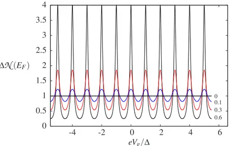
of the local density of states as a function of the gate potential Vg, in agreement with the
experimental findings in Fig. 1.6. All these arguments will be comforted by a quantitative analysis in Sections 1.2.3 and 1.3.2.
1.2.2 The charge relaxation resistance
The predictions from Eq. (1.15) were verified experimentally at the Laboratoire Pierre Aigrain in 2006 [7]. The results are shown in Figs. 1.5 and 1.6. In the quantum coherent regime the charge relaxation resistance is universal. It does not depend on the backscattering proba-bility of electrons at the entrance of the quantum dot. As we considered spinless electrons, the 1/2 factor in Eq. (1.15) has nothing to do with spin degeneracy. It comes from the fact that the dot is connected to a single reservoir in contrast to the source-drain reservoirs in DC transport. The interpretation of Rq as a Sharvin-Imry contact resistance has been disputed
in Refs. [84, 85]. In direct transport, each metallic contact is responsible for a quantized con-tact resistance Rc = h/2e2, the Sharvin-Imry resistance [86, 87]. Eq. (1.1) should be recast in
the form RDC= h 2e2+ h e2 1 − D D + h 2e2, (1.21)
to highlight the resistive contribution strictly associated to the quantum point contact RQPC=
h/e2·(1−D)/D and that of the contacts Rc. The reason for the universality of Rqin Eq. (1.15)
is that each electron emitted by the unique lead keeps its coherence until it goes back to it. To recover the DC result Eq. (1.21) in an AC measurement, electrons have to loose completely
Figure 1.5: Experimental measurement of the charge relaxation resistance (coinciding with the real part of the impedance Z ) in two different samples as a function of the quantum point con-tact potential V , which affects also the gate po-tential Vg. Measurements were carried out for T = 30mK and B = 1.3T . The charge relaxation resistance is shown to be universally fixed to Rq= h/2e2 within the uncertainties indicated by the hatched areas.
Figure 1.6: Experimental measurements of the electrochemical capacitance Cµ(series of Cg and Cq) for the same samples and the same experi-mental parameters as in Fig. 1.5. This coincides with the imaginary part of Z . The oscillatory be-havior as a function of Vgis related to the density of states in the dot and is qualitatively reproduced in Fig. 1.8. The peaks correspond to the resonance of an internal level of the dot (calibrated by Vg, see Eq. (1.29)) with the Fermi energy in the lead.
their phase coherence inside the dot [84, 85]. The high temperature limit kBT ≫ ∆ is not
enough to recover Eq. (1.21), giving a charge relaxation resistance Rq = RDC− h/2e2, still
reflecting the presence of only one reservoir.
1.2.3 The example of a quantum RC circuit with a 2DEG
We provide in this section an application of the formal concepts of the previous discussion. We consider the case of of Fig. 1.1, in which electrons propagate in the integer quantum Hall edges of the quantum dot. This discussion is inspired from Refs. [7, 8, 88]. If l is the circum-ference of the part of the edge state that forms the quantum dot and vd the drift velocity of
the electron, τ0= l/vd is the time needed to cover a tour of the dot. Considering the usual
evolution operator ei H tħ , acting on eigenfunctions of energy ε, an electric wave of energy ε
acquires then a phase φ(ε) = (ε−eU)τ0/ħ, when making a tour of the dot. Notice that we had
to shift the energy ε of the electron by −eU because of the potential shift schematized in Fig. 1.3. The chiral nature of the edge states allows for a one-dimensional representation of the problem, pictured in the right-top of Fig. 1.4. For a quantum well of size L, close to the Fermi energy, the spectrum can be linearized and the level spacing is constant and given by
∆=πħvF
1.3. HAMILTONIAN DESCRIPTION OF THE QUANTUM RC CIRCUIT 11
The dwell-time for electrons of velocity vF is
τ0=2L
vF . (1.23)
Substituting Eqs. (1.22) and (1.23) in Eq. (1.15), we find the uniform quantum capacitance, derived heuristically, of Eq. (1.20). If the reflection amplitude at the entrance of the dot is
r and D = 1 − r2the transmission probability, the dot can be viewed as a Fabry-Perot cavity
and the phase of the out-coming electron is
s(ε) = r − Dei φ(ε)X∞ q=0 rqei qφ(ε)= r − e i φ(ε) 1 − rei φ(ε) = e i η(ε). (1.24)
Applying Eq. (1.13) we obtain the local density of states
N (ε)=τh0 1 − r
2
1 − 2r cos£2π
h¡ε − eU¢τ0¤ + r2
. (1.25)
This is plotted in Fig. 1.8 and reproduces the oscillatory behavior of the capacitance in Fig. 1.6. In the limit of small transmission (D ≪ 1 and r ≈ 1), Eq. (1.25) reduces to a sum of Lorentzian peaks of width ħγ, γ = D/τ0:
N (ε) = 2 πħγ X n 1 1 +³ε−eU −n∆ ħγ/2 ´2. (1.26)
These peaks are the discrete spectrum of the dot energy levels.
To conclude, we mention that the generalization to N modes is readily obtained. The mesoscopic admittance Eq. (1.12) can be still cast into the form Eq. (1.3) with the difference
Cq=e 2 h N X n=1 τn, Rq= h 2e2 P nτ2n ¡P nτn¢2 , (1.27)
in which τnare the dwell-times in the quantum dot of electrons in the n-th mode. We discuss
now how these same results can be derived from a microscopic approach.
1.3 Hamiltonian description of the quantum RC circuit
The aim of this Thesis is to address the effects of interactions on the quantum capacitance and the charge relaxation resistance. To do this, we cannot look anymore at the quantum dot as a sort of “black-box”, but models must be considered that give an exact description of
electron-electron interactions within it. In this section, the results of Section 1.2 are derived from an Hamiltonian approach. We neglect for the moment interactions, which allows for straightforward calculations. We establish the physical origin of the quantum capacitance and the charge relaxation universality from this alternative point of view.
Considering spinless electrons, the Coulomb blockade model Eq. (iv) accounts explicitly for the driving of charges on the dot and interactions. This can be understood by inspecting the part of the Hamiltonian describing the capacitor
HCapa= Ec( ˆn − N0)2. (1.28)
If the square is expanded and constant contributions are neglected, it results in a renormal-ization of orbital energies εl in Eq. (iv) and in an interaction term, namely
HCapa= −eVg(t) ˆn + Ecnˆ2. (1.29)
We take into account explicitly the time dependence of the driving gate voltage to stress that it couples to the charge occupation of the quantum dot ˆQ = e ˆn. We are interested in
calcu-lating the admittance of the system. The current of the whole device is a derivative in time of the charge leaving the quantum dot, the admittance reads then, in Fourier frequency repre-sentation,
G(ω) = −iωVQ(ω)
g(ω). (1.30)
For “small” oscillations εωof the gate voltage Eq. (1.11), the problem can be studied close to
equilibrium, and linear response theory provides the tools to calculate Eq. (1.30).
1.3.1 Linear response theory: basic notions for the quantum RC circuit
Linear response theory [89, 90] addresses the calculation of observables in time-dependent problems which can be written in the form
H = H0− λf (t) ˆA . (1.31)
ˆ
A is a generic operator, f (t) any function of time of order 1 and λ a perturbation parameter.
To first order in λ, the time-dependent corrections to any observable 〈 ˆO〉 can be written as a
functional of operators averaged at equilibrium
〈 ˆO〉(t) = 〈 ˆO〉0+ λ
Z∞
−∞
d t′χ(t − t′)f (t′). (1.32)
The notation 〈·〉0means that the averages are carried out by taking traces involving the