HAL Id: hal-02319959
https://hal.archives-ouvertes.fr/hal-02319959
Submitted on 31 Jul 2020HAL is a multi-disciplinary open access
archive for the deposit and dissemination of sci-entific research documents, whether they are pub-lished or not. The documents may come from teaching and research institutions in France or abroad, or from public or private research centers.
L’archive ouverte pluridisciplinaire HAL, est destinée au dépôt et à la diffusion de documents scientifiques de niveau recherche, publiés ou non, émanant des établissements d’enseignement et de recherche français ou étrangers, des laboratoires publics ou privés.
Rechargeable aqueous electrolyte batteries: from
univalent to multivalent cation chemistry
Rezan Demir-Cakan, M. Rosa Palacín, Laurence Croguennec
To cite this version:
Rezan Demir-Cakan, M. Rosa Palacín, Laurence Croguennec. Rechargeable aqueous electrolyte bat-teries: from univalent to multivalent cation chemistry. Journal of Materials Chemistry A, Royal Society of Chemistry, 2019, 7 (36), pp.20519-20539. �10.1039/c9ta04735b�. �hal-02319959�
1
Rechargeable Aqueous Electrolyte Batteries:
from Univalent to Multivalent Cations Chemistry
Rezan Demir-Cakana,b, M. Rosa Palacinc,e and Laurence Croguennecd,e,f,**e-mail: [email protected]
a Department ofChemical Engineering, Gebze Technical University, 41400, Gebze, Kocaeli, Turkey b Institute of Nanotechnology, Gebze Technical University, 41400, Gebze, Kocaeli, Turkey
c Institut de Ciència de Materials de Barcelona, (ICMAB-CSIC), Campus UAB, 08193 Bellaterra, Catalonia, Spain d CNRS, Univ. Bordeaux, Bordeaux INP, ICMCB UMR 5026, F-33600 Pessac, France.
e ALISTORE-ERI European Research Institute, FR CNRS 3104, F-80039 Amiens Cedex 1, France.
f RS2E, Réseau Français sur le Stockage Electrochimique de l’Energie, FR CNRS 3459, F-80039 Amiens Cedex 1,
France.
Abstract
Water based electrolytes enable very high ionic conductivity, and are particularly attractive for high power density batteries. The main advantages of water-based electrolytes are their lower cost and non-flammability, while their principal disadvantage is the limited thermodynamic electrochemical window of water. Yet, the latter is currently being challenged, through the use of highly concentrated electrolytes, (“water in salt concept”).
Strong research focus is currently placed on rechargeable M-ion batteries (M=Li, Na) mimicking the organic Li-ion or Na-ion, which will despite falling shorter in energy density exhibit cost advantages. Moreover, they should be expected to delivering very attractive power densities. The main challenge at this stage is the development of new negative electrodes able to operate at lower potentials.
A more challenging topic is divalent ion concepts (M=Zn) using a Zn metal anode which could, in principle, deliver higher energy density, but for which issues still remain related to (i) develop appropriate positive electrode materials for reversible Zn ion insertion and (ii) side reactions involving mostly H+ or OH- species, which are not yet mastered.
Key learning points
(1) Featuring the most recent advances in aqueous electrolyte metal-ion battery systems and probing their challenging issues.
(2) Understanding the cell chemistries and underlining their different behaviours in aqueous and non-aqueous media.
(3) Defining cutting-edge characterization tools to investigate the insertion/deinsertion phenomena in water-based electrolytes: reaction mechanisms and side reactions.
2
1. Introduction
Batteries are electrochemical energy storage devices which are used in many applications ranging from mobile to stationary applications and requiring very different energy densities. Batteries are made of two electrodes involving different redox couples that are separated by an ion conducting medium, the electrolyte, typically a liquid with a certain concentration of dissolved salt. Independent of being single-use or rechargeable batteries, upon discharge, electrons transfer from one electrode to the other through the external circuit and charges are compensated by ions’ migration across the electrolyte. If the reaction is reversible, the process can be reversed applying an external current and thus batteries can be recharged. The voltage of the cell depends on the difference in potential between the redox couples involved at the electrodes, while the electrochemical capacity of each given electrode material depends on the number of electrons exchanged per formula weight. The balance between the two electrodes and the product of both magnitudes, voltage and capacity, determines the maximum energy density attainable. The energy stored per mass unit differs from 20 Wh/kg to 250 Wh/kg in commercial cells and depends on both the cell design, which includes the total mass of “inactive weight” such as packaging foils, pole tabs, separators or electrolyte, and the “active weight” as electrode materials. Energy density, Wh (1 Wh = 3600 J), is calculated by the multiplication of the cell potential difference between the negative and the positive electrodes (in Volts) and the cell capacity typically given in Ah.
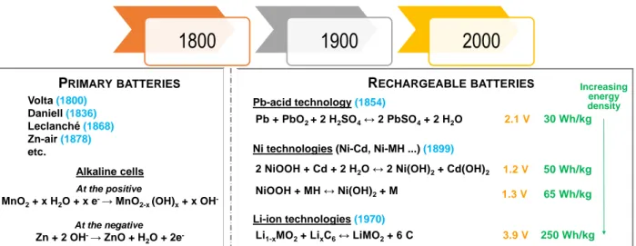
There are only a few battery technologies commercially relevant. From those dominating the market in terms of size and value (Li-ion, Pb/acid and alkaline Ni based either Ni/Cd or Ni/MH, see Fig. 1 for the reactions involved, their cell voltage and specific energy), all except Li-ion batteries are using aqueous electrolytes. This is related to their historical background, as all of them were developed at the end of the 19th century. Indeed, water was the most readily available solvent and almost the only one used before the widespread use of non-aqueous solvents began in the 1950s, in various fields of pure and applied chemistry. The use of organic solvent based electrolytes with a wider stability window enabled commercialization of the Li-ion technology with large cell potential (3-4 V) and thus higher energy density, despite some drawbacks associated to the need of building the cells in a moisture free environment. Yet, the interest in aqueous battery technologies has recently re-emerged, the main advantages of water-based electrolytes being their lower cost and non-flammability. Furthermore, due to very high ionic conductivities the water-based electrolytes are particularly attractive for high power density batteries.
Besides attempting to incrementally improve classical technologies (such as Pb/acid or Ni -MH), current research in the field of rechargeable aqueous electrolyte batteries focuses on two different approaches:
i) metal anode based, coupled to air cathodes for high energy density and
ii) metal-ion (M = Li, Na, Zn etc.) batteries mimicking their organic electrolyte counterparts.
The former has the intrinsic unsolved issues related to air electrodes, coupled to concerns related to dendritic growth, for instance, Zn metal anodes suffer from poor rechargeability, with performance limiting phenomena ascribed to mainly dendrite growth in alkaline environment. The most attractive figures would come for Li/air, but in this case protection of the Li anode to avoid H2 formation is mandatory, which adds cost and complexity (and safety risks) to the system. In contrast, the batteries based on metal-ion offer very interesting prospects and could challenge the hybrid supercapacitors [1,
3 2] delivering very attractive power densities combined with intermediate energy densities that could fulfil the requirements for grid applications.
Figure 1: Commercially relevant aqueous battery technologies, compared to the Li-ion batteries. The date
of the first published report on the main technologies are given between brackets in blue.
This review deals with the state-of-the-art research in metal-ion rechargeable battery technologies using aqueous electrolytes. Even if some mentions will be made in passing, no attempt will be done to cover primary chemistries or conventional nickel or lead based rechargeable technologies. Metal/air and redox flow concepts will not be discussed either. Different from the already existing reviews on aqueous electrolyte batteries [3-11], hereby, we keep the scope to univalent and multivalent cation chemistries namely Li/Na-ion and Zn-ion technologies providing in-depth description of their reaction mechanisms by probing different characterization tools as well as covering common technological challenging issues and perspectives to solve them.
In contrast to battery concepts in which the charge carrier ions are H+, Li+ or Na+, batteries based on multivalent metal-ions (i.e. Mg2+, Ca2+, Zn2+, Ni2+, Al3+, etc.) involve more than one electron transfer per ion. Table 1 shows the standard electrode potentials, ionic radii and theoretical capacities derived from metallic cation electrodeposition. From these values it can be deduced that only Ni (-0.257 V vs SHE) and Zn (-0.76 V vs SHE) metals can be used as metal electrodes in aqueous medium, as they fall within the water stability window. The voltage range associated to the decomposition of water is not an exact value as known from the Pourbaix diagram, instead, to be directly linked to the pH of the electrolyte 𝐸𝐻+/𝐻
2 = 𝐸
0 𝐻+/𝐻
2− 0.059𝑝𝐻 (see
Figure 2a). The standard reduction potential for the other metals is lower and falls outside the water
thermodynamic stability window. Thus, water reduction to H2 occurs before metal ions are plated (electrodeposited) on the negative electrode. Zn is the most electropositive metal that can be electrodeposited in water and it is a very attractive negative electrode, as it can exhibit high capacity (820 mAh g−1). These factors are most likely at the origin of recent renewed interest to develop Zn based rechargeable batteries.
1800
1900
2000
PRIMARY BATTERIES RECHARGEABLE BATTERIES
Pb-acid technology(1854)
Ni technologies (Ni-Cd, Ni-MH ...) (1899) Volta (1800) Daniell(1836) Leclanché(1868) Zn-air (1878) etc. Li-ion technologies(1970)
2 NiOOH + Cd + 2 H2O↔ 2 Ni(OH)2+ Cd(OH)2
Li1-xMO2+ LixC6↔ LiMO2+ 6 C NiOOH + MH↔ Ni(OH)2+ M Pb + PbO2 + 2 H2SO4↔ 2 PbSO4+ 2 H2O 30 Wh/kg 50 Wh/kg 65 Wh/kg 250 Wh/kg At the positive
MnO2+ x H2O + x e-→ MnO2-x (OH)x+ x OH
-At the negative Zn + 2 OH-→ ZnO + H 2O + 2e -Alkaline cells 3.9 V 2.1 V 1.2 V 1.3 V Increasing energy density
4
Table 1: Standard electrode potentials, ionic radii and theoretical capacities of different metal ions
2. Water as Electrolyte
Water is considered as universal solvent and can dissolve large concentrations of diverse ionic compounds. Its high dielectric constant and low viscosity (80 and 1cP respectively at 20°C) enable a very high ionic conductivity for aqueous electrolytes (i.e. ~ 1 S/cm in H2SO4 containing aqueous electrolyte), which is two orders of magnitude higher than that achieved with the organic electrolytes used in Li-ion batteries (~ 10-2 S/cm for LiPF6 dissolved in conventional carbonate based solvents) and hence aqueous technologies are appealing for high power density. Water solvates most of the salts straightforwardly due to the coexistence of Lewis basicity at the oxygen site and acidity at the hydrogen site. Then, desolvation enthalpy of Li+ ions is much lower in water when compared to organic electrolytes used in conventional Li-ion batteries (-34 kcal/mol in water vs -51 kcal/mol in propylene carbonate) [12]. In contrast, aqueous electrolytes are more corrosive than organic solutions and have a narrower thermal application range as their low temperature performance is limited by the freezing point.
The role of the electrolyte in batteries is less eye-catching but equally important as that of the electrode materials, as the energy separation between the lowest unoccupied molecular orbital (LUMO) and the highest occupied molecular orbital (HOMO) of its components determines the thermodynamic electrochemical stability window and hence the maximum potential attainable at cell level [13]. This window should be as wide as possible to enable compatibility with the strongly reducing/oxidizing electrode active materials and hence increase the energy density of the system. The theoretical thermodynamic electrochemical window of water is 1.23 V. This stability window is dependent on pH value (0.059 V per pH unit), as can be seen from the Pourbaix diagram given in Fig. 2. Despite this very limited thermodynamic voltage stability, in some practical cases the useful range can be extended due to degradation reactions being kinetically limited. For instance, it can attain 2 V for the Pb/acid technology due to the high overvoltage for the H2 evolution on Pb electrodes [14]. Indeed, water decomposition reactions (via electrolysis) involve an over potential at the surface of the electrode materials, water molecules’ adsorption/desorption at the surface of the electrodes induces local pH variations which shift the decomposition reactions at higher and/or at lower voltages. The water stability window can also be tuned/widened by the choice of the electrolyte salt and of its concentration (e.g. from more acidic LiNO3 and Li2SO4 to more basic LiOH).
Ions Voltage (vs SHE)
Ionic radii (Å)
Theoretical gravimetric capacity (mAh/g)
Theoretical volumetric capacity (mAh/cm3) Li+ -3.05 0.76 3829 2044 Na+ -2.71 1.02 1165 1128 Ca2+ -2.87 0.99 1337 2073 Mg2+ -2.36 0.66 2234 3882 Al3+ -1.66 0.53 2980 8046 Zn2+ -0.76 0.74 820 5854 Ni2+ -0.257 0.72 913 8133
5
Figure 2: (a) Potential vs pH stability diagram of water at 1 atm and 25°C. Below the equilibrium reaction
shown as a continuous blue line decomposition of H2O into H2 is favoured, while above the continuous orange line oxidation to produce O2 takes place. Main insertion materials studied as positive and negative electrodes in aqueous rechargeable lithium-ion, sodium-ion and zinc-ion batteries are given in (b), (c) and (d) respectively.
In the case of organic solvent electrolytes, such as those used in the Li-ion battery technology, the thermodynamic stability window is broader than 4 V [15, 16]. The degradation of the organic solvents results in the formation of insoluble products adhering to the electrode surface and forming a protective solid passivation layer. This layer is commonly known as solid electrolyte interphase (SEI) since it is ionically conducting and electronically insulating and its presence enables cell operation beyond the thermodynamic stability window of the organic solvent electrolyte. Thus, besides determining the practically accessible energy density, the electrolyte does also play a crucial role in the performance of the battery in terms of life
6 duration, as the stability of such passivation layers is crucial to avoid degradation. In aqueous batteries, since water decomposition products are either volatile gases (H2 or O2) or reactive ions (H+ or OH-) leading to the formation of water soluble products, such solid passivation layers do not form and hence uncontrolled oxygen/hydrogen evolution at the electrode surfaces takes place outside the stability window. Yet, there have been recent attempts to design aqueous highly concentrated electrolytes to prevent the presence of free water molecules in the electrolyte in which an SEI can be formed. This strategy will be discussed in details in section
6.1.
For an in-depth understanding of the reaction mechanisms involved in different parts of the battery (electrodes, solid-liquid interface between the electrodes and the electrolyte, current collectors, electrolyte, etc.), the involvement of a large panel of complementary characterization tools is needed, from the most widely spread in our laboratories to the most advanced ones [17]. Moreover, different length scales need to be probed from Å to nm for surfaces/interfaces to tenths of nm – m for electrode materials, to reach mm for full electrodes and full device [18], and due attention has to be paid to the sensitivity of the technique (surface vs. bulk) and also spatial and time resolution, which may enable mapping of dynamic processes. Different from the engrained energy storage mechanisms (i.e. insertion, conversion or alloying) in non-aqueous electrolyte batteries, additional side reactions might take places in water, which are deleterious to battery operation and may not be easy to detect. Indeed, as can be deduced from the Pourbaix diagram in Fig. 2a, shifting the potential of the positive electrode to higher voltage by decreasing the pH value of the electrolyte or to lower voltage at the negative electrode by increasing the pH value may result in generation of hydrogen or oxygen respectively at the opposite electrode. Other possible side reactions include: i) ion exchange between metal ions present in the solid and H+ present in the electrolyte, ii) partial dissolution of the active material within the acidic electrolyte, or else iii) H+ and/or H2O co-insertion together with the charge carrier ion (e.g. Na+) during the electrochemical process etc. The stability of the electrode materials varies with the pH value, it can thus be challenging to find a couple of positive and negative electrode materials, both stable at the same pH value to get a stable aqueous system. The presence of protons or water molecules within the structure can be detected combining Fourier transformed infra-red (FTIR) and solid state magic angle spinning nuclear magnetic resonance (MAS NMR) spectroscopies. Depending on the vibration frequencies observed in the FTIR absorption spectrum, the nature of the chemical bonds (atoms involved and their close environment) can be identified. MAS NMR gives additional information on the nature of the chemical bonds and on their electronic environment, as the shift of the NMR signal is characteristic of the spin transfer from the neighbouring paramagnetic transition metal ions towards the probed nucleus, which can be for instance 1H. Furthermore, a marked improvement in understanding the charge storage mechanisms has been obtained thanks to recent progress with electrogravimetric methods (electrochemical quartz crystal microbalance (EQCM) [19, 20].
Note that good performance at high rates demonstrates the power performance of the system but does not allow easy detection of side reactions (such as electrolyte decomposition) that depend on the residence time at extreme potentials and hence can more easily be observed at lower rates. Thus, testing in different conditions would be required to assess service life for the different concepts proposed. Since one of the suggested applications is ensuring power supply to data centers, research on the evolution of performance upon storing in different conditions is also mandatory.
7
3. Batteries Based on Univalent Ions
Aqueous rechargeable univalent alkaline batteries (based on transport of Li+ and Na+) have been recently revisited as very appealing alternatives to Li-ion batteries for applications requiring safe and low cost energy storage. The large panel of inorganic materials studied as positive and negative electrode materials for organic Li-ion batteries, and more recently for Na-ion batteries constitutes a rich database of materials to be considered “as a starting point” for aqueous alkali-ion batteries. (see Fig. 2a-c).
3.1. Aqueous Rechargeable Li-ion Batteries (ARLBs)
The first aqueous Li-ion battery was developed in 1994 [21], just three years after commercialization of organic electrolyte Li-ion batteries (LiB), using LiMn2O4 spinel (4.1V vs Li+/Li) at the positive electrode, VO2 (2.6V vs Li+/Li) at the negative electrode, and 5M LiNO3 + 0.001M LiOH in water as electrolyte. The addition of LiOH into the aqueous electrolyte induced an increase of the pH value to ~5 and allowed a slight shift of the potential and thus an increased stability of VO2(B) versus hydrogen evolution (Fig. 2b). It delivered an average voltage of 1.5 V, and was already shown at that time to be competitive with Pb-acid batteries. Nevertheless, the capacity retention was poor, lower than 50% after 100 cycles, especially at low rates, which was attributed to water oxidation and side reactions taking place concomitant to reduction/oxidation of LiMn2O4. [21]. The topic fell into oblivion as a result of progresses in the performance of organic electrolyte LIBs until a renewed interest for this eco-friendly electrochemical storage system appeared in the last few years [22] [23]. A few examples of the main ARLBs reported including materials and performance are given in Table 2 with the structures of the corresponding electrode materials being depicted in Fig. 3.
Table 2: The main examples of the full-cell aqueous Lithium-ion batteries, adapted from [5]
a Specific capacities are calculated with the weight of this electrode. b Capacity based on total electrodes including both the cathode and anode.
Cathode Anode Electrolyte Current rate
(C rate) Average voltage (V)
Capacity (mAh.g-1)
Retention (%) (no. of cycles) LiMn2O4 Activated carbon 1 M Li2SO4 0.2 A.g-1 1.25 26b 98 (20000)
LiMn2O4a Activated carbon 0.5 M Li2SO4 1.0 A.g-1 0.9 (vs NHE) 110 93 (10000)
g-MnO2a Activated carbon 1 M LiOH 0.1 A.g-1 1.0 34.7 83 (1500)
LiCoO2a Ni grid 0.5 M Li2SO4 1.0 A.g-1 0.9 (vs SHE) 130 96 (40)
LiNi1/3Mn1/3Co1/3O2a Activated carbon 0.5 M Li2SO4 12.8 A.g-1 0.6 (vs SCE) 90 90 (50)
Na1.16V3O8a Na1.16V3O8 4 M LiCl 5.0 A.g-1 0.7 (vs SCE) 150 80 (100)
LiMnPO4a LiTi2(PO4)3 5 M LiNO3 C/3 0.7 (vs SCE) 84 95 (50)
LiMn2O4 TiP2O7 5 M LiNO3 C/10 1.35 43b 35 (25)
LiMn2O4 LiTi2(PO4)3 1 M Li2SO4 10 mA.cm-2 1.5 40b 80 (200)
LiMn2O4 LixV2O5 5 M LiNO3 C/5 1.0 45b 78 (60)
LiFePO4a LiV3O8 9 M LiNO3 10C 0.3 (vs SCE) 90 99 (100)
LiCoO2a LiV3O8 satd LiNO3 1C 1.2 35 53 (100)
LiMn2O4a TiO2 3.5 M LiCl / 0.25 M Li2SO4 10C 1.9 130 90 (100)
LiMn2O4 VO2a 5 M LiNO3/ 0.001 M LiOH 0.01 A.g-1 1.1 63 72 (50)
LiMn2O4 Na2V6O16.0.14H2Oa satd Li2SO4 0.3 A.g-1 0.6 80 75 (200)
8
Figure 3: Crystal structures of the main inorganic insertion materials used as positive and negative
electrodes in aqueous rechargeable alkaline ion batteries.
3.1.1. The best positive electrode candidates of ARLBs
Compounds exhibiting high operation potential are obviously most attractive as positive electrode materials and most studies have been devoted to LiMn2O4, layered LiMO2 (M: Ni, Co or Mn) or LiFePO4, with the latter exhibiting a penalty in energy density derived from its lower operation potential. Following seminal work on LiMn2O4 discussed above, increasing the concentration of the electrolyte from 1M to 5M LiNO3 (pH ~ 5) appeared as a way to improve cycling performance, while at the same time inducing higher ionic conductivity and hence power capability. Indeed, increasing the pH can diminish the degree of H+ co-insertion with Li+ as well as Li+/H+ exchange. Interestingly, partial substitution of Mn by other cations was shown to also result in improved performance, which was attributed to the decreasing amount of the Mn3+ Jahn-Teller ions, mitigating the extent of the Mn2+ dissolution of the positive electrode material at the interface with the electrolyte through the disproportionation reaction 2Mn3+ Mn4+ + Mn2+sol. Despite the penalty in the energy density (lower amount of Mn3+ ions available to be oxidized), significant improvements in cycle life were achieved and 4000 cycles demonstrated for LiAl0.10Mn1.90O4 in 5M LiNO3 electrolyte at a cycling rate of 1000 mA/g (i.e. 9C) [24].
9 Co-intercalation of protons with Li+ is also an issue for layered oxides such as LiCoO2 and LiNi1/3Mn1/3Co1/3O2 [23]. H+ ions bond to oxygen from the crystal lattice forming OH- groups which hinder diffusion of Li+ ions from one octahedral site to another, as stabilized in the intermediate tetrahedral sites in the interslab space. Proton co-intercalation can be mitigated through the use of concentrated electrolytes and increasing the pH. The dissociation of LiNO3 (and other salts used in aqueous battery electrolytes such as LiOH and Li2SO4) is so high in water that very high concentrations can be reached without being detrimental to the electrolyte viscosity, and thus no issues arise related to the impregnation of the electrodes and to the kinetics of the intercalation and de-intercalation reactions, as is the case in organic Li-ion batteries. Note that increasing the salt concentration does also result in a decrease of freezing point of the electrolyte, and thus widen the practical temperature operation range,
In contrast, the co-intercalation of H+ is thermodynamically unfavorable in LiFePO4 as it would require severe distortion of all the coordination polyhedra FeO6 and PO4 [25]. Partial solubility of LiFePO4 is observed in basic electrolytes in the presence of oxygen, either present as traces or produced by water decomposition upon the operation of the battery, with the formation of Fe2O3 [Fe2+ + 2OH- + ¼ O2 ½ Fe2O3 + H2O] [26]. These side reactions can be reduced via carbon-coating which stabilizes the surface even in the presence of O2 and at pH 13.It was shown that by eliminating oxygen, adjusting the pH values of the electrolyte below 8 (Fig. 2), and using carbon-coatings, cells using LiFePO4 and LiTi2(PO4)3 (as positive and negative electrode materials respectively) exhibited excellent stability with a capacity retention over 90% after 1000 cycles at a rate of 6C, and of 85% after 50 cycles even at a low current rate (C/8) in 1 M Li2SO4 electrolyte [27].
3.1.2. The challenging negative electrodes of ARLBs
LiB negative electrode materials such as graphite or silicon cannot be used in ARLBs as they exhibit too low operation potentials to be stable within the water electrochemical stability window. Oxides and phosphates rich in vanadium or in titanium have thus been widely studied, as they are those exhibiting the lowest operation potential while being at the same time stable in water (Fig. 2 and Table 2). Unfortunately, all of them exhibit low ionic and electronic conductivity and thus induce a penalty in power performance. A problem of dissolution (i.e. corrosion) was identified for V5+O2, LiV5+3O8 and LiV4+,5+2O5. The use of coated electrode materials and of saturated electrolytes to reduce their content in free water molecules and oxygen, and thus their reactivity, were considered to solve such issues, as discussed above for LiFePO4. Nevertheless, maintaining the solvent free of oxygen all along the life of the battery is not obvious as some positive electrode materials (such as layered LiMO2) are metastable and can release oxygen during oxidation at high voltage, especially above room temperature. The stability of VO2 is also improved through coating with carbon [28] or even polypyrrole. [29] Alternatively, good electrochemical performances were obtained using H2V3O8 nanowires as electrode materials despite only 70% of capacity retention after 50 cycles at a current rate of ~C in 5M LiNO3 + 0.001M LiOH aqueous electrolyte [30]. H2V3O8 was shown to exhibit higher electronic conductivity than LiV3O8 due to the mixed valence state of vanadium (1V4+:2V5+) and also a better structural stability upon Li+ insertion and reinsertion thanks to the presence of H2O playing the role of pillars within the structure. However, the cycle life of cells using vanadium oxides as negative electrodes remains still limited. With respect to titanium containing phases, the pyrophosphate TiP2O7 and the NASICON phase LiTi2(PO4)3 have deserved most attention delivering initial capacities close to 100 mAh/g, the formation of a carbon coating being also compulsory for their chemical stabilization upon cycling [31].
10 Overall, the development of a suitable negative electrode material remains the main challenge in ARLBs, as none of the alternatives suggested to date are able to perform more than 100 cycles at a rate below 10C while retaining an acceptable capacity. To overcome this issue, activated carbon (typically used in supercapacitors) was proposed as a negative electrode (see Table 2) [32, 33] to build t hybrid electrochemical supercapacitors which exhibit high power rates to the expense of limited capacity.
As an alternative approach, aqueous solution of polysulfides (in the forms of K2Sx or Na2S5) were also proposed as negative electrodes for both aqueous electrolyte Liand Na-ion batteries with an average voltage being close to -0.5V vs SHE [S22- + 2H2O + 2e- ↔ 2HS- + 2OH-] [34, 35]. Since the electroactive material is dissolved in the electrolyte (so called anolyte), it needs to be separated from the positive electrodes, which makes the cell architecture somewhat different. Indeed, either Li-ion conductive glass membrane or ion-selective polymer membrane is needed to prevent migration of the polysulfides from the negative electrode to the positive electrode during the battery operation [36]. Proof of concept for this system was given using LiMn2O4, NaFePO4 or Na0.44MnO2 as positive electrode materials. It is worth to highlight that the redox mechanism for polysulfides in aqueous medium is different from the one taking place in organic electrolytes. While for the latter, a series of polysulfides Li2Sx (2<x<8) is formed that finally leads to insoluble and insulating Li2S, in aqueous systems three main types of chemical species are formed, H2S (aq), HS- and Sx 2-that are determined by the pH.
3.2. The Aqueous Rechargeable Na-ion Batteries (ARNBs)
3.2.1. The main positive electrodes of ARNBs
One of the first positive electrode materials proposed for rechargeable aqueous Na-ion batteries was Na0.44MnO2, exhibiting a tunnel crystal structure described in Fig. 3 [37], with the hybrid concept Na0.44MnO2 / 1M Na2SO4 aqueous electrolyte / Activated carbon (AC), being also developed and showing very good reversibility [38]. Interestingly, when Na0.44[Mn1-xTix]O2 is used as positive electrode using carbon coated NASICON NaTi2(PO4)3 as the negative electrode and 1M Na2SO4 aqueous electrolyte, a very attractive capacity of 76 mAh/g at an average voltage of 1.2 V and at a rate of 2 C is achieved [39] and Aquion Energy Ltd. released a commercially energy storage system based on this chemistry. According to the company, (bankrupted in March 2017) these 1.5V batteries could deliver 30 Wh.kg-1, with an efficiency of 85% after 5000 cycles, which is most likely still insufficient for some applications.
Systems using layered NaMnO2 as positive electrode material were also reported to exhibit excellent cycling behavior and high energy density both using activated carbon or carbon coated NaTi2(PO4)3 at the negative electrode. For the later, a 2M CH3COONa aqueous electrolyte was used and an energy density of 30 Wh.kg -1 (based on the total mass of active materials) was achieved with capacity retention of 75% after 500 cycles at a 5C rate [40]. Mn dissolution upon operation is a bottleneck for all Mn-based oxide electrode materials which, as already discussed, can be mitigated tailoring the electrolyte composition. Indeed, NaMnO2 was revealed to be stable upon long range cycling in the CH3COONa electrolyte, whereas rapid fading was observed in Na2SO4 (i.e. only 25% of the initial capacity was retained after 500 cycles) due to dissolution. Ionic transport in manganese oxides can be improved by tuning composition, coatings and particle morphology. For instance, the formation of a well ordered hydroxylated interphase at the surface of the layered Mn5O8 (or MnII2MnIV3O8) was shown to inhibit the oxygen evolution reactions at 3V.
11 More recently, a few polyanionic compounds have been also considered as positive electrode materials for ARNBs: Na2FeIIP2O7 [41, 42], Na3VIII2(PO4)3 [43], NaVIIIPO4F [44] and NaFeIIPO4 [45]. Amongst them, the olivine NaFePO4 prepared by chemical delithiation of carbon-coated LiFePO4has the highest theoretical capacity and operates at 2.9 V vs. Na+/Na, this value lying within the electrolyte stability window and allowing thus cycling at lower rates. Full cell batteries were built with NaTi2(PO4)3 as negative electrode, which delivered 0.6 V and 70 mAh/g.
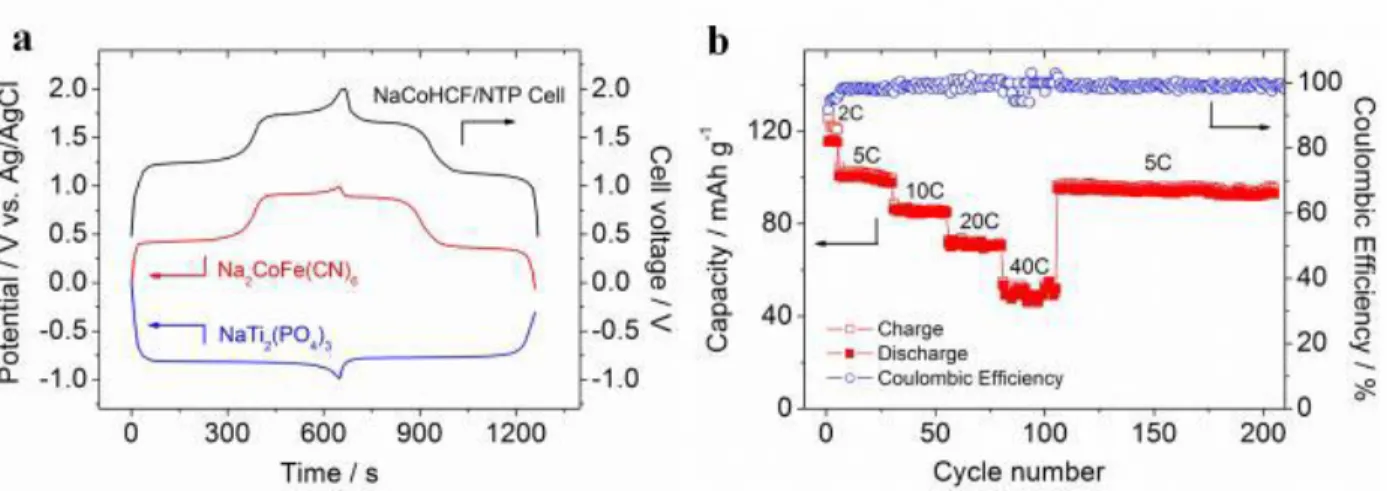
The Prussian Blue Analogues have also been tested as positive electrode materials for rechargeable aqueous Na-ion batteries, especially the copper, nickel and cobalt hexacyanoferrates (NaMHCF, for NaxMII[Fe(CN)6]y.zH2O with x ≤ 2, y ≤ 1, and M = Cu, Ni, Co). Their structures are similar to that of the ABX3 perovskite, a three-dimensional framework with large interstitial spaces for the alkali, and possible cation vacancies (y < 1) as well as inserted water molecules (z > 0). Full aqueous Na-ion batteries were built using the copper hexacyanoferrate at the positive electrode, NaTi2(PO4)3 as the negative electrode, and 1 M Na2SO4 aqueous electrolyte.These cells were shown to deliver a voltage of 1.4 V and a specific energy of 48 Wh/kg based on the total weight of the active electrode materials, which is higher than the one mentioned above for the concept developed by Aquion Technology. This system involves the redox couple FeII/FeIII and exhibits an high capacity and cyclability at high rate, with 88% of capacity retention over 1000 cycles at 10C [46]. That kind of chemistry is particularly interesting since the electrode materials and the electrolyte are abundant and low cost. Playing with the composition and the synthesis conditions allows to minimize the amount of FeII vacancies (or of MII vacancies, those MII ions being the redox centers) and to maximize the content in sodium in the structure, in order to optimize the reversible capacity. Improved performance was recently reported for nanosized Na2CoIIFeII(CN)6 as it was shown to be perfectly stoichiometric (i.e. with Na/MII = 1) (Fig. 4) [47]. When used in a full cell Na2CoFe(CN)6//NaTi2(PO4)3, appealing performances were confirmed with a high voltage of 1.7 V, a high energy density of 67 Wh/kg (based on the total weight of active materials) after 200 cycles. Interestingly, Natron Energy and Sharp from USA, Novasis-e from Canada and Altris from Sweden developed ARNBs based on Prussian Blue Analogues.
Figure 4: The electrochemical performances of the full cell Na2CoFe(CN)6//NaTi2(PO4)3. The cell was constructed such as it is positive-limited with a slight excess of negative electrode material. (a) The charge/discharge curves of the full cell (black line), of the cobalt hexacyanoferrate (NaCoHCF) (red line) and of the NASICON phase NaTi2(PO4)3 (blue line) (vs. Ag/AgCl) at a high rate of 5C. (b) Rate capability
12 and cycle performance of the full cell at various C rates, the capacity was calculated based on the positive electrode mass only [47].
3.2.2. The limited number of negative electrodes of ARNBs
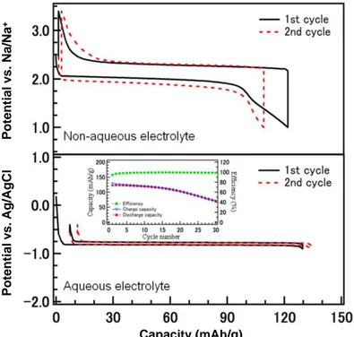
As highlighted in Fig. 2, mainly two V-based and Ti-based (Na2V5+6O16·nH2O and NaTi4+2(PO4)3 respectively) compounds exhibit suitable operation potentials to be considered as possible negative electrodes ifor ARNBs, with the latter having deserved most attention (Fig. 5) [48]. Similar strategies to those discussed above for ARLBs were applied to optimize NaTi2(PO4)3, involving the control of the particle size and morphology and the formation of a carbon coating. Nevertheless, despite significant improvements, the long range cycling performance is far from being optimized [49].
Figure 5: Electrochemical curves obtained at a rate of 2.0 mA/cm2 during the first and second cycles of a non-aqueous sodium cell NaTi2(PO4)3//Na (top) and of an aqueous cell NaTi2(PO4)3//Zn (bottom). The dependence of the capacity on the cycle number in the aqueous electrolyte is given in inset for NaTi2(PO4)3. The comparison of the two electrochemical curves reveal a drastic decrease of the polarization in aqueous electrolyte, the high ionic conductivity resulting in a low/negligible internal resistance [48].
Interestingly, a symmetric Na-ion battery was demonstrated; with the NASICON phase Na3MnIITiIV(PO4)3 at both the positive and negative electrodes. Its specific composition enables operation through two different redox couples Ti4+/Ti3+ and Mn3+/Mn2+ working on the negative side for the first and on the positive side for the second. This symmetric cell exhibits a voltage plateau centered at about 1.4V with a stable cycle performance and good rate capability. The energy density delivered by this aqueous system is about 40 Wh/kg (based on the total weight of the active electrode materials), which is comparable to or higher than
Capacity (mAh/g) P otential v s. Ag/ AgCl P otential v s. Na/Na +
13 the conventional aqueous rechargeable batteries and the recently developed aqueous sodium-ion batteries [50].
4. Batteries Based on Multivalent Ions
Two fundamental factors need to be taken into account when developing batteries enlisting ion intercalation reactions in aqueous electrolytes: i) the ionic radii and ii) the charge density of the ions. The ionic radius of the Zn2+ ion is 0.74 Å, which is very close to that of Li+ ions (0.76 Å) but its higher charge to radius ratio induces a much higher polarizing character which may limit its migration dynamics. Starting from Volta’s experiments in the early 1800s (Fig. 1), zinc has received great attention since it is the most electropositive metal that is relatively stable in aqueous media and has practical benefits (low cost, high abundance, environmental benignity and an already existing long tradition of Zn recycling).Zn-based batteries already exist at the marketplace as primary (single-use or non-rechargeable) alkaline Zn-MnO2 or Zn/air batteries. Alkaline Zn−MnO2 batteries exhibit a potential of 1.55 - 1.8 V, depending on the MnO2 polymorph used as positive electrode and on the electrolyte, and have become dominant in primary battery chemistry. The half-cell reaction occurring at the positive electrode is given below, it implies a H+ insertion in MnO2 in an alkaline solution with thus the partial reduction of Mn4+ in MnO2 to Mn3+ forming MnO2-x(OH)x.
MnO2 + xH2O + xe-→MnO2-x (OH)x + xOH-
Early indications of electrochemical activity of oxygen trace back to Van Marum (1801) and Leclanché, when they realized that their Zn/C-MnO2 batteries exhibited larger capacities when exposed to air. This observation led to the development of Zn/air primary batteries in the early 20th century, commercialized for the first time in 1932 and remaining the only commercially available primary metal-air batteries to date, with a theoretical energy density up to about 1.3 kWh/kg.
In contrast, the concept of Zinc-ion batteries (ZIBs) appeared somewhat later with the pioneering work published by Yamamoto [51] in 1986 demonstrating the possibility of using a mild aqueous electrolyte to minimize Zn dendrite formation and thus to build rechargeable systems. The topic has however received little attention for more than 2 decades. In 2012 Kang et al. demonstrated long cycle life (over 100 cycles) at relatively high current density (6C) for a rechargeable Zinc-ion battery using α‐MnO2 at the positive electrode together with zinc at the negative electrode and a mild ZnSO4 or Zn(NO3)2 aqueous electrolyte [52]. Afterwards, the numbers of publications on this subject increased steadily every year (Fig. 6a) [53]. The revival of this field has witnessed research focused on both the development of electrode materials and on the understanding of the reaction mechanisms and side reactions, the latter being at the origin of the loss of reversibility and performance.
Zinc ion chemistry in water is rather complex. Contrary to the binding of water molecules with alkali metal ions (Li+/Na+) via electrostatic interactions, Zn2+ ion builds much more covalent interaction with water molecules, which is in agreement with the high solvation energy for zinc ion: ~ 500 kcal/mole in aqueous solutions. Indeed, assuming six water molecules in the solvation shell of a central zinc ion (Fig. 6b) [54],
14 the enthalpy of solvation for one water molecule is ~ 80 kcal/mol, which corresponds to typical values for covalent Zn-O bond formation (70 to 85 kcal/mol) [55].
The redox reaction mechanisms for ZIBs are yet under debate, as besides the intercalation/de-intercalation of zinc ions, side reactions involving protons/water as those mentioned in the ARLBs and ARNBs are even more likely in this system, as a result of the lower mobility expected for divalent ions. These reactions can take place simultaneously to a greater or lesser extent depending on the experimental conditions (involving composition of electrodes/electrolyte but also battery operation related parameters such as current and potential).
Figure 6:
a) The number of publications up to August 2018 [53] b) Illustration of the bonding between Zn2+ and the first shell water molecules [54] c) Pourbaix diagram of Zn in aqueous solution from [56], d) a15
4.1. Negative Electrodes in Zn-ion Batteries
Herein, the imperative question is: what strategy could be used to promote rechargeability in the Zn based batteries after they have been used as primary alkaline Zn/MnO2 or Zn/air cells for a long time? As depicted in the Pourbaix diagram (Fig. 6c), in primary alkaline batteries there is precipitation of ZnO or Zn(OH)2 in electrolytes with pH values close to 13 [55-57] and the discharge product is the zincate ion (Zn(OH)42-) which ultimately precipitates as ZnO [57]. In basic solutions, the Zn anode exhibits various technical problems for rechargeability including: i) non-uniform Zn re-plating during the charge process with the formation of dendrites resulting in short-circuits of the cell, ii) high self-discharge related to Zn corrosion, and iii) limited power density. In neutral or mildly acidic electrolytes, high reversibility stripping/plating of Zn can be achieved according to the reaction [Zn ↔ Zn2+ + 2e-] (Fig. 6d). In more acidic electrolytes, severe corrosion of the Zn metal negative electrode occurs, and these should thus be avoided. As a consequence of these requirements, the most common salts used to prepare electrolytes with pH in the optimum range (4.0 to 6.0) are ZnSO4, Zn(NO3)2, Zn(CH3COO)2, Zn(ClO4)2, Zn(CF3SO3)2 or ZnCl2.
In general, the Zn metal negative electrode used in the aqueous rechargeable ZIBs is in the form of Zn metal foil, Zn powder or Zn paste, and dendritic metal growth is often observed upon electrodeposition. After continuous charging and discharging steps, small dendrite tips amplify via preferential deposition on the surfaces located especially at the edge of the electrode. Their growth rate is highly dependent on the current applied, and when large, they may penetrate the separator and result in the short circuit of the cells. The most effective methods to struggle against dendritic growth involve the use of different Zn electrode architectures, the protection by coating layers as well as the use of electrolyte additives. The architectures of the Zn electrode have been modified through the design of a sponge like three-dimensional porous monoliths to suppress dendrite formation [58] or of Zn/C composites with graphite, carbon nanotubes, activated carbons [59] to lower the charge transfer resistance and improve the reaction kinetics and electrochemical performances [60, 61]. Additionally, the coating of the Zn negative electrode with nano-CaCO3-coated has been shown to inhibit the dendritic growth [62]. Schematic illustrations of morphology evolution for bare and nano-CaCO3-coated Zn foils during Zn stripping/plating cycling is shown in Fig. 7. During the successive charge–discharge steps, dendrites/protrusions firstly nucleate on the small-sized nanopores of the nano-CaCO3-coating, grow (plating), and then are electrodissolved (stripping). Thus, the nano-CaCO3-coating results in a position-selected and bottom-up Zn deposition process at the interface between the metal foil and the coating layer, rather than a preferential deposition on the tips of Zn protrusions/dendrites. Similar effects can be observed using oxides (i.e. SiO2, AlO3 etc.). Despite rather similar galvanostatic electrochemical signatures (Fig. 7b), longer term stability is obtained with the nano-CaCO3-coated sample resulting in a 180 mAh/g discharge capacity over 1000 cycles while with bare Zn only delivers 120 mAh/g (Fig. 7c). Furthermore, in order to produce distinctively different crystallographic zinc orientation and surface textures, organic electrolyte additives such as sodium dodecyl sulfate, thiourea, polyethylene-glycol and cetyltrimethylammonium bromide have been used. These synthetic zinc electrodeposits were shown to exhibit 6 to 30 times lower corrosion when used as negative electrodes in aqueous rechargeable Zn-ion batteries [63]. In any case, such additives need to be tested in a full cell configuration to ensure their compatibility with the positive electrodes and not to inhibit the Zn2+ ion migration processes.
16
Figure 7: a) Schematic illustrations of morphology evolution for bare and nano-CaCO3-coated Zn foils during Zn stripping/plating cycling, b) Galvanostatic charge-discharge curves of the first cycle, and c) galvanostatic cycling performance of Zn|ZnSO4+MnSO4|CNT/ MnO2. Each battery used a CNT/MnO2 positive electrode, a glass fiber separator wetted with a 3 M ZnSO4 + 0.1 M MnSO4 aqueous electrolyte and a bare or nano-CaCO3-coated Zn negative electrode [62].
4.2. Positive Electrodes in Zn-ion Batteries
Besides manganese oxides (used in the primary concepts), the quest for ZIB positive electrode materials is, as in the case of ARLBs and ARNBs, also inspired on the existing knowledge developed for LiBs. Indeed, electrode materials which exhibit open structures able to reversibly insert/de-insert ions could, a priori, be employed also for multivalent ions (Fig. 2). These include Mn and V-based oxides, Prussian blue analogues and also Chevrel phases, organic (quinone-based for instance) or polyanionic (LiFePO4, Na3V2(PO4)2 etc.) compounds.
4.2.1. Mn-based oxides
MnO2 is characterized by a high theoretical capacity (~308 mAh/g for the exchange of 0.5 mol of Zn2+ per 1 mol of MnO2 and concomitant reduction of manganese to Mn2+) and can exhibit different polymorphs
17 (Fig. 8) [64] such as α-MnO2, β-MnO2, γ-MnO2, R-MnO2, δ-MnO2 or λ-MnO2, depending on the type of linkage (via edges and/or corners) between the octahedral unit [MnO6] in which Mn4+ is surrounded by six oxygen neighbours. Tunnel-type MnO2 polymorphs (i.e. α-MnO2, β-MnO2, γ-MnO2, R-MnO2) are arranged by corner sharing MnO6 octahedra with different tunnel sizes as depicted in Fig. 8a. The layered-type δ-MnO2 polymorph is formed by the stacking of slabs made of edge-sharing MnO6 octahedra, with the presence of water molecules or other cations to stabilize the framework. Depending on the nature of the inserted species, δ-MnO2 is called birnessite, buserite, chalcophanite or vernadite (Fig. 8b). The spinel-type λ-MnO2 polymorph is a, oxygen cubic-closed packed three dimensional framework with interlinked channels for diffusion (Fig. 8c).
Up to now, the redox mechanism was only studied in detail for the tunnel-type α-MnO2 polymorph, and its understanding still remains rather confusing with contradictory results being sometimes reported. Indeed, due to the complexity of the reactions involved, these contradictions probably come from the different conditions of study, in situ/operando or ex situ. Moreover, as well known for other electrode material chemistries and battery technologies, the control of the particle size and shape strongly influence the transport kinetics and thus significantly impacts the electrochemical performance of α-MnO2. The pH of the aqueous electrolyte which varies with the type of salts and their concentration is also expected to impact the electrochemical mechanism and the extent to which dissolution and reactions involving protons/water take place. Indeed, as depicted in the Pourbaix diagram of MnO2 (Fig. 8d) [65], between 0.0 and 1.2 V (vs saturated calomel electrode (SCE)) and at pH values below 7, solid MnO2 electrode is prone to dissolve generating Mn2+ species, while it is stable above 1.2 V. Thus, not only the electrolyte pH but also the cell’s cycling conditions (i.e. upper and lower cut-off voltages values, applied current etc.) play an important role. Moreover, after a series of reaction steps, the large stress can cause the gradual collapse of the tunnels or layers upon electrochemical cycling.
18
Figure 8: Polyhedral representation of the six Mn oxides reported herein: (a) Tunnel-like including α, γ, β
or R-MnO2, (b) layered-like -MnO2, (c) spinel-like λ- MnO2 [64] The MnO6 octahedra appears as violet or brown, whereas the sites available for insertion of ions are light grey octahedra or tetrahedral, (d) Pourbaix diagram of MnO2 [65]
The Zn2+ insertion/extraction reaction has been mostly studied for the α-MnO2 polymorph which has
relatively large tunnels with cross sections made of 2*2 MnO6 octahedra. The reactions taking place at the positive and negative electrodes are depicted below, the global process being: Zn + 2Mn4+O2 → ZnMn3+2O4.
Positive: 2 α-Mn4+O2 + Zn2+ + 2e- ↔ ZnMn3+2O4
Negative: Zn ↔ Zn2+ + 2e-
Zn-insertion into the host α-MnO2 structure and the formation of ZnMn3+2O4 were monitored by synchrotron XAS and ex situ XRD experiments, revealing the oxidation of Mn4+ into Mn3+ in agreement with a Zn/Mn ratio of 0.52 at the end of the discharge [66]. α-MnO2 nano-rods exhibited an initial discharge capacity of
β-MnO2(Pyrolusite) 1*1 cross section 2.3 × 2.3 Å2
Tunnel-like structure
α-MnO2(Hollandite)Spinel structure
2*2 cross section 4.6 × 4.6 Å2Layered-like structure
γ-MnO2(Nsutite) R-MnO2(Ramsdellite) 1*1 and 1*2 cross section
2.3 × 4.6 Å2 interlayer distance (~7 Å) -MnO2(Birnessite) λ-MnO2(Hausmannite)
a)
b)
c)
d)
1*1 and 1*2 cross section
2.3 × 4.6 Å2
Intergrowth between β-MnO2and R-MnO2
19 233 mA h/g at a current density of 83 mA/g with nearly 100% coulombic efficiency over 50 cycles. The formation of ZnMn2O4 is irreversible, as this phase exhibits large barriers for Zn migration.
H+/H3O+ intercalation/extraction: As in the case of primary alkaline cells, the MnOOH phase can be
formed upon reduction through the proton insertion into the lattice [Mn4+O2 + H+ + e− ↔ Mn3+OOH]. This reaction can be accompanied by significant morphological changes, for instance from micrometre-long nanofibers for α-MnO2 to short nanorods for MnOOH [67]. In this case, further investigation using Scanning/TEM and EDS mapping revealed that zinc was not inserted into the nanofibers but mainly distributed on the flake-like solid. Based on these findings, the authors postulated that during discharge, H+ from the electrolyte converts α-MnO2 to MnOOH, whereas OH− from the electrolyte reacts with ZnSO4 to form ZnSO4[Zn(OH)2]3. The overall reaction mechanism being:
Positive: H2O ↔ H+ + OH-
MnO2 + H+ + e- ↔ MnOOH
½ Zn2+ + OH- + 1/6 ZnSO4 + x/6 H2O ↔ 1/6 ZnSO4[Zn(OH)2]3·xH2O
Negative: ½ Zn ↔ ½ Zn2+ + 2e
-Overall: MnO2 + ½ Zn+ x/6 H2O + 1/6 ZnSO4 ↔ MnOOH + 1/6 ZnSO4[Zn(OH)2]3·xH2O
Phase transformations during operation can also occur. As highlighted for instance by transmission
electron microscopy (TEM) diffraction analysis, the tunneled α-MnO2 can be transformed into the layered δ-MnO2 (Zn-birnessite) during the discharge process involving also partial dissolution of manganese [68]. As discussed before, Zn2+ insertion into α-MnO2 is compensated by the reduction of Mn4+ into Mn3+, known as a Jahn–Teller ion due to its high-spin electronic configuration (d4=t2g3g1) and to be rather unstable. Indeed, Mn3+ ions easily undergo disproportionation into Mn4+ and water-soluble Mn2+ leading to the reaction: 2Mn3+ → Mn4+ (s) + Mn2+ (aq). This partial dissolution of Mn leads to cationic reorganization in order to stabilize the framework and thus to the transformation into a layered δ-MnO2 type structure. It was shown that Mn2+ ions dissolved in the electrolyte participate then, at least partially, in the electrochemical processes during subsequent oxidation. Indeed, Mn2+ ions are reversibly inserted back into the layers to reform the tunneled structure. This point has also been experimentally proven by replacing after the first discharge the electrolyte that contains dissolved Mn2+ ions with a fresh non-Mn2+ ion containing electrolyte: the cell was not able to charge supporting the hypothesis that the dissolution/deposition of Mn2+ ions takes an integral part in the redox reaction mechanism. Apparent contradictory results had been reported in the literature by the same research group [69], with in some cases the formation of the layered δ-MnO2 structure with co-insertion of two water molecules with Zn2+ ion in the interlayer (known as Zn buserite; a layered structure with a much larger interlayer distance (11 Å)) and in others only one water molecules (known as Zn birnessite, the interlayer distance is 7 Å). In fact, the first was transformed into the second by the loss of one water molecule during sample preparation (recovery, washing and drying) for ex situ characterizations.
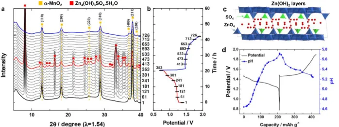
The increase in the Mn2+ ion concentration in the electrolyte during cell discharge is inherently accompanied by a rise in pH [MnO2 + 2 H2O → Mn2+ + 4 OH-] as observed with in-situ monitoring of the pH changes during battery operation (Fig. 9d), and it leads to the precipitation of zinc hydroxide sulfate Zn4(OH)6(SO4).5H2O on the positive electrode as:
3 MnO2 + 8 Zn2+ + 2SO42- + 16 H2O + 6 e- → 3 Mn2+ + 2 Zn4(OH)6(SO4)·5H2O ↓
As shown in Fig. 10, this phase disappears when the cell is charged to 1.9 V, in agreement with a precipitation – dissolution process taking place. The partial irreversibility of the Mn2+
dissolution/re-20 insertion being at the origin of the capacity fading, the use of MnSO4 as an additive in the electrolyte was proposed to mitigate this issue [67]. Indeed, the additional Mn2+ source in the electrolyte decreases the degree of manganese dissolution by shifting the MnO2(s)/Mn2+(aq) equilibrium and as a consequence prevents the formation of basic zinc sulfate on the electrode surface [53].
Figure 9: a) In situ XRD patterns recorded during Zn2+ insertion-de-insertion into/from -MnO2 in a zinc-based aqueous rechargeable cell with 1 M ZnSO4 aqueous electrolyte at a rate of C/20, b) the corresponding discharge–charge curve, c) Crystal structure of Zn4(OH)6SO4.5H2O, and d) pH variations during the first discharge–charge process [70].
4.2.2. V-based oxides
V-based materials (i.e. V4+O2, V4+S2, V4+,5+3O7·H2O, H2V4+,5+3O8 or Zn0.25V4+,5+2O5·nH2O) have also attracted attention for ZIBs due to the large panel of polymorphs that can be stabilized and to the different redox couples that can be involved, as vanadium is stable in different oxidation states V2+, V3+, V4+ and V5+. Up to now, the most promising results have been reported for V2O5·nH2O and Zn0.25V2O5·nH2O, the later exhibiting 220 mAh/g at a 15C rate, and a capacity retention > 80% after 1,000 cycles [71]. These two compounds are very similar and their crystal structure consists of vanadium pentoxide bilayers and water molecules in between, with also zinc ions in the case of Zn0.25V2O5·nH2O. (Fig. 10). The reaction mechanisms in ZIB are very similar to those already described for -MnO2: Zn2+ insertion as the main reaction and H+ insertion as well as formation of Zn4SO4(OH)6.4H2O as parasitic process. Co-insertion of Zn2+ and H2O has been proposed for V2O5·nH2O [72] and Zn0.25V2O5·nH2O [71] in which H2O molecules and/or ZnO6 octahedra would act as pillars and allow reversible expansions and shrinkages of the interlayer spacing to enable reversible Zn2+ intercalation and deintercalation. Likewise, the co-intercalation of water molecules would allow to screen the charges of Zn2+ ions and thus enhance the rate capability and capacity. The role of structural water was evidenced by solid state magic-angle-spinning (MAS) 1H NMR [72], water acting as a “lubricant” to promote fast Zn2+ transportation (Fig. 10).
-MnO2 Zn4(OH)3SO4.5H2O c d Zn(OH)2layers ZnO4 SO4
21
Figure 10: Scheme showing reversible water intercalation into Zn0.25V2O5·nH2O immersed in an aqueous
electrolyte: water intercalation would “induce” further Zn2+ intercalation concomitant to partial H2O deintercalation. The red and blue spheres represent O and H respectively; the H2O molecules interact with the oxygen layers through hydrogen bonding. Here y > z > n, those being the fractions of intercalated H2O molecules during cell discharge [71].
4.2.3. Prussian blue and its analogues
Prussian blue (PB) and Prussian blue analogues (PBAs) have also received great attention with redox activity being mostly associated with Zn2+ ion insertion. For copper hexacyanoferrate (C6Cu4FeN6) results of XPS analysis suggest that Zn2+ is inserted into the crystal structure and two low spin FeIII are converted simultaneously into low-spin FeII. The voltage of this battery system is as high as 1.73 V [73]. Despite their capacity not being very high (in most cases less than 70 mAh/g) these compounds seem to exhibit good cycling stability and power performance.
5. Challenges and Perspectives for Aqueous Electrolyte Batteries
Independent from whether the energy storage option is based on the di- or univalent systems, the use of an aqueous electrolyte results in some issues when compared to the LiB technology. The most relevant challenges to overcome are discussed below and schematically depicted in Fig. 11.
H2O Intercalation H2O intercalation H2O deintercalation Zn2+ deintercalation Zn2+ intercalation Zn0.25V2O5.yH2O in electrolyte Zn1.35V2O5.zH2O discharged Zn0.25V2O5.nH2O pristine
22
Figure 11. Main challenging issues of aqueous electrolyte batteries
5.1. Narrow Thermodynamic Voltage Window
As discussed above, typical aqueous Li(Na)-ion batteries are limited to low voltage (< 1.5V) and low energy density (<70 Wh/kg), often exhibiting limited coulombic efficiency especially at low cycling rates. This is attributed to the existence of parasitic reactions, mostly related to water decomposition at very high/very low potentials.
The limitations in terms of electrochemical potential window are currently being challenged through: (i) the use of highly concentrated electrolytes (“water in salt concept”) [74] and (ii) electrolyte additives. Moving to saturated aqueous electrolytes (12 M for Li2NO3 and 2.9 M for Li2SO4) was shown to enhance the coulombic efficiency of LiFePO4 in ARLBs, to achieve >80% capacity retention after 500 cycles at a 1.1C rate in a potential window of 0.8V [74] opening new research avenues to explore. Postmortem TEM analyses revealed no structural change in the bulk of the active material, but showed the formation of an amorphous surface layer which was found to be rather thick (up to 6 nm) for the most stable cells.
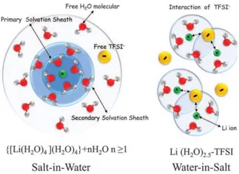
Since polarity of water molecules enables water to dissolve ionically bonded substances (i.e. salts), its positive part (the hydrogen atoms) attracting the anions and its negative part (the oxygen atom) interacting with the cations, a solvation (or in the case of water hydration) shell surrounds the both anions and cations (Li+, Na+ etc.), which has a significant difference when compared to organic electrolytes in which anions are almost unsolvated and hence cation transference numbers are very low. The thickness of the sheath can
C
HALLENGINGISSUES
Dissolved O2
Poor cycling Slow cation mobility
of MV-ions
S
TRATEGIESS
IDE/
PARASITIC REACTIONS M-ion/H+exchange Proton co-insertion H2O insertion Dissolution of electrode Phase transformation Artificial SEI Electrode coating Water-in-salt Electrolyte additives23 vary depending on the charge of the ion, its distribution and spatial dimensions. In the presence of a water in salt complex, (Fig. 12), the high salt concentration leads the anions (i.e. TFSI-) to enter in the (i.e. Li+) solvation sheath to compensate locally for the electrostatic field as there are not enough water molecules to do so. The close interaction between Li+ and TFSI- has been confirmed by Raman and 17O NMR spectroscopy. The benefits of using these electrolytes are two-fold: (i) no interaction of the water molecules with the electrode-electrolyte interface since they are too scarce, and (ii) interaction of the anions TFSI- with this interface leading to the formation of an SEI layer. According to thermal analyses the water-in-salt electrolytes are liquids at 25°C and can be cooled down to –90°C with a negligible crystallization of the salt, and its conductivity remaining ~10 mS/cm, comparable to that of a typical organic electrolytes (9.0 mS/cm).
Figure 12: Illustration of the changes in the Li+ primary solvation sheath in diluted (left) and water-in-salt (right) electrolytes. 4 or 2.5 water molecules are present in the primary solvation sheath of Li+, moving from the diluted (salt-in-water) to the highly concentrated (water-in-salt) electrolytes respectively [75].
More insights into the mechanisms involved were recently obtained combining especially FTIR, 1H, 7Li and 19F NMR and electrochemical experiments [76]. Indeed, these results clearly evidence that water reduction to form H2 does indeed take place in these systems (Fig. 13), with the formation of a fluorine-rich SEI as a result of a chemical reaction due to the hydroxide ions formed during reduction of water and reacting with TFSI anions. LiOH Precipitation /dissolution nucleophilic attack organic product Fluorinated SEI precipitation Li+ Li+
H
224
Figure 13: Scheme representing the formation of a stabilizing Fluorine-rich SEI at the surface of the
negative electrode [76]
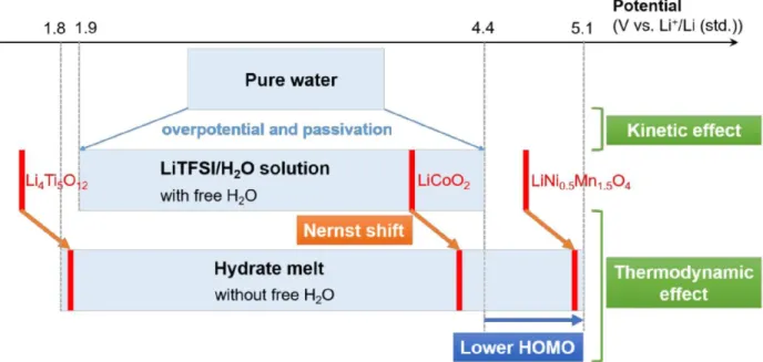
Aqueous electrolytes constituted by a mixture of lithium salts with different anions termed “hydrate melts” (e.g. Li(TFSI)0.7(BETI)0.3·2H2O) have also been reported to exhibit an extremely large potential window up to 3V (Fig. 14) enabling the assembly of 2.4 V LiCoO2/Li4Ti5O12 and 3.1V LiNi0.5Mn1.5O4/Li4Ti5O12 cells [77]. The use of two salts with very similar properties allow to overpass the solubility of LiTFSI in water and to decrease further the concentration in water. As an example, the hydrate melt made of the two organic Li salts (0.7 LiTFSI + 0.3 LiBETI) shows a minimized content in water (6.30 mol/kg only in a high concentration in salts 27.8 mol/kg). Playing with the chemistry of these melts it should be possible to tailor the composition of the SEI formed at the surface of the negative electrode and thus to stabilize - as proposed by Grimaud et al. [76] - these aqueous systems versus water reduction.
Figure 14: Electrochemical stability windows for pure water compared to concentrated LiTFSI in water.
Potential vs. pH stability diagram of water at 25°C. Below the “hydrate melts”. The operation potential of diverse conventional electrode materials for organic electrolyte Li-ion batteries are depicted in red [77]. It is also interesting to mention that combining the strategies mentioned above the layered oxide LiCoO2 was successfully stabilized at a high cut-off voltage enabling the reversible deintercalation and re-intercalation of 0.7 Li+ and thus to 170 mAh/g [74] using Mo6S8 at the negative electrode. The cells were shown to deliver a high energy density of 120 Wh/kg (per total weight of electrodes) during 1000 cycles performed at 2.5C and the capacity decay was limited to 0.013% per cycle. The key issue here appears to be the use of TMSB (tris(trimethylsilyl) borate) as an additive in the water-in-salt electrolyte (21M LiTFSI + 0.1 wt% TMSB), as XPS and TEM supported by first principles calculations demonstrated that TMSB is electrochemically oxidized forming a dense SEI on the surface of LiCoO2. This SEI contains mainly Si(OH)4 and B(OH)3 and helps preventing Co dissolution and other parasitic reactions at the electrode-electrolyte interface.
25
The “water-in-salt” concept was also recently spread into the field of ZIBs, with the use of high concentrated salt consisting of 1 M Zn(TFSI)2 + 20 M LiTFSI [78]. When high LiTFSI salt concentrations are used (≥ 20
M), Zn2+ is preferentially surrounded by TFSI− anions according to molecular dynamics and spectroscopic
studies. Stable (Zn–TFSI)+ species are formed, suppressing ZnO formation driven by the strong interaction
between Zn2+ and H
2O enabling long cycling stability over 4000 cycles without dendrite formation. Yet,
in light of the results reported for Li-ion systems [76], it is likely that water reduction is not suppressed in this system either, globally challenging viability of the approach.
5.2. Side Reactions Critical to Control
The presence of O2 in the electrolyte comes either from the hydrolysis of H2O, or arises from the fact that metal-ion batteries operate in air. This presence is highly detrimental to the cycling performance of the cells, since dissolved oxygen may chemically oxidize the electrode materials regardless of the pH of the electrolyte. For instance, LiFePO4 when operating in water reacts with O2 to form Fe2O3 and Li3PO4, leading to a fast capacity loss. To overcome this issue, the usual recipe is to coat the electrode material either with a thin layer of carbon or with a polymer, as well as bubbling N2 and Ar gases into the electrolyte prior to work.
Dissolution of active material has been shown to be a major problem causing capacity fading. This is
related to the composition of the electrolyte (with pH playing a very relevant role) and also to the composition of active material, with manganese being more prone to dissolution. Indeed, disproportionation of Mn3+ in manganese containing oxides to yield Mn4+ and Mn2+ which would dissolve in the electrolyte has been observed both in ARLBs and ZIBs. For the latter, results of elemental analysis indicate that the dissolution of Mn2+ ions stabilizes after the initial 10 cycles after having reached a certain concentration threshold. Therefore, pre-addition of a certain amount of Mn2+ ions to the electrolyte seems to be a means to overcome the issue.
The critical role of the current collectors: Auto dissociation products of water into OH− and H3O+ are highly reactive and can readily react with current collectors leading to corrosion. Likewise, electrolyte salts also play a crucial role. For instance, even though the conductivity of sulphate salts is lower than that of chlorides, zinc-ion battery studies in the literature mostly focus on ZnSO4 as the electrolyte salt since it is much less corrosive than chloride to stainless steel. As a whole, the choice of the current collector in the field of aqueous electrolytes is very important since all the cell components need to be both chemically and electrochemically stable. In the field of metal-ion battery systems, the current collectors are usually made of stainless steel, graphite, titanium mesh or nickel meshes, which have different resistances to corrosion, the pH of the electrolyte being the main factor determining the final choice. While stainless steel and nickel mesh cannot be used in acidic media, since they can react with the high concentration of H+ and have low corrosion potential at the basic media, usually, titanium meshes are suggested with high cycling stability. All these current collectors are expensive and heavier than aluminium (used in conventional non-aqueous Lithium-ion batteries), which is unfortunately prone to corrosion in aqueous media. Nevertheless, recent promising results have been obtained for ARLBs using a surface modified aluminium collector [79]. The formation of a chromium oxy-hydroxide monolayer as a coating was shown first to prevent the irreversible formation of Al(OH)3 at the interface between the aluminium foil and the electrolyte, and then to block the adsorption sites and the formation of the intermediate species at the origin of oxygen evolution [80, 81]. [81]. Replacing the current collector made of stainless steel by one made of aluminium modified by a coating allows pushing up the oxygen evolution peak of 2.7 V. As discussed in detail hereafter for hydrogen
![Table 2: The main examples of the full-cell aqueous Lithium-ion batteries, adapted from [5]](https://thumb-eu.123doks.com/thumbv2/123doknet/11557298.296820/8.918.114.813.673.902/table-main-examples-cell-aqueous-lithium-batteries-adapted.webp)
![Figure 6: a) The number of publications up to August 2018 [53] b) Illustration of the bonding between Zn 2+ and the first shell water molecules [54] c) Pourbaix diagram of Zn in aqueous solution from [56], d) a typical stripping and plating of Zn metal](https://thumb-eu.123doks.com/thumbv2/123doknet/11557298.296820/15.918.116.886.313.926/figure-publications-august-illustration-molecules-pourbaix-solution-stripping.webp)
![Figure 15: Exchange currents for electrolytic H 2 evolution versus metal–hydrogen bond strength for different elements [11]](https://thumb-eu.123doks.com/thumbv2/123doknet/11557298.296820/27.918.281.632.446.734/exchange-currents-electrolytic-evolution-hydrogen-strength-different-elements.webp)
