THÈSE
En vue de l’obtention du
DOCTORAT DE L’UNIVERSITÉ DE TOULOUSE
Délivré par l'Université Toulouse 3 - Paul Sabatier
Présentée et soutenue par
Ranine EL HAGE
Le 2 novembre 2020
Etude et optimisation d'une batterie à circulation tout vanadium
Ecole doctorale : MEGEP - Mécanique, Energétique, Génie civil, Procédés Spécialité : Génie des Procédés et de l'Environnement
Unité de recherche :
LGC - Laboratoire de Génie Chimique
Thèse dirigée par
Théo TZEDAKIS et Fabien CHAUVET
Jury
M. Carlos PONCE DE LEóN ALBARRáN, Rapporteur M. Vincent VIVIER, Rapporteur
Mme Béatrice BISCANS, Examinatrice M. Mathieu ETIENNE, Examinateur M. Théo TZEDAKIS, Directeur de thèse M. Fabien CHAUVET, Co-directeur de thèse
I am not the best person at expressing my feelings but I could not start this manuscript without thanking all the people who contributed directly or indirectly to this work, especially during the past three years spent at the Laboratoire de Génie Chimique, which I consider to be one of the greatest adventures in my life...
First of all, I would like to express my endless thanks to my supervisor Prof. Theo Tzedakis, who granted me the opportunity to explore the universe of electrochemistry and encouraged me to do better on a daily basis. His inspiration, motivation, insight and stimulation have helped me to achieve this work and I believe that in the past three and a half years most of his support was beyond his supervisory responsibility.
Also, I would like to thank my co-supervisor, Dr. Fabien Chauvet, with whom I had the pleasure to discuss experimental issues and interpret the different results. His continuous support, especially during the last months, was of great help.
In addition, countless thanks are dedicated to Dr. Fadia Najjar who provided me the opportunity to come to Toulouse for an internship and my adventure only grew from there.
I would like to acknowledge all the members of the jury who accepted to evaluate the present work: Dr. Carlos Ponce De Leon and Dr. Vincent Vivier for reading and commenting the manuscript and Dr. Mathieu Etienne and Prof. Béatrice Biscans for the examination and participation to the defense. Even though I would have preferred to meet all of you on the day of the defense, which was not possible due to the COVID-19 pandemic, it was still an honor to discuss with you over ZOOM.
Special thanks go to Prof. Biscans and Dr. Laurent Cassayre for their great input to the project and the numerous occasions on which we were able to exchange ideas and point of views for a better comprehension of the encountered problems. I would like to thank also Delphine and Waldemir, both post-doctorate candidates, who were a part of the team as well and contributed to the scientific and experimental progress of the project.
My deepest gratitude goes to the technical staff in the lab, Brigitte, Laure, Sandrine, Christelle and Vincent, for always being available for the smallest issues, as well as Pierre for the NMR analysis and Stéphane for preparing all the glassware I needed for my experiments.
As for all the researchers, the PhD and master students that I met throughout the years, I just want you to know that you made my life in the lab much more fun; thank you for all the good times, the laughs and the many activities we shared together. Charaf, Nabiil, Dihia, Chloé and Christophe, I will miss you all and good luck for your PhDs...enjoy it while it lasts. As for the girls closer to my heart, Chams, Fatma and Melissa, our “pauses café” and debatable “questions
Now outside the LGC, I would not even know where to start to thank each and every person who was there during the past three years, from the Lebanese community in Toulouse to “ةفدصلا ىدتنم” (Fatuta, Ranime, Sousou...), all of you made me feel at home away from home especially the “Chorale Maronite de Toulouse” (Charbel Y., Rouaida, Pierre, Mouin, Marie-Lou) to whom I owe most of my gratitude.
Special thanks go to my closer friends, Yolla, Georges, Ali, Mohammad/Marcel (aka. Houhou), Mcheik, Chams and Farah for all the memorable nights we spent together laughing and eating (the most sacred part of our gatherings!) and for being the most supportive people anyone could ever wish for in their life (yes you Yoyo, thank you brother). I could not forget to thank also my lifetime friends, Joelle, Eddy S., Elsi and Charbel Z. who have been there since longer than I can remember, you guys are the best...
I would like to thank from the bottom of my heart, the person who is the closest to this heart: Ali, thank you for believing in me when I did not believe in myself, thank you for the continuous support and thank you for tolerating and understanding me through the hard times.
Finally, I dedicate this thesis to my parents Gaby and Maha, without whom I would have never reached this far. I can never express how grateful I am towards them and my siblings Elie, Caline and Edy for their endless love and continuous motivation from the beginning.
i
Table of contents
...iGeneral introduction
...6Chapter I – Vanadium redox flow battery: Positioning and State of the art...10
Introduction...11
I.1. Energetic context and energy storage systems...11
I.2. Redox flow batteries...18
I.2.1. Definition and operating mode...18
I.2.2. Types of redox flow batteries and recent advances...20
I.2.3. Characteristic parameters for battery performance evaluation...23
I.3. All-vanadium redox flow batteries...24
I.3.1. Definition and characteristics of an all-vanadium battery...25
I.3.2. Battery components: advances and specifications...27
I.3.2.1. Electrode types and activation techniques...28
I.3.2.2. Electrolytic solutions...30
I.3.2.2.1. Solubility and stability studies for the negolyte...31
I.3.2.2.2. Solubility and stability studies for the posolyte...35
I.3.2.3. Additives for improving the stability of the electrolytes...40
I.3.2.4. Membrane and peripheral components...41
I.3.2.5. Vanadium solid-salt batteries...43
I.3.3. Functioning of the VRFB during cycling...43
I.4. Conclusion...44
References...46
Chapter II – Characterization and analysis of vanadium solutions...55
Introduction...56
II.1. Battery electrolytes preparation and experimental setups used...56
II.2. Experimental setup used for the electrochemical analysis of the vanadium electrolytes...58
II.3. Analytical techniques for electrolyte characterization...60
II.3.1. UV-VIS spectroscopy...60
II.3.1.1. Calibration of V(II), V(III) and V(IV)...62
II.3.1.2. Limitations of the technique...65
II.3.2. Potentiometric titration...66
II.3.2.1. Titration of V(V) with Fe(II)...66
II.3.2.2. Titration of V(II) and indirect titration of V(III) with I2...68
II.3.2.2.1. Potentiometric titration of the V(II) by iodine I3-...68
II.3.2.2.2. Indirect potentiometric titration of the V(III) by iodine I3-...69
II.3.2.3. Determination of the acid concentration...69
II.3.3. Inductively coupled plasma...73
ii
II.4.1. Apparatus used and calibration...76
II.4.2. Density measurements...79
II.4.3. Viscosity measurements...82
II.4.3.1. Apparent viscosity measurements of V(IV) solutions...82
II.4.3.2. Apparent viscosity measurements of V(V) solutions...83
II.4.3.3. Apparent viscosity measurements of V(IV) and V(III) suspensions...85
II.5. Conclusion...86
References...88
Chapter III – Elucidation of the effect of electrode material and solid particles on
the limiting current of vanadium using a three electrodes cell
...91Introduction...92
III.1. Characterization of the V(IV)/V(V) system (posolyte)...93
III.1.1. Effect of the electrode material on the oxidation current of V(IV) to V(V) in the absence or presence of KB particles...93
III.1.1.1 Graphite felt used as working electrode...93
III.1.1.1.1. Study of the blank solution...94
III.1.1.1.2. Study of the vanadium solution...97
III.1.1.2 Solid graphite used as working electrode...99
III.1.1.2.1 Effect of a graphite disc mounted on a rotating electrode body...99
III.1.1.2.2 Immobile graphite rod used as working electrode...107
III.1.2. Effect of the presence of vanadium solid particles (VOSO4) on the oxidation current of V(IV) to V(V)...109
III.1.2.1 Effect of solid particles studied on a GF and a GR electrode...109
III.1.2.2 Additional studies on the 4.5 M suspension...110
III.1.2.3 Study of the presence of Gum Arabic in the suspensions...113
III.1.3. Effect of the VOSO4 solid particles studied on a graphite cylinder rotating electrode...117
III.1.3.1. Characterization of the dissolved V(IV) oxidation current without solid...118
III.1.3.1.1. Effect of the stirring rate of the working electrode on the current – potential curves for the V(IV) oxidation without particles...118
III.1.3.1.2. Respective contributions of the disc and the cylinder faces of the working electrode on the V(IV) oxidation current...120
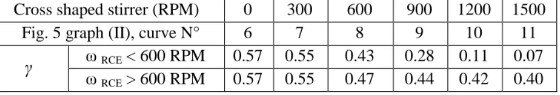
III.1.3.1.3. Effect of the coupled stirring rates of both the working electrode and the cross-shaped additional stirrer on the current – potential curves for the V(IV) oxidation...123
iii
III.1.3.2.3. Effect of the stirring of the L-VOSO4 suspension...130
III.1.3.2.4. Influence of Ketjen Black (KB) on the oxidation current...132
III.1.4. Study of the effect of concentrated V(V) solutions on the reduction current of V(V) to V(IV)...134
III.1.4.1. Preparation of V(V) concentrated solutions...134
III.1.4.2. Current – potential curves for V(V) solutions at 2.5 and 5 M...136
III.1.4.3. Effect of KB nanoparticles in concentrated V(V) solutions...138
III.1.4.4. Investigation on the existence of two species of V(V)...139
III.2. Electrochemical characterization of the V(II)/V(III) system (negolyte)...144
III.2.1. Preparation of V(III) powder...145
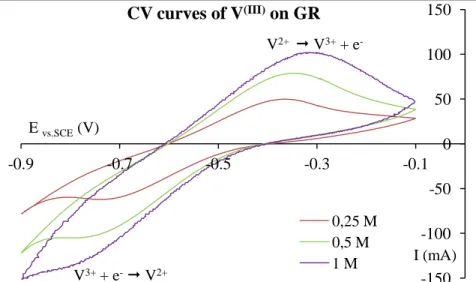
III.2.2. Study of the electrochemical behavior of the V(III) in solution or in suspension on a graphite rod...146
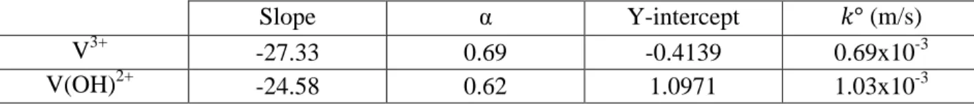
III.2.2.1. Effect of the V(III) and sulfuric acid concentrations...146
III.2.2.2. Effect of the presence of vanadium solid particles...151
III.3. Conclusion...152
References...155
Chapter IV – Kinetic study of the dissolution of vanadyl sulfate and vanadium
pentoxide in sulfuric acid aqueous solution
...158Introduction...159
IV.1. Material and methods...160
IV.1.1. Dissolution protocol...160
IV.1.2. Morphology and particle size distribution of the powders...160
IV.2. Dissolution of vanadium (IV) sulfate...161
IV.2.1. Characterization of the initial powder...161
IV.2.2. Temperature dependence of the dissolution kinetics...162
IV.2.3. Effect of stirring rate and particle size on dissolution kinetics...163
IV.2.4. Equilibrium data...164
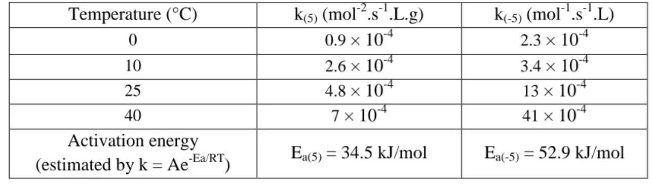
IV.2.5. Elucidation of the mechanism of the vanadyl sulfate dissolution...166
IV.3. Dissolution of vanadium pentoxide...170
IV.3.1. Characterization of the initial powder...170
IV.3.2. Effect of temperature on dissolution kinetics...171
IV.3.3. Effect of available surface area on dissolution kinetics...172
IV.3.4. Equilibrium data...174
IV.3.5. Kinetic model of the dissolution...176
IV.4. Conclusion...179
References...181
Chapter V – Influence of the presence of vanadium particles on the performance
of a filter press reactor under charge/discharge cycling
...183iv
V.1.1. Lab scale filter press electrochemical divided reactor...184
V.1.2. Apparatus used...187
V.1.3. Operating parameters and procedures...188
V.2. Charge-discharge cycles in homogeneous media (vanadium near to the saturation)...191
V.2.1. Preliminary charge-discharge cycle – electrolysis procedure description and optimization...191
V.2.1.1. Plot of the Current-overpotential (I=f(η)) curves for the initial system...192
V.2.1.2. Performing the electrolysis: half cycle ‘recharge’...193
V.2.1.3. Plot of the I=f(η) curves after that 50% of the required...196
V.2.1.4. Performing the electrolysis: half cycle ‘discharge’...197
V.2.2. Recharge-discharge cycling of the battery at C vanadium = 1.7 M...199
V.2.3. Effect of the presence of carbon black nanoparticles on the battery current...203
V.2.3.1. Preparation of the electrolyte: recharge of the battery until a conversion of 50 %...203
V.2.3.2. Performance of the battery during its discharge – Study of the improvement due to KB nanoparticles...207
V.3. Effect of the presence of solid particles on the performance of an all-vanadium redox flow battery...209
V.3.1. Study of a suspension containing an equivalent concentration of 2.5 M of vanadium...209
V.3.2. Study of a highly loaded suspension (equivalent concentration of 3.5 M of vanadium)...214
V.3.3. Cycling of the battery in the presence of solid particles: vanadium and KB...217
V.3.3.1. Equivalent vanadium concentration of 3.2 M...218
V.3.3.2. Equivalent vanadium concentration of 3.2 M in presence of KB...221
V.4. Interpretation of the results and comparison between the electrolyses...223
V.5. Establishment of theoretical mass balance models for an operating vanadium solid-liquid redox flow battery...230
V.5.1. Mass balance established during the recharge of the battery (galvanostatic mode)...234
V.5.2. Theoretical mass balance established for the discharge of the battery (galvanostatic mode)...242
V.6. Conclusion...247
References...250
General conclusion and perspectives
...253Nomenclature
...2596
General introduction
The continuous development of industries and the global population growth are increasing the energy consumption worldwide, thus increasing the demand for fossil fuels, which constitutes the main energy source for its high energy density and ease of handling. However, the instability of the fuel prices on one hand and the greenhouse gas emissions and the substantial environmental impact of fuel consumption on the other hand, led to look for alternatives and invest in the renewable energy sources such as solar, wind, water…
Exploiting renewable energy sources requires developing corresponding storage devices, because of their intermittent nature; thus it is essential to conceive energy storage systems suitable for the grid needs and able to balance between supply and demand of energy.
The types of energy storage systems (ESS) are numerous and expand on a wide range of capacity, power density and capital costs. Some of them are dependent on the geographic localization (hydropower, compressed air, wind) and others are very costly (flywheels, 1500 and 6000 $/kWh) or still dependant on raw material from fossil fuels (hydrogen fuel cells). The electrochemical storage in redox flow batteries (RFBs) came as a solution of choice because it resolved the problems of geo-localization and fossil fuels dependency and the cost was significantly reduced to 180 - 250 $/kWh (depending on the redox couples and material used). In addition, they introduced the advantages of independent sizing of the power and energy and the possibility of operating at room temperature. However, compared to the previously cited ESS, their power rating is still low: between 0.5 and 100 MW compared to the size of the pumped hydro energy storage, for example, in the range of 1000 – 3000 MW. The RFBs types can be divided mainly into two categories, the organic and the aqueous systems. The first ones allow achieving cell voltages greater than 3 V but they are compromised by the difficulty to achieve high energy densities due to the low solubility of the electroactive species in non aqueous media. In return, the aqueous RFBs involve generally soluble metal ions but the cell voltage is less than 2 V in general.
One of the major drawbacks of the RFBs, constituted by two “very different” electroactives species (two separate redox couples), is the cross-contamination problems between the two compartments which i) decreases the energy efficiency of the battery and ii) largely increases the recycling costs of the system.
The redox battery of interest in this work is the all-vanadium redox flow battery (VRFB) which was the only system that could reduce the cost of the cross-contamination, since the only element used for the electrolyte solutions is the vanadium in its four oxidation states. In this case, the cross-contamination is simply a fraction of electricity loss, and a periodic need to re-equilibrate the volume of the electrolytes. Nevertheless, because of the relatively high weight of the vanadium, the VRFB suffers from a low energy density (~ 40 Wh.kg-1 compared to ~ 150 Wh.kg
-7
1
for Li-ion stationary batteries) in addition to the relatively low solubility (< 2 mol.L-1) of the vanadium salts in sulfuric acid and in a limited temperature range (10 to 40 °C).
An objective of this thesis is to define the formulation of the electrolytes in order to increase the stored energy density by using vanadium suspensions as electrolytes, i.e. excess solid particles in a saturated solution. The study consists first in preparing, analyzing and characterizing the electrolytes (posolyte V(IV)/V(V) and negolyte V(II)/V(III) ), thus expecting to find their optimal composition. Therefore, it is essential to understand the physico-chemical phenomena occurring during the charge-discharge cycling and thus determining the unexpected problems and establishing laws governing these processes to overcome any eventual limitation.
The presence of vanadium solid particles will be studied in order to examine how to manage the mixed suspensions (presence of both the dissolved and liquid forms) and their effect on the stored energy density. On the other hand, being inspired by their use in Li batteries as electric conductor, carbon nanoparticles are also involved; their interactions with both the current collector (electronic percolation) and the vanadium particles are analyzed as well as the corresponding effects on power and capacity of the battery.
Therefore, it was essential to carry out several preliminary studies to get the required knowledge of the system and the laws controlling it, before conceiving and elaborating a VRFB (at the laboratory scale). The idea is to reduce as much as possible the stored volume and simultaneously to increase the energy density stored. Note that the optimization of the power density of the reactor is also an objective of the thesis which implies the design of an efficient electrochemical reactor with continuous flow.
Mass and charge balances are performed for charge/discharge cycles, expecting i) to establish correlations that link the response of the system (current, voltage, energy and reversibility) to the (influencing) operating parameters, and ii) to compare the various yields (voltage, energy, faradic) between the cycles of the battery.
In order to achieve these objectives, this manuscript is structured in five parts. In the first chapter, an overview of the existing energy storage systems is presented with a focus on redox flow batteries. The working principle of the RFBs along with the different types and their limitations are presented leading to the introduction of the all-vanadium redox flow battery. The components of the VRFB are introduced (electrodes, membrane, additives…) while the existing studies of the electrolyte characteristics (solubility, density, viscosity) are developed in order to have a complete vision of the factors inducing the low energy density of this system.
The second section is devoted to the methods used for the characterization and analysis of the vanadium electrolytes, which can be divided into three categories. First, the tools used for the electrochemical preparation of the vanadium salts/solutions and the setup for the electrochemical
8
analysis in a half-cell configuration (three electrodes cell) are presented. Then, in order to be able to have a quantitative follow-up of the four oxidation states, analytical techniques are examined and we have defined the appropriated methods for the corresponding species of the vanadium: UV-Vis spectrometry and potentiometric titration. Finally, for the analysis of the physico-chemical properties of vanadium solutions and suspensions, experimental setups are conceived, elaborated and calibrated to measure the density and apparent viscosity of the studied electrolytes.
The electrochemical analysis in the three electrodes cell of the vanadium electrolytes is undertaken in chapter III, expecting to understand the effect of several parameters on the resulting limiting current, aiming to extrapolate the results on the reactor/VRFB. The studied parameters include the electrode material (graphite felt and solid graphite), the vanadium oxidation states (V(III), V(IV) and V(V)), the concentration of the active species and the presence of solid particles (vanadium salts and/or Ketjen Black).
In chapter IV the dissolution kinetics of two vanadium species (vanadyl sulfate VOSO4 and
vanadium pentoxide V2O5) are addressed. The aim is to get a better understanding of their
dissolution mechanisms. The general purpose will then be to establish, through simple models, the corresponding kinetic laws; these laws will be used to calculate the dissolution rate and to describe the temporal evolution of the vanadium concentrations.
The last chapter of this thesis is dedicated to the conception, design and study of a VRFB based on a filter press reactor connected to two external storage tanks. The system operates with vanadium suspensions as electrolytes and the aim is to evaluate the enhancement of the energy density of the battery compared to the ‘all liquid’ VRFB. Recharge-discharge cycles are undertaken and the cell voltage, the electrodes overpotentials and the vanadium concentrations are monitored. Moreover mass balances for the various species at the macroscopic scale established and solved, and the corresponding results are compared with the experiments.
The study presented in this manuscript is closed with a general conclusion along with the required points remaining to consider finalizing the project (indicated as perspectives).
10
Chapter I – Vanadium redox flow battery: Positioning and State of the
art
Table of contents:
Introduction
I.1. Energetic context and energy storage systems I.2. Redox flow batteries
I.2.1. Definition and operating mode
I.2.2. Types of redox flow batteries and recent advances
I.2.3. Characteristic parameters for battery performance evaluation
I.3. All-vanadium redox flow batteries
I.3.1. Definition and characteristics of an all-vanadium battery I.3.2. Battery components: advances and specifications
I.3.2.1. Electrode types and activation techniques I.3.2.2. Electrolytic solutions
I.3.2.2.1. Solubility and stability studies for the negolyte I.3.2.2.2. Solubility and stability studies for the posolyte I.3.2.3. Additives for improving the stability of the electrolytes I.3.2.4. Membrane and peripheral components
I.3.2.5. Vanadium solid-salt batteries I.3.3. Functioning of the VRFB during cycling
I.4. Conclusion References
11
Introduction
The production of energy has received considerable development in the recent years due to massive industrialization and technology developments. Fossil fuels and petroleum products were and still are very popular because of their high energy density, their ease of handling and their relatively easy storage and transport. However, when burned, carbon dioxide (CO2) is
formed in majority, and as function of the system various other gases (carbon monoxide (CO), nitrogen oxides (NOx), sulfur oxides (SOx), volatile organic compounds (VOCs)) most often having a certain toxicity are produced. Moreover, particulate matter are emitted, having noticeable impact on health and environment and leading to global warming. Thus, a global campaign to search for effective and clean alternative fuels and energy storage systems started; it expects to expand the energy from different “natural” processes, mainly wind, hydropower and solar sources which became the focus of many governments, and encouraged research teams to take that path. Most of the sources of energy were widely studied, and optimized systems are currently operational; however, a need to find suitable storage systems that are cost effective and reliable at the grid scale is essential. The intermittency of the renewable energy sources adds a challenge to their storage in particular for non-stationary applications, where autonomy is needed (electric vehicles, computers, cell phones…).
Various methods were proposed for the energy storage for stationary systems: mechanical systems, water reservoirs (hydropower-dams), air compression systems, flywheels, chemical and thermal systems, hydrogen storage systems and electrochemistry (batteries, fuel cells). Until now, except the water reservoirs no other system can be considered as cost effective for large storage applications.
In this chapter, the different modes of stationary energy storage systems (ESS) will be developed briefly with their specifications and drawbacks. The main focus will be on the electrochemical storage through all-vanadium redox flow batteries (VRFB) which are the aim of this project. The different components of the VRFB will be developed with a focus on the characteristics of the electrolyte solutions and the problems encountered, facing the commercialization of the battery.
I.1. Energetic context and energy storage systems
Nowadays around the world, the energy is stored mainly by pumped hydro energy storage (PHES) that accounts for 140 GW of the centralized energy, followed by 400 MW stored through compressed air and wind turbines, 300 MW in sodium–sulfur batteries, 270 MW in lithium–ion batteries and 100 MW in lead batteries [1]; this energy stored accounts for only 1/130 of the worldwide energy consumption which was 18 TW in 2019 [2]. The electrochemical storage of energy with different kinds of batteries has increased in interest in the last decade,
12
mainly because they are easier to handle and more susceptible to be used for non-stationary applications, and large scale energy grids can be achieved through redox flow batteries.
The selection of an appropriate energy storage system (ESS) for energies from renewable sources depends on a number of factors such as storage investment costs and electrical power, cycling life, energy efficiency, temperature, humidity and salinity conditions and most importantly security and environment [3]. Numerous techniques have been introduced in the past few decades and are based mainly on hydropower, air compression and electrochemical conversion.
Hydropower or pumped hydro energy storage (PHES) had a peak evolution in the 1970s, after the oil crisis and most of the plants were build between the 1960s and the late 1980s [4-5]. The fundamental principle of PHES is hydraulic potential energy: at times of low demand, the electricity serves to pump water from a lower reservoir to a higher reservoir. Recovering the electricity during periods of high demand is done by powering a turbine through the descent of water by gravity from the higher to the lower reservoir. The efficiency of this storage system can reach between 70 and 80 % with a typical rating between 1000 and 3000 MW [6]. The limitations of this ESS are the water availability, a favorable geographical location and topography (high surfaces), satisfactory geotechnical conditions and access to electricity transmission networks. The power capital cost of the PHES is estimated to be between 2000 and 4300 $/kWh and the energy capital cost between 5 and 100 $/kWh [4].
Another storage system is compressed air energy storage (CAES), introduced in the 1940s but was not truly developed until the 1970s. The basic concept of the CAES system is that the electricity powers a compressor that converts the electric energy into potential energy of pressurized air, stored typically in underground caverns. The release of this air by expansion through an air turbine regenerates the electricity stored, according to demand [7-8]. However, the limited success of CAES comes from several economical and technical aspects such as lower cycle efficiencies than PHES or batteries, geological restrictions and efficiency losses due to dissipation of thermal energy during compression and expansion. Hybrid techniques between CAES and PHES have been considered using a micro-pump turbine (MPT) [5] including two tanks, one open to the air and the other subjected to compressed air. The MPT uses the exceeding power from the grid to pump the water, which compresses the air, to be stored. In the recovery process, the energy in the air is released to drive water through the MPT to generate power. PHES and CAES are considered to have large power and storage capacities compared to other storage systems, but as mentioned before, they are limited by the geology and the availability of water and empty underground caverns and this contributes in the increase of the power capital costs to a range between 400 and 800 $/kW [6].
13
Energy can also be stored in the form of kinetic energy using flywheels (FW) [9], which is considered to be one of the oldest mechanical ESS; for example, they were used on trains and steam engine boats and as energy accumulators in factories during the 18th century. It is only in recent years that the improvements in materials, magnetic bearings, power electronics, and the introduction of high speed electric machines that allowed the introduction of the FW as a valid option for energy storage applications [10]. The energy in flywheels is stored in the form of rotational kinetic energy of a spinning mass, where a rotational disk connected to an electric machine speeds up for storing the energy and slows down for its regeneration as required [9-10]. The advantages of the FW such as low maintenance, fast response time, high energy efficiency and eco-friendly features are confronted with costly cryogenic cooling devices which increases the total cost of the FW and reduces the overall energy efficiency, in addition to containment problems, high friction and gyroscopic effects from the Earth’s rotation. The installation costs of FW are also high, between 1500 and 6000 $/kWh [11], with power costs of 250-350 $/kW [6]. The fourth most important energy storage system is the thermal storage, first investigated in the 1970’s after the energy shortage crisis [12], and it is divided to three main categories: sensible heat, phase change and chemical reaction. By using sensible heat technique, thermal energy is stored by raising the temperature of a liquid or a solid, and depends on the specific heat of the material, the temperature increase and the amount of available material. Aquifer systems, rock beds and ground and soil systems are among the most used structures for the sensible heat energy storage. For the phase change (or latent heat), as the name suggests, it is based on the phase change of a material with temperature, thus absorbing or releasing heat in the form of latent heat in isothermal conditions. Organic, inorganic or eutectic substances (phase change materials or PCM) are used for their thermal, physical, chemical, kinetic and economic properties and are chosen as a function of the application of the latent heat technology [13]. Lastly, thermal storage by chemical reaction relies upon a reversible reaction between two substances A and B (A + B C + heat), with an exothermic synthesis and an endothermic decomposition process. The reaction can also occur by sorption processes (adsorption or absorption) depending on the material used. Chemical storage has some advantages, such as low heat losses, capability to conserve energy at ambient temperature as long as desired because the reagents A and B can be stored, after separation, for a long period, and finally, as function of the reaction, a high energy density can be stored. However, the studies on the chemical storage are still in their early stages and are not yet as developed as the phase change or the sensible heat techniques. The capital cost, calculated on a power density base, for thermal energy storage is 200 to 300 $/kW and 3 to 60 $/kWh for energy based calculations [14].
The numerous advantages provided by the thermal storage systems, such as reliability (sensible heat), providing thermal energy at constant temperature (phase change) and negligible heat loss (thermochemical), are confronted with the high cost of these techniques, the low energy density of the sensible heat, the corrosion that results from the latent heat processes and the uncertain
14
stability of the chemical reaction technique and many other setbacks that limit the applicability of these ESS.
The superconducting magnetic energy storage (SMES) is another ESS based on the creation of a magnetic field in an induction-coil, using electricity [15]; a superconductor with no resistive losses operates at a cryogenic temperature and produces a magnetic field. The energy produced remains constant and is stored until required usage. However, the energy density of the SMES is limited by mechanical considerations to a rather low value of around 10 kJ.kg-1 [16]; the coil and the magnet must be strong enough to withstand the large magnetic forces when energized, but its power density can be extremely high with a cost of 150 to 250 $/kW [17]. Therefore, SMES are interesting for high-power and short-time applications but not applicable for large grid storage systems.
All the previously mentioned EES have their specific features, with their respective pros and cons, making each one suitable for their aimed applications: PHES, CAES and thermal energy storage correspond to long-time scale (hours) storage while flywheels and SMES have a fast response time (s-min time scale) but are considered as expensive systems.
Lastly, the storage techniques that are mostly spread are the ones using electrochemistry and they are classified according to their operating mode:
- quasi-reversible conversion of electrical to chemical/physical energy and the corresponding reverse process (batteries and super-capacitors);
- conversion of the electrical energy to chemical energy (electrolysers for the production of electroactive materials);
- conversion of the chemical energy to electricity (fuel cells).
Electrochemical energy storage strongly expanded in the last few decades, and important efforts were spent to optimize the techniques mentioned above. All of these techniques are presented in the simplified Ragone diagrams (Fig.I.1), which show comparatively the power and the energy of each system. In fact, power and energy are the two universal parameters that allow comparing all ESS. Capacitors, for example, have a specific power similar and even higher than combustion engines (based on fossil fuels) but their power is at least 104 times lower. The application range of capacitors is limited to backup circuits of microcomputers, smoothing circuits of power supplies and timer circuits that make use of the periods to charge or discharge electricity [18] because of the law quantity of energy that they can store despite their high specific power.
15
Fig.I.1: Left: Simplified Ragone diagram of the energy storage domain for electrochemical energy conversion systems compared to an internal combustion engine [adapted from 19]; Right: focus on the different battery types.
The electrolytic capacitors or super-capacitors or electric double-layer capacitor are considered as second generation capacitors; the electric energy is stored in an electrochemical double layer formed at a solid-electrolyte interface [20]. The capacitance can be increased by increasing the effective internal surface of the electrodes by using porous electrodes while various electrolyte – electrode couples were studied for improving the performances. Super-capacitors are considered to be safe devices, do not require cooling systems, are environmentally friendly and have high cycle-life. However, they are restricted to low energy applications, otherwise, it would require several cells. Also, they must become cost competitive in comparison with batteries since they cost 100 to 300 $/kW (or 300 to 2000 $/kWh) [14].
Before addressing batteries, one ESS remains: fuel cells, with the mostly known system, the hydrogen storage. The fuel cells are systems that produce electricity and heat as long as fuel is supplied. Different types of fuel cells exist nowadays such as polymer electrolyte membrane (PEM) fuel cells, direct-methanol fuel cell (DMFC), alkaline fuel cells and solid oxide fuel cells and they differ by the type of electrolyte employed. In fact, the fuel cells are formed by two electrodes separated by an electrolyte. Their operating mode can be described by the following: the hydrogen, stored in liquid, solid or gaseous forms, enters the fuel cell at the anode where it is split into protons, then the protons are transported to the cathode where they react with oxygen to form water and release heat [21]; thus, the principle of a fuel cell is not based on combustion but on an electrochemical reaction. Therefore, the direct production of electricity from hydrogen without the generation of undesirable waste products puts the fuel cells as a suitable candidate for stationary and non-stationary applications. Nonetheless, these systems are confronted with many disadvantages such as the production and source of hydrogen: 95 % of H2 production is
from fossil fuels reforming [22]; this not only generates CO2 but also can be the source of
impurities (CO residues, NOx, H2S…) in the fuel cells. These contaminants affect the
performances of the cell by poisoning the electrode catalysts, reducing the conductivity and the mass transfer [23]. It is worth mentioning as well the high costs relative to a fuel cell system
16
from the membrane and the electrode materials usually noble metals. The average capital cost of a hydrogen fuel cell can go from 500 to 10 000 $/kW [14] depending on the material used. Last but not least, the most commonly used form of energy storage, especially for mobile applications, are the batteries. A wide diversity of batteries (secondary batteries, i.e. rechargeable batteries) exists and some of them are presented in Fig.I.1; they are differentiated mainly by the nature of their electrolytes (aqueous or organic) and their operating temperature. The batteries are based on electrochemical reactions occurring for the charge and discharge: during the charge, the electricity provides the required energy to the system to perform the non-spontaneous reactions and during the discharge the opposite spontaneous reactions take place to regenerate the stored energy. The batteries could also be classified as function of the method employed for storing the electroactive elements [24]:
- inside the battery for stationary used systems (Pb-acid batteries, alkaline, Li,…);
- outside the battery with flowing electrolytic solutions containing redox active species through the battery (redox flow).
The first rechargeable batteries, introduced in 1859, were the lead-acid batteries. The positive electrode is composed by the system PbO2/PbSO4 while the system PbSO4/Pb constitutes the
negative one; the electrodes are separated by a simple felt and sulfuric acid is the used electrolyte. They are among the systems that are still used nowadays because of their low cost for large power applications (< 300 $/kWh [14]), but due to the corrosive nature of their electrolytes and the toxicity of the lead, global tendency goes towards replacing them with more eco-friendly systems. Nickel – Cadmium (Ni-Cd) batteries were introduced after that with a higher capacity than the lead, but their success was hindered due to: i) the memory effect during charge – discharge cycles, problematic for the battery’s life, and ii) because the toxicity of the cadmium. In table I.1, the different characteristics of the batteries are gathered together for comparison [3].
Lithium-ion (Li-ion) batteries have witnessed an important success thanks to their relatively high cell voltage (~ 3.7 V in the existing batteries). It can discharge to up to 95 % of its capacity and reach until more than 1000 cycles (if the cycling capacity is monitored between 40 and 75 %), compared to 1500 for the Pb-acid batteries. The positive electrode in Li-ion batteries is a lithium metal oxide (LiCoO2) while the negative electrode is made of graphite. The electrolyte is an
organic solvent in which is dissolved a lithium salt or polymer [6]. Their high energy density makes them a very good candidate for electric vehicles but their applicability is still hindered by their high costs (the power cost can reach up to 4000 $/Wh [6]) and safety concerns.
17 Table I.1: Main characteristics of the batteries used as energy storage systems with their respective advantages and disadvantages [3]
Technology Pb-acid Ni-Cd Ni-MH Li-ion
Cost (€/kWh) 25 – 200 80 – 1000 275 – 1500 459 – 560 Specific power (W/kg) 1 – 300 10 – 1000 10 – 1500 4 – 4500 Specific energy (Wh/kg) 30 – 50 40 – 60 50 – 80 75 – 250 Number of cycles 300 – 1500 1000 – 2000 500 – 800 1000 – 10000 Temperature (°C) 20 – 40 -40 – 50 0 – 45 -20 – 60 Energetic efficiency (%) 70 – 92 60 – 70 60 – 66 95 – 99 Auto-discharge (%/day) 0.1 – 0.3 0.2 – 0.6 1 0.1 – 0.3
Memory effect No Yes Yes Low
Advantages Abundant raw material, low cost
Average energy density and energetic efficiency Average energy density High energy density, resistance, low auto-discharge, long lifespan Disadvantages Low energy density, limited lifespan, toxicity Limited lifespan, toxicity Low energetic efficiency Security, high costs sometimes, limited raw material The Nickel-Cadmium (Ni-Cd) batteries use metallic cadmium and nickel oxide as electrodes and an aqueous alkali solution as the electrolyte. Their weakness comes from the toxicity of the used material (Ni and Cd) and the decrease of the maximum capacity if repeatedly recharged after partial discharges [25]. The Nickel-Metal Hybride (Ni-MH) batteries are similar to the previous ones except that the cadmium electrode is replaced by a hydrogen absorbing alloy which makes them more environmentally friendly. However, their performances decrease as well after a few hundreds of cycles (table I.1).
Compared to all other types of batteries and capacitors, the redox flow batteries are systems having the advantage of decoupling the power and energy efficiencies which is a property that makes them interesting for many applications. The power depends both on the redox system involved as well as on the performances of the electrode/electrochemical reactor, while the amount of energy stored is a function of the quantity of the electrolytic solutions.
18
The next section of this chapter will be devoted to the development and description of the different types of existing redox flow batteries to better understand their operating mode and their different characteristics.
I.2. Redox flow batteries
The redox flow batteries (RFB) were first introduced by L.H. Thaller in the 1970s as a part of a National Aeronautics and Space Administration (NASA) project after the mid-70’s energy crisis [26]. The objective was to find an energy storage system with a non destructive electrolyte during phases of charge and discharge, without the need to function at high temperatures and with a high overall energy efficiency and lifespan.
I.2.1. Definition and operating mode
A redox flow battery is a device conceived to convert the electric energy and store it into a chemical form. The reverse process aims to the regeneration of the electricity, according to demand. The basic design of RFBs is a divided electrochemical reactor connected to two storage tanks containing the (electro)active species at the chosen quantity. The electrolytes flow through the reactor via a pumping system (Fig.I.2). The electrolyte solution connected to the negative electrode (on which occurs the reduction during the charge and oxidation during the discharge) will be referred to in the manuscript as negolyte, and the electrolyte of the opposite compartment will be the posolyte.
The negolyte and the posolyte are fluid electrolytes containing each a redox couple dissolved in an adequate supporting electrolyte. The migration of ions, mainly protons in aqueous acidic systems, through the membrane ensures the ionic connection between both compartments [27-28].
19
The scale-up of the RFB can be achieved by: i) increasing the electrodes size, ii) connecting several single unit cells in parallel configuration and iii) increasing the electrolyte volumes. Theoretically, an unlimited capacity can be obtained by increasing the size of storage tanks, while practically the energy of the present designs reaches 102 to 107 Wh [29].
The performance of the redox flow battery depends strongly on: the reactive species properties and their affinity to the electrode, the electrodes material, the membrane selectivity and the efficiency of the mass-transfer in the reactor. The majority of RFBs electrolytes are based on metal ions and halogen ions because of the high solubility of these species in aqueous media [29]. Hence, the oxidized and reduced forms of each redox couple are soluble in the supporting electrolyte so that they can be circulated in and out of the corresponding electrode compartments and remain in the same liquid phase. During charge and discharge of the battery, theoretically no chemical consumption of the active species occur; only a change in the valence of the metal ions involved takes place, keeping a total amount of active species constant at all times, in addition to an unmodified electrode in ideal systems. These properties give the RFB its long lifespan (in the absence of crossover problems). Also, since the two electrolytes are stored in separate storage tanks, no self-discharge of the battery can occur (except for the solution contained into the electrolytic compartment, which is negligible compared to the volume of the storage tank) and it can be left completely discharged for long periods of time with no negative effects on the properties of the electrolyte solutions.
Another important component of the RFBs is the separation membrane; in acidic solutions, the cationic membrane used enables a selective passage of protons (to ensure the ionic conductivity and electroneutrality of the system) and, theoretically limits the transport of the electroactive species between compartments, thus expecting to prevent their transport and to limit as much as possible the crossover.
The choice of the materials of the working electrodes has a major impact on the total cost of the RBFs and also on its performance. Thus, a broad choice of electrode materials can be used; for the vanadium redox flow battery (the battery of interest) some of them are porous or massive/solid carbon, single or polymer-based graphite, modified or treated, and they will be discussed below.
Thus, the advantages of RFBs are their good scalability, flexible operation and moderate maintenance cost. They can be refueled easily by exchanging the discharged electrolyte solutions by a new fully charged one when needed [27]. The only moving parts of these batteries are the pumps circulating the electrolytes. In addition, the possibility of increasing the amount of stored energy by increasing the volume and/or concentration of electrolytes makes them suitable for large-grid energy storage applications. However, these technologies are still confronted with several setbacks:
20
- The temperature of the electrolyte solutions should be controlled (to stay between 15 and 40 °C) to prevent the precipitation of the active species which are used at high concentrations, thus the possibility of precipitation;
- The crossover observed in many systems leads to electrolytes poisoning, which reduces the performance of the battery and causes its overall cost to increase (raw material and maintenance);
- Compared to other batteries, the RFBs have a significant global size conferred by the electrolyte storage tanks which can be voluminous making these systems unsuitable yet for mobile applications but more attractive for stationary uses. In fact, major installations of RFBs (all-vanadium, zin-bromine, and bromine-polysulphide) for load-leveling applications with multi-MW systems (from 100 kW to 120 MW) have been installed worldwide (Japan, Scotland, Australia, USA) [30].
- The toxicity of some of the active species employed does not concur with the general tendency of environmental-friendly and safe ESS. However the possibility to recycle the electrolyte for an infinite number of times minimizes this drawback;
- The use of aqueous electrolytes in highly acidic media poses the problem of corrosion as well, especially for the pumping system that could generate major issues [31].
I.2.2. Types of redox flow batteries and recent advances
The choice of the adequate redox couples for the battery must take into account their chemical stability and the necessity to prepare high concentrations, i.e. they must be highly soluble in the chosen supporting electrolyte. In addition, the redox potentials of the couples should be as far apart as possible in order to have an efficient battery (Power = cell voltage current).
The first developed redox flow battery is the iron/chromium redox systems. The posolyte is constituted of the ferric–ferrous redox couple and the negolyte of the chromous–chromic couple both dissolved in concentrated hydrochloric acid HCl (2 mol.L-1) [32], resulting in an open circuit voltage (OCP) of the battery of 1.18 V/SHE. This system, being one of the oldest ones existing, has been extensively studied, in order to improve its coulombic efficiency by:
- changing the electrode material;
- treating the electrode surface mainly to enhance the reversibility of the Cr2+/Cr3+ system; - the minimization of the crossover across the membrane (by changing the membrane type
or by using pre-mixed electrolytes1).
However, several additional drawbacks such as the low density energy and the slow rate of the reaction of the Cr ions, compared to the rapid kinetics of the Fe2+/Fe3+ system, led to halting further studies on the system.
1 both the positive and negative electrolytes contain iron and chromium species as soluble salts in aqueous solutions
21
The bromine/polysulfide flow battery also called Regenesys cell, introduced in 1983, was found to be an interesting system owing to the low cost and abundance of the raw material in addition to their high solubility in aqueous media. The posolyte contains the bromine/bromide redox couple (Br-/Br3-) while the negolyte is composed from the sulfide/polysulfide redox couple (S2
2-/S42-, as the simplified forms of the species), prepared initially from the dissolution of sodium
bromide and sodium polysulfide. The open circuit voltage of a fully charged battery is 1.5 V [33] and could vary depending on the species concentrations, with cycling efficiencies of 60-65 %. A cation-exchange membrane is used in this system since all the active species are anions; thus the charge is carried through the membrane via the sodium ions without mixing of the species in the two compartments. However, one of the challenges encountered during the development of this system is the cross-contamination of the electrolytes, over a period of time, in addition to the possible loss of sulfur due to its deposition on the electrode or the membrane and also the formation of toxic gases such as Br2 and H2S [30,32].
Even if the bromine/polysulfide system did not reach a wide commercialization, the bromine/bromide redox couple was used as an electrolyte solution for other types of RFBs such as the vanadium/bromine redox flow cell which showed an energy density of up to 50 Wh.kg-1 for 3-4 mol.L-1 vanadium-bromide electrolyte solutions [34]. The system uses the V(II)/V(III) couple in the negolyte and the Br-/Br3- couple in the posolyte. However, this technology showed
rapid losses of capacity due to the crossover across the membrane caused by the difference of ionic strength between the half-cells. Considerable efforts were put by several research teams to improve the properties of the membrane and add complexing agents to the bromine electrolyte [35] but these solutions appeared to be expensive for commercialization. Another bromine based battery is the zinc/bromine redox flow cell (ZBB) but this one is classified as a hybrid RFB, identically to all zinc-based batteries, because of the operating mode of the zinc inside the battery which involves its reversible deposition during the charge. The theoretical cell voltage of ZBB is between 1.5 and 1.6 V with a capacity ranging between 50 and 400 kWh, and a practical energy density around 65–75 Wh.kg-1 [36]. The capital cost of the Zn-Br system is between 700 and 2500 $/kW (or 150-1000 $/kWh) [37]. Despite the favorable properties of this system, its drawbacks are numerous: dendrite formation during the zinc deposition, high cost electrode material, high self-discharge rate and most importantly, the difference between the kinetics of the Zn/Zn2+ and Br-/Br3- electrode reactions. In fact, the zinc couple reacts faster which causes
polarization and in the long run, battery failure. Even if modifications of the electrode were undertaken to improve the reactivity of the bromine/bromide redox couple on the positive electrode compartment, the problem never disappeared completely.
Various other zinc based hybrid redox batteries have been studied such as Zn-O2, Ni and
Zn-Ce and they all showed promising results in terms of energy efficiency; however, they also all show problems during the deposition of solid zinc and the appearance of dendrites and the subsequent short circuits [24, 30, 32, 36].
22
Another type of batteries is the non-aqueous RFBs which allow mainly expanding the operating electrochemical window, limited to 1.23 V in the case of water-based electrolytes. The redox couples employed include transition-metal bipyridyl complexes, acetylacetonate complexes and aromatic derivatives with lithium as the anode [38]. The main limitation of these systems is the difficulty to achieve high energy density due to the low solubility of the redox species in organic solvents (< 1 mol/L) [38] and the necessity to find adequate membrane material to reduce the cross-contamination and improve the ionic conductivity [39].
A novel approach for redox flow batteries is the semi-solid flow cell (SSFC); the new concept was introduced by Chiang and co-workers [40-41] in 2007 and it is based on the circulation of suspensions containing i) high concentration of the lithium active material, and ii) conductive nanoparticles expecting to create a percolating network. The aim of these batteries is to increase both the power and the energy densities. The lithium active species are in the form of micrometer‐scale particles such as LiCoO2, LiFePO4, LiNi0.5Mn1.5O4 (for the posolyte) and
graphite/Li4Ti5O12 (for example for the negolyte). The conductive nanoparticles are carbon
particles: carbon blacks (ketjen black), vapor‐grown carbon fibers or multiwall carbon nanotubes. The SSFC can be operated under two pumping modes:
i) under continuous flow in which the suspensions are only partially charged/discharged during the residence time in the electrolyser;
ii) an intermittent mode where a fraction of the suspension, introduced within the cell is completely charged or discharged, and then replaced by a new fraction of fresh suspension. Other SSFC were introduced over the years such as Ni-MH flow cells [42].
The main drawback that could face the SSFC is the high viscosity of the suspensions, especially when increasing the solid load, which would introduce energy losses.
All the discussed RFBs have been tried over the years by important energy companies for scaling-up and large-grid usage. The capital cost of flow batteries is estimated to be between 180 and 250 $/kW [32] but this cost can vary depending on the specific technology, the electrode treatments and the membrane developments. Also, significant maintenance is required because of the cross-contamination problems inducing capacity losses in addition to poisoning of the electrolytes.
The introduction of the all-vanadium redox flow battery (VRFB) in the 1980’s by M. Skyllas-Kazacos et al. [43] could help overcome one of these cited problems: the cross-contamination, since the active species in the electrolytes are formed by only one chemical element: vanadium. The VRFB will be discussed in detail in the remaining part of the chapter with all its different components (electrolytes, electrodes, membrane) in addition to the drawbacks facing its commercialization and giving purpose to the present work. However, before that, some
23
characteristic parameters, used for the evaluation and comparison of batteries will be briefly developed in the next section.
I.2.3. Characteristic parameters for battery performance evaluation
The comparison between the performances of different types of batteries requires the evaluation of several parameters given the diversity of the systems and the material used (whether in terms of actives species, electrodes or membranes).
First of all, the energy density ( ) or stored capacity of the battery expressed in Wh/kg or in Wh /L, is calculated by the following relation [44]:
Eq.I.1 Where: ΔV: cell voltage of the battery (V);
: flowing current (A);
: time for a total charge or discharge (s);
: the lowest moles number of the posolyte or the negolyte, contained in the battery; MW: molecular weight of the active species (kg/mol).
Secondly, the power density, expressed in W/kg or in W/L, is the rate at which energy can be extracted from the system per unit of its mass (or volume).
The operating cell voltage of the battery is partially fixed from the standard potentials of the redox couples constituting the system; this parameter is a function of the temperature and pressure of the systems.
The electrode potential of a redox couple is defined by the Nernst equation (Eq.I.2).
Eq.I.2
Where:
aox and ared: the activities of the activities of the active species in solution;
α and β: the stoechiometric coefficients of the oxidant and the reductant;
R: ideal gas constant, R = 8.314 J.mol-1.K-1 =1.98 cal.mol-1.K-1 = 0.082 L.atm.K-1.mol-1. F: Faraday constant 96500 C.mol-1.
: the number of the electrons exchanged during the reaction
The efficiency of a system is defined as the ratio between the energy supplied during the discharge to the energy needed to recharge the battery to its full state of charge (SOC). The charge is expressed in Coulomb (C) but can be also given in Amperes – hours (Ah); 0 % SOC
24
corresponds to a completely discharged battery and a 100 % SOC corresponds to a fully charged battery. The opposite of the state of charge is the depth of discharge (DOD) sometimes used as well. The SOC can be defined by Eq.1.3:
Eq.I.3
Where:
: the maximum amount of charge that can be stored (usually defined by the manufacturer); : the amount of charge ( ) supplied by the battery after an electrolysis duration of t;
: moles consumed after an electrolysis duration of t (determined by an external analysis); : moles initially present in the battery.
The SOC can be calculated also from the converted amount of species if their analysis or titration is possible; for example, the SOC of the vanadium redox flow battery can be calculated as:
Eq.I.4
Another important parameter presented in table I.1 is the number of cycles; this parameter is directly linked to the lifetime of the battery. A cycle is the process during which the battery undergoes a full charge followed by a complete discharge. The advantage of the all vanadium redox flow battery is its capacity to endure cycling without affecting much the lifespan of the battery. Deep discharges, i.e. to discharge the battery to its full capacity, are not recommended for solid batteries (such as for example the Pb-acid for which a solid-solid reaction occurs and it is advised not to discharge above 50 %) but could take place in the case of the redox flow batteries, because there is no destruction of the system.
The cost of a battery system is also a defining parameter for the choice of the storage system and its implementation. This cost embodies the installation and the maintenance costs; some technologies have a low capital cost (abundant raw material, classic and relatively low cost electrodes…) but they require important maintenance during their lifetime. The price of a system is often related to the power of the battery and expressed as $/kWh.
I.3. All-vanadium redox flow batteries
Vanadium has been the subject of many studies in different research domains. Its versatility as a metal made it useful in a variety of applications which led to its classification in 2017 as a critical raw material for the economy of the European Union [45]; Canada and the United States have also addressed this importance since the supply of these kinds of materials is not globally independent. The application of vanadium extends from the steel industry, where it is used in small quantities with other metals to improve the alloy properties and performances [46], to the medical and biological fields where it plays a role for the treatment of diabetes [47]. Table I.2 summarizes the main applications of the vanadium in the chemical and metallic industries [48].
25
Despite all that, the vanadium can be toxic and poisonous to the environment and to the human beings, depending on its form and its quantity [49-50]. Thus, due to this and to its several applications, numerous speciation and analysis techniques have been put in place for vanadium characterization but only the ones relative to the present work will be developed in chapter II.
Table I.2: Main applications of vanadium, as classified by the European commission in 2011 [48]
Application Share
Chemical applications (catalyst for sulfuric acid
and maleic anhydride production) 5 %
Steel industry
With carbon 12 %
With tools/stainless 18 %
Full alloy 25 %
High strength low alloy 36 % Non-ferrous alloys 4 %
The vanadium sources are numerous and include ore feedstock from the earth’s crust, seawater but also petroleum residues, and metallurgical slugs; it could be also recycled from steel scrap and spent catalysts [47-48]. However, vanadium is mostly imported to the EU and the amount recycled in Europe is only 44 % of the total vanadium used, according to the European Commission in 2017, and 40 % in the USA.
Until 2008 vanadium mining was concentrated in three countries: China, Russia and South Africa, to extend after that to the USA (0.4 %) and Brazil (10 %). Nonetheless, according to Petranikova et al. [48], the economy will not run out of vanadium in the near future and its criticality is not based on scarcity but on the concentration of mining in very few countries. The introduction of the vanadium redox flow battery came as an additional source for vanadium consumption but its long lifetime and the possibility of vanadium regeneration and recycling during the functioning of the battery made its impact on the economy less heavy. The present part of the chapter will be dedicated to the detailed description of all the VRFB components, their drawbacks along with the recent advances.
I.3.1. Definition and characteristics of an all-vanadium battery
The vanadium redox flow battery was pioneered and developed by M. Skyllas-Kazacos and her co-workers, in the 1980’s [43] at the University of New South Wales in Australia, and it came as a response to the problem of cross-contamination observed in all the other RFBs. In fact, the VRFB operates on the same principle as classic flow batteries: a divided continuously supplied
26
reactor in which the two compartments are separated by a membrane (Fig.I.3). Its difference (which is also its main advantage) is that the electrolytes are formed by the same chemical element, the vanadium at different oxidation states. Indeed, the vanadium exists in four main oxidation states: (II), (III), (IV) and (V), which also constitutes two redox couples. The posolyte is constituted by the VO2+/VO2+ couple (E° = 1.00 V/SHE) and the negolyte by the V3+/V2+
couple (E° = -0.26 V/SHE), conferring to the VRFB a cell voltage of 1.26 V for a concentration of 1 mol.L-1 of each electrolyte and at 25 °C [24]. The capital cost of a VRFB is between 600 and 1500 $/kW (or 150 – 1000 $/kWh) [37].
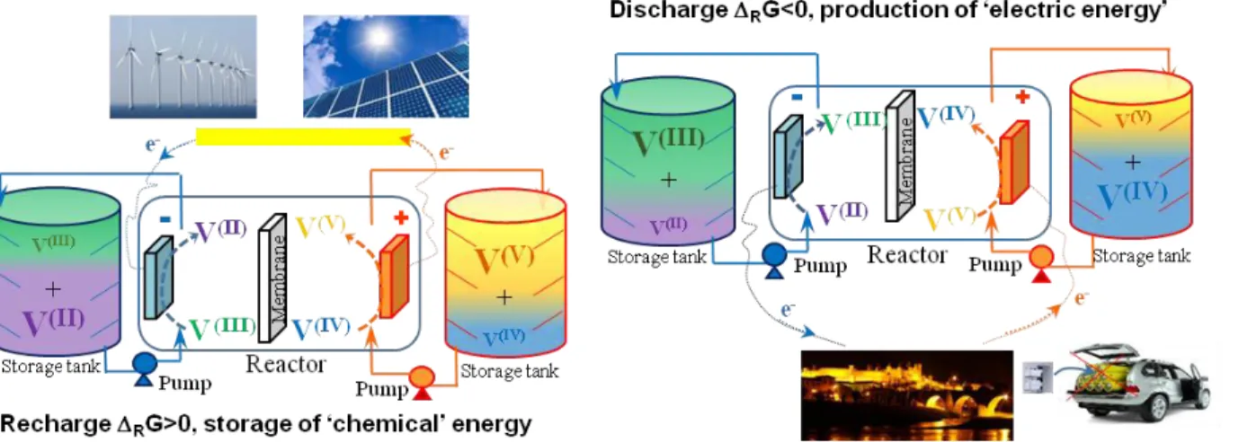
Fig.I.3: Schematic presentation of the all-vanadium redox flow battery during charge and discharge
As presented in the figure, each one of the four oxidation states of vanadium has a characteristic color when dissolved in concentrated sulfuric acid, used as supporting electrolyte: V(II) is violet, V(III) is green, V(IV) is blue and V(V) is yellow. This can be useful for a visual/qualitative interpretation of the state of charge of the battery. During the charge VO2+ is oxidized to VO2+ in
the posolyte and V3+ reduced to V2+ in the negolyte; the opposite reactions take place during the discharge. All the reactions occurring in the battery’s compartments are indicated in table I.3:
Table I.3: Reactions taking place in the battery’s compartments
Simplified Half electronic reactions Complete Half electronic reactions
VO2+ + H2O VO2+ + 2 H+ + e- Rx.I.1 2 VOSO4 + 2 H2O (VO2)2SO4 + H2SO4+2 H++2 e- Rx.I.1’
V3+ + e- V2+ Rx.I.2 V2(SO4)3 + 2e- + 2 H+ 2 VSO4 + H2SO4 Rx.I.2’
Simplified global reaction Complete global reaction
VO2++V3++H2O VO2+ + V2+ + 2 H+ Rx.I.3 V2(SO4)3+2 H2O +2VOSO4 (VO2)2SO4 + 2 H2SO4 +2VSO4
.
![Table I.2: Main applications of vanadium, as classified by the European commission in 2011 [48]](https://thumb-eu.123doks.com/thumbv2/123doknet/2132538.8628/29.918.222.696.243.502/table-i-main-applications-vanadium-classified-european-commission.webp)